Guide to Wire Connection Tester for Assembled Cable Production

CCT-01 is a universal wire connection tester to test all kinds of wiring configuration instantly. Fast cable tester and simple to use.

This device can learn the connection from your original cable wiring, and subsequently test the rest of your reproduced cables.

CCT-01 wire harness tester. A productive tool that you should keep on your tool shelves.

Click here for more information about CCT-01 tester.

Test Setup for D-sub RJ11 Assembled Cable

Imagine you are mass producing a cable (D-sub and RJ11 connectors). You would like to test and ensure the wiring is done correctly before you shipped out to your customer. You can setup the tester as shown in the picture.

D-Sub and RJ11 connector connection tester device (PIC-350)

  1. First step is to buy or prepare the mating connectors for your D-sub connector end, and your RJ11 connector end. The mating connectors are for making the connection to the cables that you wanted to test.
    It acts as an adaptor interface between your cable and the CCT-01 tester.
  2. You can wire up the individual wires to any of the port connectors on CCT-01. It does not matter which port you connect because the device can learn the wiring connection on-the-fly. You just need to ensure all the wiring are connected.
  3. Power up the CCT-01 through a USB mini-B cable.
  4. Connect your original master cable (a sample with the correct wire connection) to the CCT-01 via the adaptor interface that you had prepared in step no. 1.
  5. Press the learn button to allow the device to learn the connection from this master cable.
  6. You can then proceed to swap the master cable with the cable which you want to test
  7. Press the TEST button to begin testing.
    The device will indicate a green light and a valid beep sound if the connectivity is the same.
    A red indicator and an error buzz sound will be sound if the cable does not have the same wiring connection.
  8. Continue to swap to test the remaining batch of your cables.

This tester is designed to be a simple general multi-purpose cable tester. The same test procedure applies to any complex cable harness wiring configuration. Simple to use.

Wiring Connectivity Tester (PIC-350)

online electronic circuit kit Singapore | PIC-store
Click here to buy
.

Check out other references…

Cable Connection Assembly Tester

Cable Connection Assembly Tester

A simple to use cable-tester. One touch button to learn from your master cable, and another button to test your production cables.

Setting Up for Cable Testing

The following is a guideline to using this cable tester to test your cable or wire harness.

  1. Get ready the cable that you want to test.
  2. Prepare the mating connectors for your cable.
  3. Crimp, solder or attach a wire to each pin of the mating connector.
  4. Connect each of the wire to each of the terminal port on the Cable Tester. (You can connect up to 64 points)
  5. Power up the cable tester via the USB mini-B socket.
  6. Connect your Master cable to the mating connectors that are now attached to the Cable Tester.
  7. To learn the wiring of your Master cable, press and hold the small learning touch button on the Cable Tester device. Hold it for about 3 sec until you hear a double beep or see the PASS & FAIL LED flashing.
  8. The Cable Tester device has learned your Master cable.
  9. Remove the master cable from the mating connectors.
  10. Replace it with the production cable that you want to test.
  11. Press on the “Start TEST” to begin testing the cable. The test result will be available almost instantly within a second.
  12. You should be able to see a green LED PASS lighted up if the cable has the same wiring configuration as your Master cable.
  13. If the cable is not the same, you should see a red LED FAIL light up.

Cable Connection Test Report

This cable tester can also be connected via a USB cable to the computer for the display of the cable test result report.

You can use the following software to view the cable tester connectivity report.

Communication baudrate settings: 115200bps, 8 data bits, 1 stop bit, no parity bit, no hardware flow control.

There are a few commands which allow you to measure and generate the cable wiring report.

  • Generate a test report with reference to your master cable.
  • Current cable connection report.
  • Master cable connection report.
  • Learn cable connection and save the wiring configuration as the master template.

Through this report, you are able to see at a glance how a cable is being wired. A master cable wiring configuration can be saved to this tester. This tester can then base on this master cable wiring pattern and test the rest of your production cables.

Cable connection test report

Up to 64 connection points can be tested. A1 to A8 …. to H8 represent the 64 terminal points on this Cable Tester device.

Total EEPROM memory required for 64 connection is 4Kbits (64 x 64 connection points).

Test Result Example:

O – Correct Connection      
M – Missing Connection      
X – Wrong Connection      
– Correct No Connection      
         

Fully Automated Test Solution

This cable tester can also be integrated into your production machine for a fully automated test system for your cables.

Click here to check up more details of this PIC-350 Cable Harness Connectivity Tester.


Payment Terminal

       Cashless Payment Terminal in Malaysia

Payment Terminal Vendors

Online Cashless Payment Vendor

Cashless Payment in Malaysia

  • Touch n GO cashless card payment Touch n GO
  • Alipay QR Code Payment Alipay (QR code)
  • Visa Credit Card Payment Visa
  • MasterCard PaymentMasterCard
  • American Express Payment American Express
  • UnionPay Payment UnionPay
  • JCB Payment (Japan) JCB
  • MyDebit Card Payment MyDebit

Automated Vending Machine Integratation

Contact our sales engineer from PIC-CONTROL for your automated payment terminal integration.

Coin Notes Acceptor and Dispenser Machines Singapore

This page contain references to buying of a coin dispensing machine and notes-to-coin machine. Coins, Notes and token solution for your automated business payment collection.

Bills and Coins Machine Product Companies

Bills to Coins Changer

Notes to Coin changer machine

Bills Validater / Note Acceptor

Money Notes Acceptor device

Coin Accepter

Coin Acceptor device

Coin Dispenser (Hopper)

Coin Dispenser device

Custom Cash (notes & coin) system.

We can help you to design a system suitable for your application use.

For customised automatic cash (notes and coins) payment collection system, please contact our sale engineer with your project details for a quotation.

Cashless Payment Terminal

Customised HAT | Attachment Board for Raspberry Pi

Raspberry Pi HAT (Hardware Attached on Top) is a specification that allows developers to create add-on boards that extend the functionality of Raspberry Pi computers. Customised modules for Raspberry Pi HATs are designed to meet specific needs or applications, offering tailored features and capabilities that standard modules may not provide. This flexibility is one of the key advantages of the Raspberry Pi ecosystem, enabling hobbyists, educators, and professionals to innovate and create unique projects.

Customised Module for Raspberry Pi

We can help you customise an attachment suitable for your application.
Ensure that your device can be as compact as possible.
Neater and more reliable wiring connection.

More customise features

  • Power up your Raspberry Pi from a wider input voltage range from 12Vdc to 24Vdc.
  • Communication features RS232, RS485, Zigbee, Wifi, etc…
  • Digital I/O (input/output).
  • Analog signal sensing inputs.
  • Sensors interface.
  • NFC or RFID attachment.
  • LED lighting effect control.
  • Motor driver and control.
  • GPS geographic location sensing.
  • User Graphic Display.

Contact PIC-CONTROL in Singapore for more information.

Other Raspberry Pi Form Factors and Models

Raspberry Pi Model BRaspberry Pi Model ARaspberry Pi Zero

  • Raspberry Pi 3 Model B+
  • Raspberry Pi 3 Model B
  • Raspberry Pi 2 Model B
  • Raspberry Pi 1 Model B+
  • Raspberry Pi 1 Model A+
  • Raspberry Pi 1 Zero W (with wireless and Bluetooth)
  • Raspberry Pi 1 Zero
  • Compute Module 3, Module 3 Lite, Module 1
  • Compute Module IO Board V3

Raspberry Pi Compute ModuleRaspberry Pi Compute Model I/O Board


References

Cashless Payment System Singapore


Looking for a cashless payment system for your automated machines?

PIC-CONTROL provides solution to allow your machines to accept cashless payment in Singapore.
We have a simple package plan to help you automate your machine to collect payment 24 hours a day, 7 days a week.

Advantages of a Cashless Payment System

More and more customers are using a cashless card to make payment for their purchase. Customer may not have enough cash notes/coin but they definitely have a cashless card for their daily shopping or transportation in Singapore.

  1. Increase Sales
  2. Fast and Convenient
  3. No more collection and handling of cash money notes/coins
  4. Reduce the administration, operation, maintenance and banking cost.
  5. Daily transaction report
  6. Able to accept a variety of payment amount (unlike a notes or coin acceptor).
  7. More robust (no mechanical part)
  8. Customer does not need to look for cash notes/coins for the purchase.
  9. Machine does not need to return change or hold cash.
  10. Contactless payment. (Hygiene from germs, bacterial compared to notes/coins)

The use of a cashless payment system eliminate the need of handling of coins. Coins handling charges by the bank can be very costly.

Application

More and more customers are carrying less cash (coins and notes) in their wallet. Cashless is more convenient and faster transaction. Improve and automate your sales by using a cashless payment system.

Cashless Payment for soft drinks dispenser mahine     Cashless Payment for snacks vending machines     Cashless Payment for Toy Catcher machine

Cashless Payment for Drink dispenser machine     Cashless Payment for Coffee Machine     Cashless payment for Kiddy Ride machine

Cashless Payment System for Machines

We offer Rental Package

For $5-$8 dollars a day (yearly package), you will get to own your cashless payment system
to increase your sales and improve your operational efficiency.

Monthly/Weekly rental is also available. Please contact us for the package rates.

Why Rental?

Focus on your business and leave your engineering headache to us.

We have design this package to help businesses cap the cost of maintaining a cashless payment system, as well as lowering the initial engineering cost. Simple to understand price ceiling so that you will not have any price shock.

Technical engineering care support is inclusive in this rental package to ensure that any of your technical problem will be resolved. Free consultation on your machine even if it is not relating to the payment system. This is our support to ensure that your machine will operates smoothly. You success is our success.

Cashless Payment System Singapore

Package Monthly Rental Rate (2 years contract, billed yearly)
[1] Wired internet connectivity available onsite. S$170 per month
[2] No internet connectivity available onsite. or Wireless connectivity. S$230 per month

** Rental package is INCLUSIVE of integration work. Subjected to our sales engineer’s assessment.

** Typical lead time for the engineering integration work takes about 6-8 weeks time.

** Standard vending payment procedures. (MDB Payment Terminal model)

** Price package is subjected to our project feasibility assessment.

Charges

We would like to make the pricing clear and simple to understand for our clients.

  • 1 year advance rental payment. (assuming Package [1], this will be S$1800)
  • 3 months rental deposit. (assuming Package [1], this will be S$450)

The total down payment for Package [1] is $2250 + GST.
Subsequent rental payment will be collected yearly in advance.

Other charges

  • Per transaction charges (typically 0.8%, 1.6% to 3%-5%). Depending on your selected payment service provider. Ezlink, Nets and Banks for (Visa, MasterCard)
  • Opening of account is required for each type of card payment that you want to accept. There is no charges to the opening of the accounts from us. Some banks or service provider may charge a small fee for using their facilities. You can source or negotiate for a better rate.

Not inclusive of

Every project is unique on its own. If your project requires additional complex work there may be additional engineering cost involve. We can waive off simple engineering work. Please contact us for an assessment. The additional cost would probably comes from the following scenario.

  • Electrical and cabling work.
  • Complex custom enclosure work.
  • Complex integration work.
  • Non-standard vending payment procedure. (Customised payment process, or non-MDB payment process.)
    Click here to read more about the standard MDB payment process here.
  • Additional note collecting peripheral (+$50/month)
  • Additional coin collecting peripheral (+$10/month)

Site infrastructure that you should provision for your project

The following are some of the infrastructure you can start to provision for your cashless payment system.

  1. 1x or 2x Power Point Socket
  2. 1x Ethernet socket (with connectivity to the internet)
  3. Connectivity to machines (May not be applicable to your project)

For your reference, you can check out the dimension size of the payment reader terminal for your machine.

For remote mobile data connection option, check out the standard size dimension of the 3G/4G router modem.

Cashless Payment Mode

There are various card and mobile phone payment available to choose from. Additional charges applies for each transaction. Some providers or banks may charge for opening an account with them. The account offered may change from time to time. So it is good to compare the package offered and negotiate with them for the best rate. We will guide you along for your account opening when you take up our rental package.

The following are the payment mode available to choose from,

  • Ez-Link (CEPAS)
  • Net FlashPay (CEPAS)
  • Visa PayWave
  • MasterCard PayPass
  • AMEX
  • PayNow PayNow logo
  • SGQR
  • Alipay Alipay logo
  • WeChat pay Wechat pay logo
  • Apple Pay
  • Google Pay
  • JCB, Diners, UPI (NEW)
  • GrabPay & Singtel Dash (NEW)

Custom Cashless Payment Integration

Send in your enquiry to PIC-CONTROL today for your customised cashless payment system.

Send in the following information,

  1. Photos of your machinery.
  2. Machine Documentation (User Manual, Technical Manual, etc…)

Reference:

Microcontroller Firmware Programming Upload with MPLAB X IDE

Introduction

This section provides fresh user a step-by-step instruction to upload your updated firmware (a program or machine codes) onto your circuit board using a Microchip microcontroller.

Microchip logo

Things That You Need To Prepare

  1. Your Microchip microcontroller circuit board
  2. Programmer Tool (PICkit)
  3. MPLAB X IDE (Integrated Development Environment)
  4. Firmware (a hex code file *.hex or project files, containing the program of your controller)

Once you are prepared, you can proceed step-by-step to upload your firmware to your microcontroller.

Microchip Circuit Board

Most microchip circuit board design by PIC-CONTROL comes with a programming port which allows us to upload the program onto the microcontroller chip onboard.

There are standard microchip programming port also known as ICSP, which you can connect to with your programmer tool.

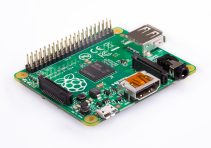
Programming Connector Port on your circuit board product

The programming port is usually located near the edge of your circuit board. It is a row of 6 holes grouped up with a rectangular box (2.54mm pitch header pins).

You must know how to identify the pin no.1 on this port. Pin number 1 of the footprint is indicated by a triangle arrow marking. You can also identify this pin 1 from the bevel corner on the rectangular box.

The following are some photos of how the ICSP programming port looks like on your circuit board.

ICSP programming port on PCB board     ICSP programming port on PCB board     ICSP programming port on PCB board

smd ICSP programming port on PCB board (without holes) 
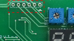
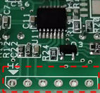
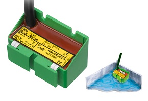
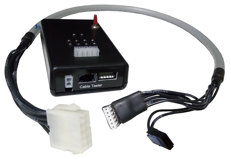
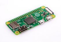
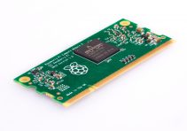
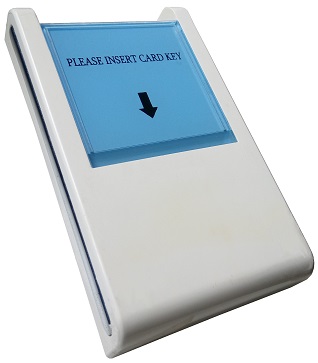
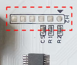
ICSP (a special version without any holes)

You are suppose to connect the programmer tool to these ICSP port, with alignment to the pin 1.

Details of the procedure will be provided in the later section below.

Programmer Tool

You will need to get yourself a programmer tool. A programmer tools helps you to connect your computer to your microcontroller chip. It is used for uploading of the microcontroller firmware (controller program) onto the microcontroller on your circuit board.

There are a number of programmer tools which allows you to upload your firmware. In this example, we are using the official PICkit 3 or PICkit 4 programming tool from Microchip.

Other commonly known programming tools available are ICD4 (In-Circuit Debugger), ICD3, PM3 and REAL ICE.

Please take note of the pin no.1  on the programmer tool. You must identify this pin and align it to the pin 1 of the ICSP port on your circuit board.

PICkit 3 Programming Tool

PICkit 3 programmer tool

PICkit 3


PICkit 4 programmer tool

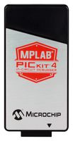
PICkit 4 (new version)

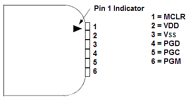
PICkit Programming Tool’s Pin-out

This is the PICkit programmer pin-out. This pin-out is also known as the ICSP programming port.

Please take note that the pin no.1 is identified by the triangular arrow head.

PICkit 3 programmer pin out

MPLAB X IDE (Integrated Development Environment for Microchip Microcontroller)

The last item that you need is the software which allows you to develop and upload your program to your microcontroller chip.

MPLAB X IDE is a free microchip microcontroller development software. It is a complete platform for your firmware coding development work.

What you should do now is to download the following,

  1. MPLAB X IDE software (Windows version).
  2. MPLAB XC Compiler.

Download & Install the MPLAB X IDE Software MPLAB X IDE

You can click on this shortcut link to download the latest MPLAB X IDE software (Windows version). If this links cannot work, please follow the steps here to download from the Microchip official website.
https://www.microchip.com/mplab/mplab-x-ide

  1. Click here to go to the Microchip website for MPLAB X IDE software.
  2. Scroll down to the bottom of the page and look for the “Downloads” tab to click on.
  3. Go to the respective version (Windows, Linux or Mac) and download the software.
  4. As of this point in time the software is of version “MPLAB® X IDE v5.05

Install this software to your computer.

Download & Install the MPLAB X Compiler MPLAB XC Compiler

The compiler converts the programming source code into a machine code before you can upload the program into a microcontroller chip. Different microcontroller would requires its respective compiler. It is recommended to install all the compiler as follows.
http://www.microchip.com/mplab/compilers

Install these MPLAB XC8 and MPLAB XC16 compilers to your computer.

Step-by-Step Procedure to Upload Firmware to Microcontroller Chip

Now that you have your

  • Circuit Board
  • Programmer Tool
  • MPLAB X

ready…

We can start to upload your project or *.hex file..


There are two modes of uploading firmware to the microcontroller.

  1. Method 1: Upload hex.* file (machine code) using MPLAB X IPE software.
  2. Method 2: Upload project (source code) using MPLAB X IDE software.

Method 1: Firmware upload using IPE Software

This method is usually used for the production. Programmer operators will be provided with a *.hex file for them to upload the firmware to the microcontroller chip.

The advantage of this method is that it is simple, and it do not expose your actual project source code.


Step 1: Launch the program MPLAB X IPE software.

IPE software launch up screen shot

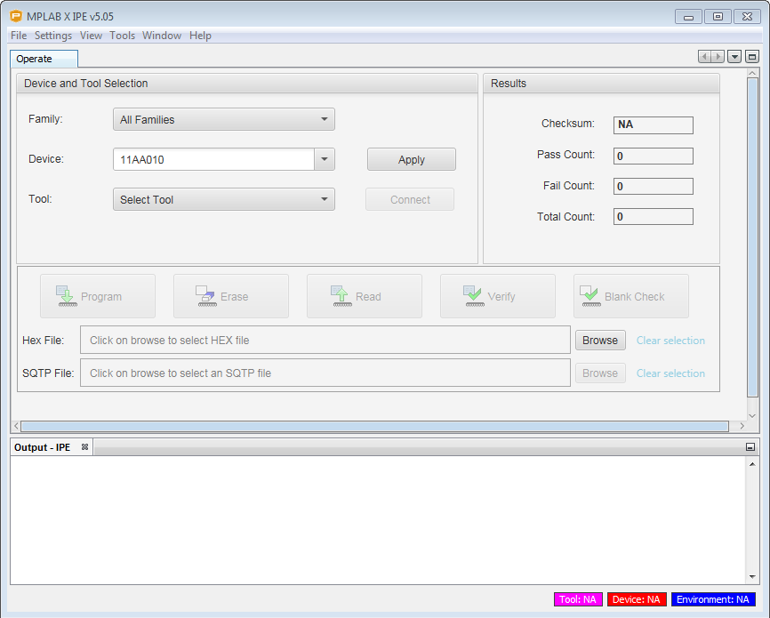
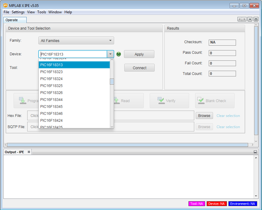
Step 2: Under the section “Device:“, select the microcontroller part number that you want to load your firmware to. Refer to your schematic for the exact microcontroller part number.

Click on the button “Apply“.

IPE selecting microcontroller device

Step 3: Plug in your programmer tool to your computer.

You should notice that the software update the “Tool:” section once your tool is detected.

IPE programmer tool detected

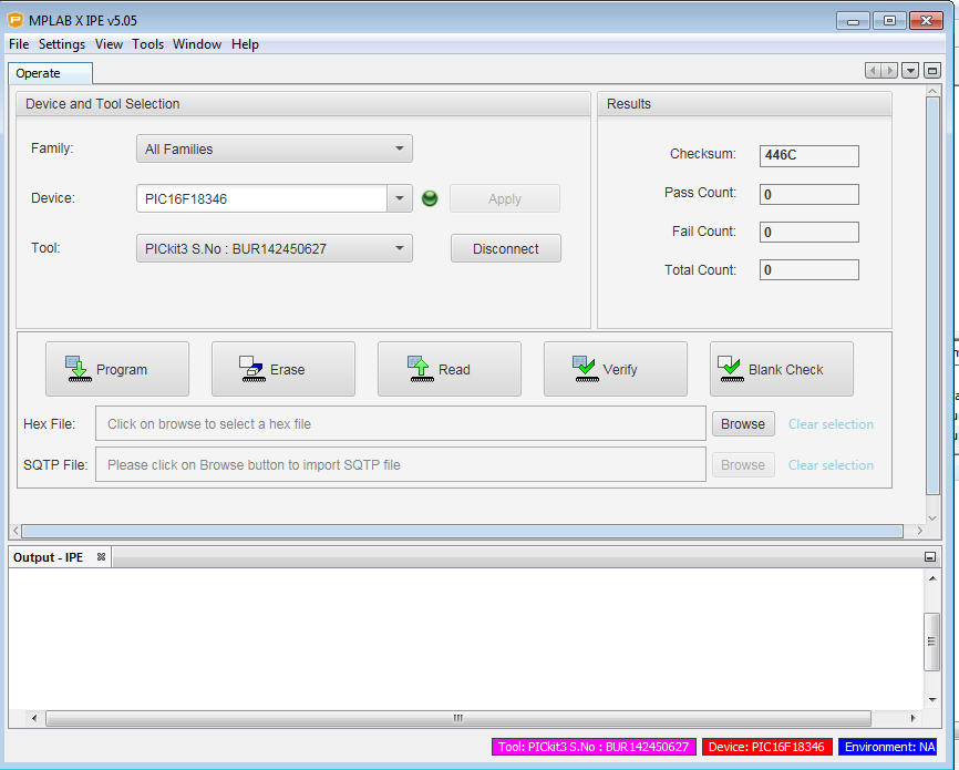
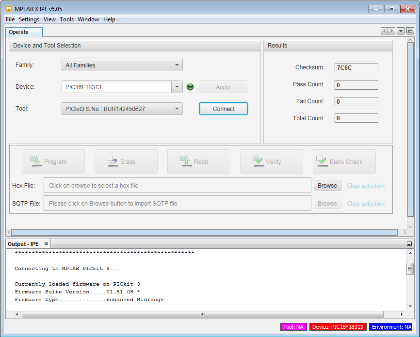
Click on the button “Connect” to start connecting to your programmer.

You should see the following message printed out…

*****************************************************

Connecting to MPLAB PICkit 3…

Currently loaded firmware on PICkit 3
Firmware Suite Version…..01.51.08 *
Firmware type…………..Enhanced Midrange

IPE programmer tool successfully connected

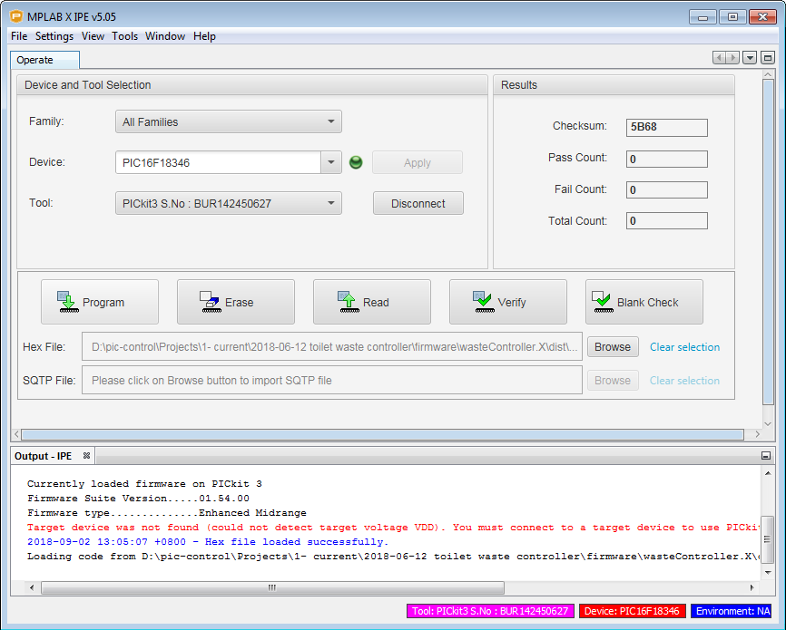
Step 4: Under the section “Hex File:“, load your *.hex file for your production. This is the machine code file for your circuit board. This is the only file required for the production.

For a start, this file is located in your project folder. For example…
Your project directory -> “yourProject.X\dist\default\production\yourProject.X.production.hex

Step 5: Connect your programmer tool to the ICSP port on your circuit board. Make sure that the pin 1 on your connector is aligned correctly. Then power up your board.

Step 6: Click on the button “Program” to start the uploading of your firmware to the microcontroller chip on your circuit board.

IPE program button

Yes, you are done. Congratulation.
Your board is successfully loaded with the firmware.

Method 2: Project source code upload using IDE Software

This method is usually used during the development. Engineer can edit the source code and upload the firmware changes onto the microcontroller chip directly.

It is recommended to maintain your firmware version while you are doing editing and improvement work. Keeping the original functioning version is a must. You can always fall back on the original copy if you mess up the project source codes.

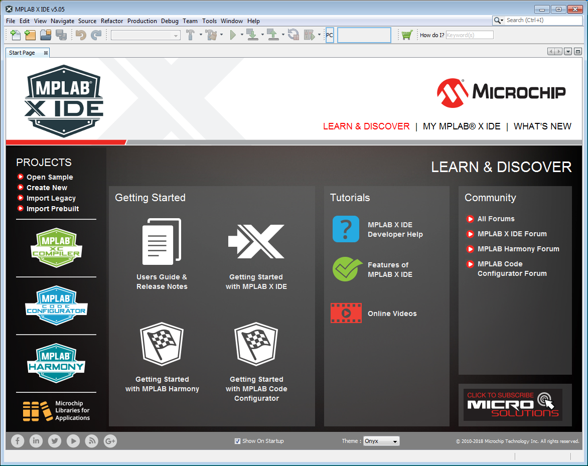
Step 1: Launch the program MPLAB X IDE software.

MPLAB X startup screen

Step 2: Open up your project files. Go to File > Open Project…

Select your project files. It is the project folder which ends with *.X. For example “yourProject.X”

MPLAB X select project file

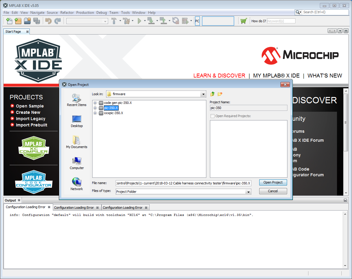
The project will loads up.

MPLAB X upload firmware to microcontroller IC chip

Step 3: Plug in your programmer tool to your computer.

Step 4: Connect your programmer tool to the ICSP port on your circuit board.
Make sure that the pin 1 on your connector is aligned correctly. Then power up your board.

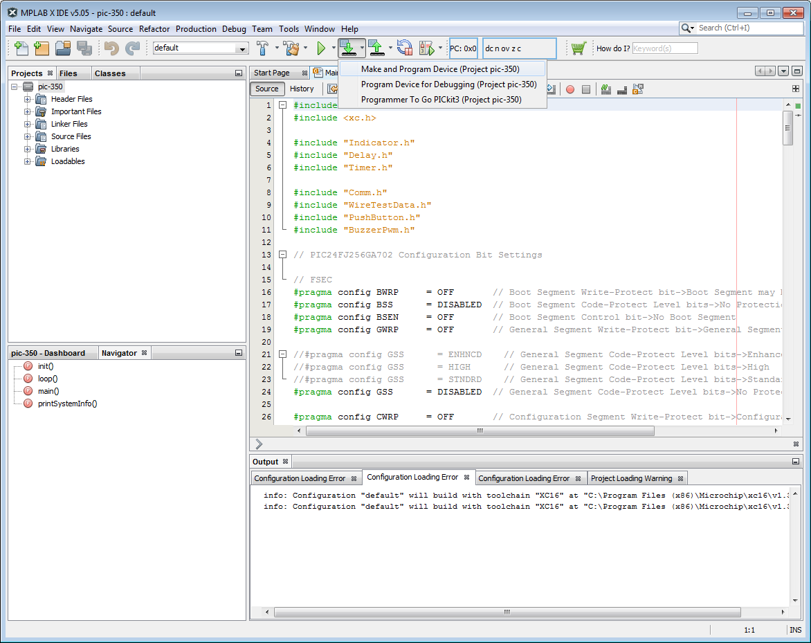
Step 5: Click on the arrow down icon below the menu bar.
Select “Make and Program Device” to start the uploading of your firmware to the microcontroller chip on your circuit board.

Yes, you are done. Congratulation.
Your board is successfully loaded with the firmware.

More…

For further details, you can check up the Microchip official website Microchip logo
or YouTube YouTube logofor a more detailed instructions.

Hotel Card Key Switch

Contactless Card Key Switch for
Hotel, Dormitory or Rental Room

This card key switch is designed to be activated by a contactless card. Only a contactless card can activate this switch for powering up the electrical system in a room. A normal card cannot trigger this card key

contactless hotel card key holder

Blue Glow Indicating Card Key Holder

Card key holder will glow softly in the dark to guide the guest to slot in their contactless card key.

The relay switch gets activated to turn on external power control system. The power system will switch on the electrical system in the room.


blue glowing hotel card key switch

Key Card Switch operated by RFID electronic circuit

Custom RFID reader circuit for hotel card key

RFID Switch BMS-RFS001-V1 circuit board for hotel card key
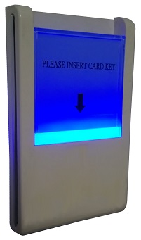
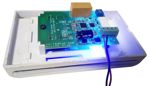
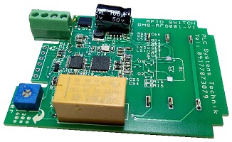
RFID Switch BMS-RF001-V1


RFID Switch product by PLC Systems Technik, Philippines

Note: Please take note that this is only the key card holder to detect the contactless card. It cannot be used to power up your electrical appliance. External power control system is required to power up the rest of the electrical appliances within the room. The following examples of high current appliances have to be powered up by an external interface.

  • Aircon
  • Lightings in the room
  • Heater
  • Fridge
  • TV
  • etc…

Other Custom RFID Products


Water Leakage Sensor

This page explores the various type of water sensor for the detecting of water leakage. These sensors are commonly used to detect or monitoring of water leakage from aircon condensation.

Aircon condensation water leakage is a very common sight in the industry. This problem is normally due to improper design and installation of the water drainage pipes. Water drainage pipes installed were too small resulting in water clogged by dust or mould when used over time. Some water drainage pipe was seen to be installed in a anti-gravity manner, which makes it impossible for any water to drain out.

->> Click here to learn more other problem relating to aircon water leakage.

It is important to ensure how these pipes are deployed during the installation process so that you will not be faced with water leakage issues.

If you are already facing the problem, consider reconstructing your water drainage system or implement the following sensor to reduce your trouble.

Aqua Switch Water Sensor

AquaBlock or Aqua switch is installed in water tray for detecting of water leak from aircon or pipes. It can also be mounted at a specific height in the tank to detect water level. The aqua switch is only a block and does not have any moving parts.

Click here to buy Aqua Switch water leakage detector sensor online.

S$285+GST

Aqua Switch

Aqua Block

The sensor is a simple relay switch which will activate when water touches the sensor block. It can also be used as a water level detector when mounted at a certain height.

Advantages

  • No moving mechanical parts
  • Relay output (dry contact switch output)
  • Simple to install
  • Suitable for aircon water leaking detection

Click here for more detailed information of this Aquaswitch water detector sensor.

Or you can also click here to buy Aqua switch sensor.

Water Leak Sensor Cable

This sensor looks like a yellow cable or rope. This sensor cable is typically laid on the floor or above the ceiling to detect water leakage. Any water touching this water sensor can be detected by the connected electronic sensor box. The cable can be place where water leakage is likely to be found.

This type of sensor cable is commonly deployed in computer server room where there are many aircon system installed. Aircon leak is a common problem in a server room.

Other Type of Water Sensors

Check out our other pages for more water sensing technology.

Contact PIC-CONTROL for further information.

Cable Harness Tester Equipment

Tester for your cables harness production

Affordable Cable Tester

Click here to check for a simple comparison table of cable tester equipment.


CCT-01 Cable Harness Connection Tester

CCT-01 Cable Harness Connection Testerwww.Cable-Tester.com logo

Very affordable and productive connectivity test for your assembled wired.

  • Ability to learn from a good cable connection sample in a few seconds.
  • Test your production cable in a second.
  • Pass/Fail test feedback with Buzzer sound & LED indicators.
  • 64 test connections (cascade to expand for more test connections)
  • Portable size and light in weight.
  • USB 5V powered (can be powered up by power bank too).
  • Stand-alone tester.
  • Connection report display available via the USB port.
  • Tester for any types of cable’s connector.
  • Interface available to trigger external equipment/devices.
  • Safe, Simple and Easy to use.
  • At a very affordable cost.
  • Operating Power: USB 5V
  • Size:  130mm x 65mm x 35mm
  • Weight: 400g

Also available from PIC-CONTROL. Click here.

KT210 Cable Tester (Low Cost)

CTS KT210 Cable TesterCTS Combined Test Solutions logo

  • Stand-alone (no need a computer attached)
  • Self-learning of a good cable connection.
  • Test result report
  • Different languages to choose from
  • Test up to 512, expandable up to 2048 connection points.
  • Low voltage test 12Vdc 10mA
  • Continuity test, short circuit test and component testing.
  • Microsoft® network interface
  • USB 2.0 interfaces
  • 2 GB storage for test programs and results data (expandable)
  • Remote maintenance via network.
  • Interfaces to control external apparatus such as cutter, marker etc.

1000RX Cable Tester (Low Cost)

CTS 1000RX Cable TesterCirris Systems logo

  • Fast and easy testing
  • 128 test points expandable to 256 points.
  • Detects open, short circuit, or miswiring with resistance as low as 0.1 ohms.
  • Design for high volume testing.
  • Display for the operator (2 lines x 16 characters)
  • Step-by-step assembly instructions.
  • Allows connection to a computer for admin configuration and test data report.
  • Wire identification probe.
  • Test at 5.5Vdc
  • Resistance threshold from 0.1ohm to 5Mohm.
  • Test report print out.
  • Power required: 115Vac/230Vac
  • Size:  270mm x 170mm x 50mm
  • Weight: 1900g

uTestem

uTestem Electrical Analyzer for cable harnessEMDEP logo

  • Hardware self test
  • Connector lock test
  • Detection test
  • Open circuit test
  • Short circuit test
  • Resistance threshold setting
  • 128 test points expandable to 256 points.
  • Display for the operator (4 lines x 40 characters)
  • Buzzer
  • Interface to external equipment/devices
  • Power required: 115Vac/230Vac
  • Size:  300mm x 100mm x 125mm
  • Weight: 2500g

PAL1570 PC Cable-Check Cable Tester

Cable Depot PAL1570 PC cable testercable depot logo

  • Suitable for cable/connectors normally used on a computer PC.
  • Identify open, short, and wrong wiring connection
  • RJ45, RJ11, RJ12, RG58/59 BNC
  • DB09, DB15 DB25 male/female connectors
  • DH15 (VGA) male/female connectors
  • USB type A, B and mini plug
  • 1394 Firewire
  • MD04 (SVHS / MD06 (PS/2 Keyboard or Mouse) jacks
  • CN36 female connector
  • Operates from 9V battery
  • Size:  280mm x 169mm x 46mm
  • Weight: 7700g

PC Cable Tester

PC Cable TesterHobbes Innovation logo

Model No.: 258991A (USB, 1394, SATA)

  • Tester for commonly used cables on a computer.
  • Test cable connectivity, open/short/crossed/mis-wiring/continuity.
  • Test for cross cable.
  • Connectors: TX: DB25 M/F, DB9 M/F, HDB 15/M, RJ-45/F, RX: Centronics 36/F, DB25 M/F, DB9 M/F, HD15/F, DB15F, RJ-45/F
  • Operates from 9V battery or 9Vdc power jack
  • Size:  250mm x 130mm x 35mm
  • Weight: 400g

Multi Function Cable Tester Pro

Multi Function Cable Tester ProLindy Connection Perfection

  • Portable
  • Quick and Easy to use
  • Check for open/short/cross/mis-wiring and continuity problem.
  • Support 18 types of cables
  • USB connection for up to 100 test results.
  • Driver software available for download.
  • Screen display.
  • Connectors: IDC40, IDC34, DVI29, HDB15M/F, DB9M/F, COAX, BNC, RJ11, RJ45, 1394-6P, 1394-4P, SATA, USB(A/B), HDMI, RCA
  • Operates from 9Vdc power


CT-16 Cable Tester

CT-16 Cable Tester   CT-16 Cable Tester (IDC connection adaptor)

WireBasics logo

Perfect for testing cables of all kinds and wire harness assemblies.

  • Programmable logic to detect open short and cross connection.
  • IDC connectors (suitable for general cable testing)
  • IDC adaptors kits add-on for your own cable’s connector type.
  • Pass/Fail indicators
  • Interface to external devices
  • Portable compact and light weight.
  • Operates from 9V battery


CCT-02 Universe Cable Tester

CCT-02 Universal Cable Testerwww.Cable-Tester.com logo

High test points capacity Universal Cable Tester.

  • Ability to learn from a good cable connection sample in a few seconds.
  • Test your production cable in a second.
  • Pass/Fail test feedback with Buzzer sound & LED indicators.
  • 256 test connections
  • Portable size.
  • USB 5V powered (can be powered up by power bank too).
  • Stand-alone tester.
  • Connection report display available via the USB port.
  • Tester for any types of cable’s connector.
  • Interface available to trigger external equipment/devices.
  • Safe, Simple and Easy to use.
  • Operating Power: USB 5V
  • Size:  220mm x 165mm x 50mm
  • Weight: 1000g


High-End Cable Tester

8740N Cable Harness Tester

Microtest 8740N Cable Harness TesterMicrotest logo


Cable Eye M2U Full Cable Tester

CAMI CableEye Full Cable TesterCAMI Research logo


UT8080 Series

UT8080 Cable Harness PCB FPC TesterUTRON logo


Benair B857 Connection Tester

Benair B857 Connection Tester


NX Hipot Test System

Hipot Tester for cablesDynalab logo

SanShine


High Voltage Cable Tester

CableEye HVX

CAMI CableEye High Voltage TesterCAMI Research logo

SEFELEC


Cable Tester Equipment Comparison

Cable Tester Catagory Affordable         High-end
 

Low cost cable connection tester
PIC-350
or
CCT-01

CT-16 Cable Tester
CT-16

PC Cable Tester
258991A
Multi Function Cable Tester Pro
Lindy
CTS KT210 Cable Tester
KT210
Microtest 8740N Cable Harness Tester
Hipot Tester for cables
Features            
Cheap (price as of May-2019) √√
≈USD210

USD395
√√√
≈USD120-150

≈USD430
X
Easy to operate √√√   X
Easy to setup √√   X
Low power USB (5V) 9V batt 9V batt 9V power   X
Portable (small in size) √√   X
Fast testing  
Test more than 100 connections need to cascade X X    
Can generate Test Report        
Insulation Test (high voltage) X X X X  
Conductivity Test (high current) X X X X  
Interface to external devices        
Suitable for any cable/connectors X  


Customised Your Own Cable Tester

Customised design and made cable tester for your production testingProduct wiring connection tester

PIC-CONTROL can help you design and custom made a cable tester for your production needs.

A dedicated test can be designed onto the tester.

  • Basic connectivity check for the connection to the correct pin on the connectors.
  • Ohm test or resistivity test for your wires and connectors.
  • High voltage test, to ensure the wires are properly insulated.
  • High-speed data or RF test to ensure signal integrity quality of your assembled cable.


Other Relevant Products

Wire Connector Checker