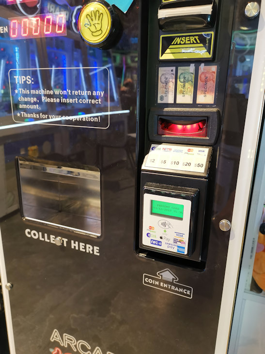
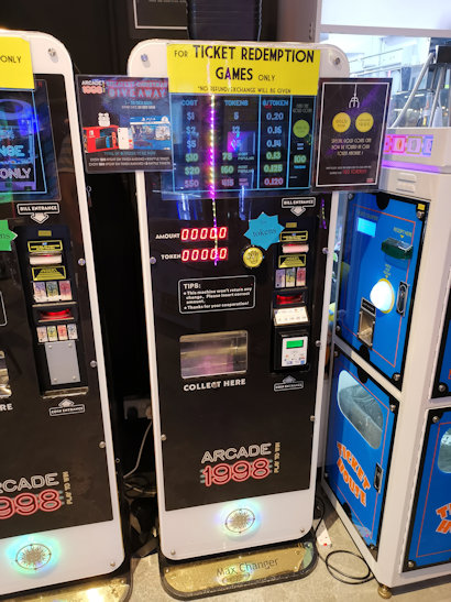
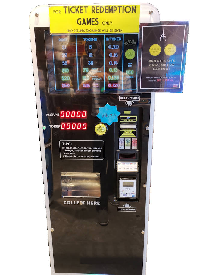
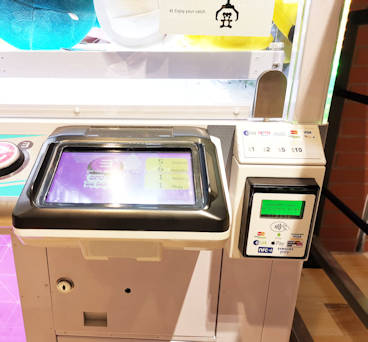
Token exchange machine, of Arcade 1998. Easy to redeem toys. As low as 12 cents per token. Click here to check out Arcade 1998 across the Singapore island.
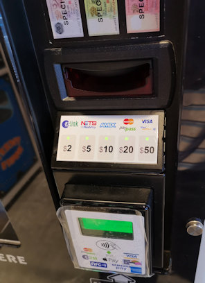
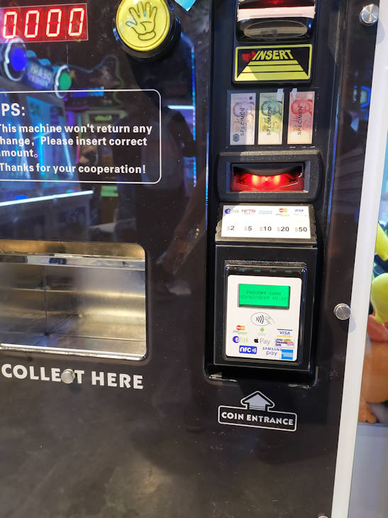
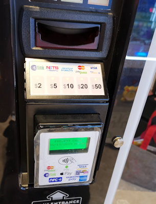
Contact-less card payment system for game token machine in Singapore.
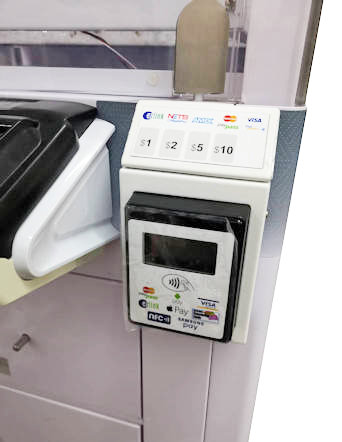
Besides using dollar notes to exchange for coin tokens, your customer can now pay by contactless credit card.
Accepted mode of payment:
Visa PayWave
Master Card PayPass
Ezlink
NetsFlashPay
AMEX
Apple Pay
Google Pay
Other new payment options are available….
Application for Payment System
Game token dispenser vending machine.
Parking ticket/token machine.
Token chip automatic machine.
Automatic coin changer machine.
Movie, concert ticketing vending machine.
Food voucher ticketing dispenser.
Self-service hair cut ticketing payment kiosks.
Custom payment select options of $1 $2 $5 $10 $50.
Custom Payment Design
Contact us for your custom hardware design of your payment system for your machine. Custom process design, enclosure, and user interface.
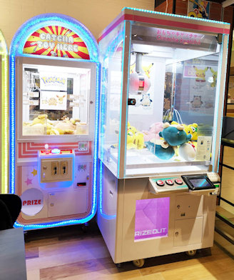
Soft toy catcher machines from Catcha Toy Here. (Original licensed soft toy for catch)
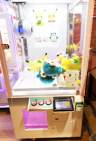
Electronic payment system for toy catcher machine.
Allows customer to pay by credit card, Visa, Master card, AMEX, Ezlink, NetsFlashPay. You can also accept mobile payment through Apple Pay and Google Pay.
Alternate Machine Name
Soft Toy Catcher Machine
Claw Crane Machine
UFO Toy Catcher
Candy Catcher
Application
Other payment system solutions
Contact us for custom payment system design and deployment.
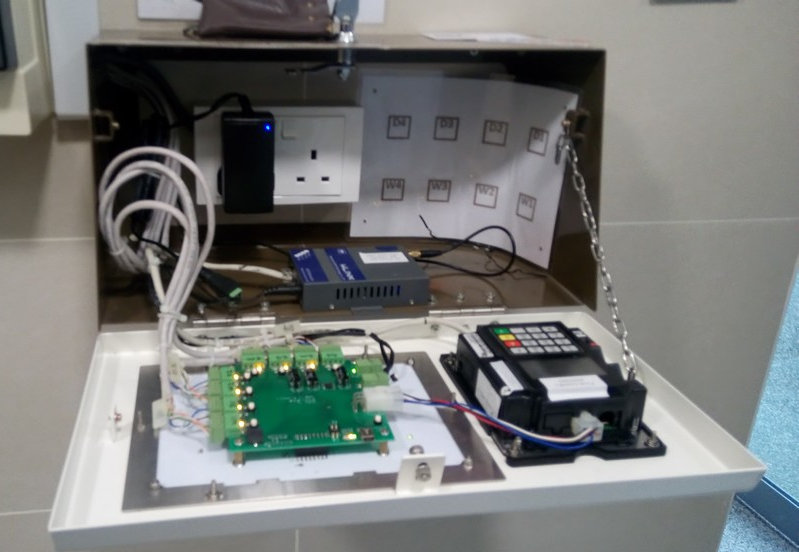
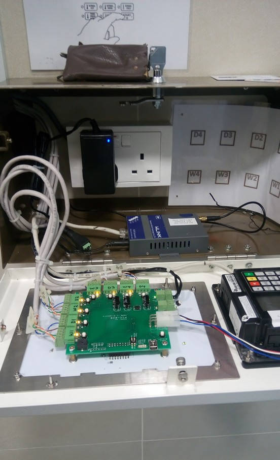
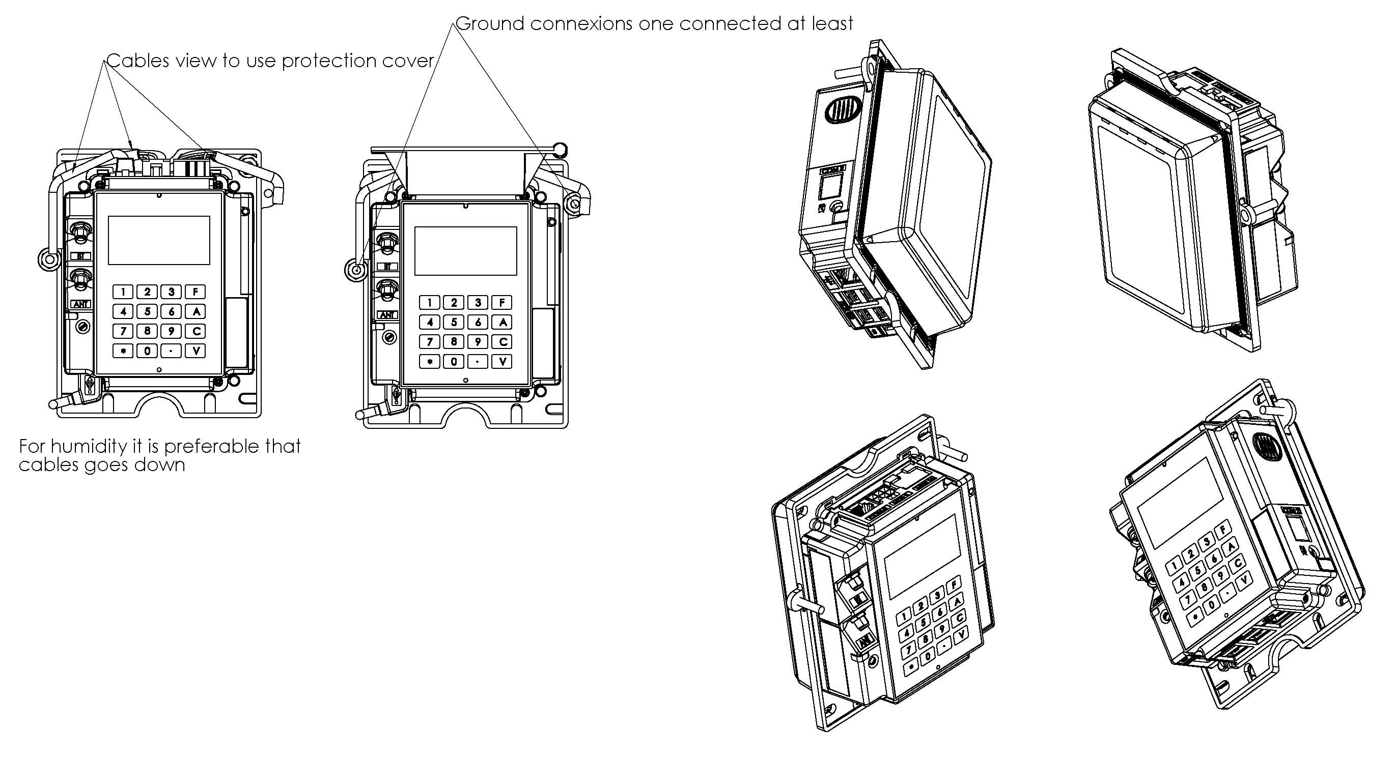
This is an illustration of an installation done. There is no network point in this illustration as it is using a 3G modem for communication instead. The cables are pulled into the enclosure via the cable entry hole channel on the left side of the enclosure.
In a typical setup, the following 3 type of cables has to be laid.
Dual ganged power socket.
Network point socket.
Cables from machines to this payment terminal enclosure.
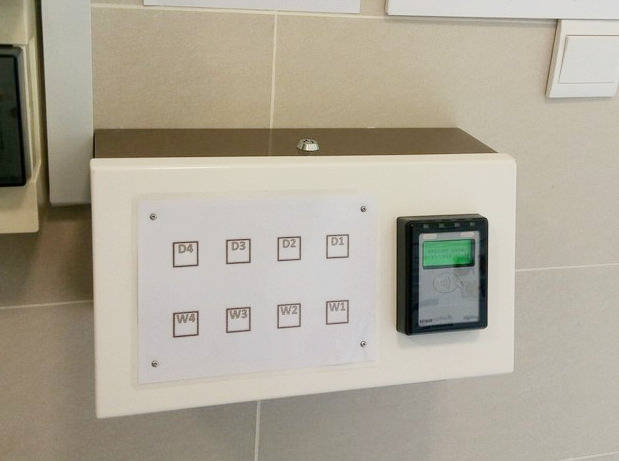
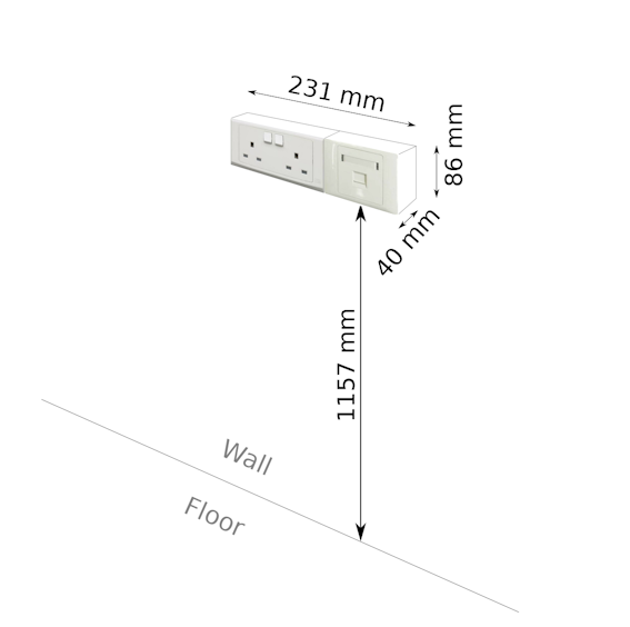
Enclosure Installation Height
The recommended installation height of the power/network socket point is about 1157mm. The enclosure will be installed after power/network sockets are installed. The enclosure will cover directly over the sockets and cable trunking.
The position of the sockets will be the center location of the enclosure. The installed position of the sockets will determine the position of of the payment terminal.
Install the sockets/enclosure at a comfortable and ergonomic high for your user.
The following information provides the internal layout of the casing.
Power Point & Network Point Installation
The payment system requires a minimum of 1x power point and 1x network point. A spare power point is recommended for future use.
Resources to Provision:
2x Power Point
1x Network Point
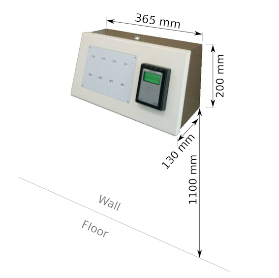
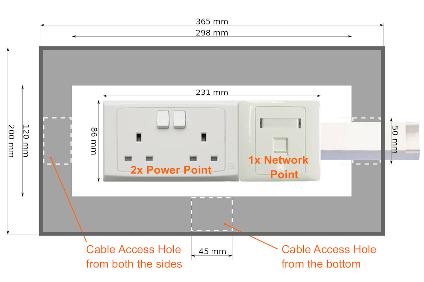
The following is the dimension of the enclosure covering the power point and network point. The opening from the enclosure is about 298 x 120mm. Space is tight. Please ensure that there is enough space for the enclosure to cover over the power/network points on the wall.
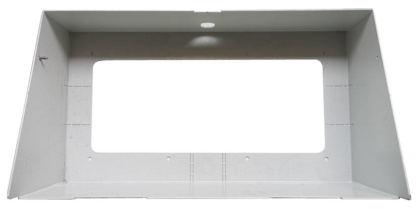
Internal layout dimension of the payment terminal enclosure.Internal structure of the enclosure.
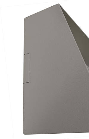
Left cable entry by the side of the enclosure.
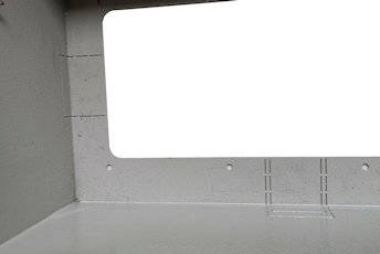
Left and bottom entry for cable trunking.
Please note that there are 3 pre-designed hole channel for cable entry. Two are located by the sides and one at the bottom of the enclosure. The hole channels are aligned to the ceter of the enclosure. It is recommended not to have the cable entry coming from the top of the enclosure, nor the trucking be laid across the top of the enclosure. This is for aesthetically pleasing reason. It will look nicer to select the cable entry channel location to a position that is not too visible. The best entry location will be from the bottom of the enclosure.
The standard width of the hole channel (max) is indicated on the layout above. The holes are design base on the commonly available cable trunking found on the market. Suitable for small and big cable trunking.
There may be situation where the 3 standard hole channel on the casing may not be big enough for the trunking deployed. If the trunking size is bigger than the standard hole channel on the casing, the hole channel will have to be manually enlarge to cater for the massive chunk of wiring.
Cables from Washer/Dryer machines to Payment Terminal
Cables are required from the machines to the payment terminal location. This is to allow the payment system to trigger the machine after the user successfully made their payment.
Cable range AWG20-25 (multi-strand) is recommended. CAT5 cables is easily available and is also fine to use.
Estimate about 1 cable per Washer/Dryer stack. It is recommended to lay a spare cable for every 2 stacks of machine. There are a lot of vibration from the machine, and it is possible that wire may break after long use. This is especially for Cat5 cables as they are only of a single strand. Therefore spare cables is recommended.
These cables will be laid all the way into the enclosure together with the power/network socket. There is no need to terminal these cables. Just leave it dangling with an extra length of about 500mm will.
Network Port Settings
The payment terminal communicates over the internet for all payment transaction. When using local network point that is protected by the organisation firewall, some of the port number needs to be open so that communication needed by the transaction can proceed.
Please contact us for further details of the exact network port to open.
Use Ping.exe program to test data route to ensure that the port is open on the network point.
Common mistakes and problem faced
Here are some of the commonly mistakes and problem that makes the installation
Power socket point and Network point has to be installed in the middle of the casing position. The back of the casing has a hole opened for power point and network point. Please position the power/network point socket in the middle where the casing has to be installed. Always install them to the middle of the casing enclosure.
Precaution for Recessed Installation (not surface mounting)
Please ensure that there are no obstruction to the path of slotting the casing into the recessed hole. All wiring and termination has to be behind the wall, and in to middle of the recess hole position.
Have a wooden frame made to size, for the casing to slot in. This frame provides a stronger support and makes it more precise for the casing to fit it. Casing can then be used to secure the casing firmly onto the frame. Gypsum plasterboard should not be used as a frame for the casing. The soft powdery structure is not suitable to hold the casing.
Wiring & Connection
Wiring and connection for speed queen washing/dryer machine.
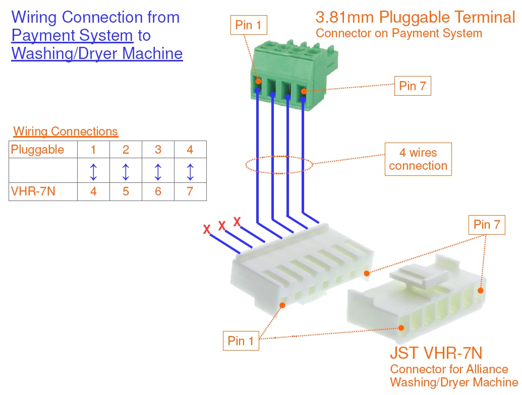
Wiring color code
The following is the propose color code of the wiring assuming that a CAT5e network cable is used.
Pluggable Screw Connector
CAT5e wire color code
VHR-7N Connector
Pin 1
Orange/White
Pin 4
Pin 2
Orange
Pin 5
Pin 3
Green/White
Pin 6
Pin 4
Green
Pin 7
Propose standardised color code for the wiring
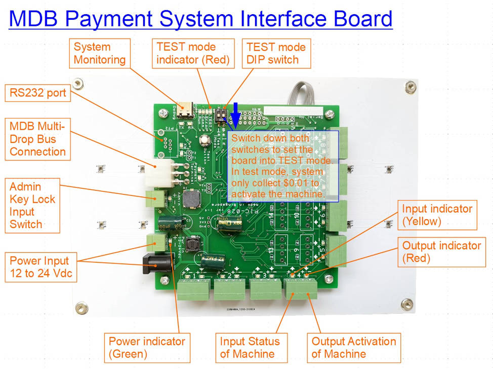
Board Description (MDB Payment Interface Board)
MDB Payment System Interface Electronic Circuit Board
There are two touch button assigned to the payment system to restart the system. It is usually the last button and the first button on the touch panel.
On a 8 machines payment board set, the default buttons are W4 (last button), and D1 (first button). Simply press and hold W4, followed by pressing and holding D1 button. Hold both button until you hear a short beep, followed by a long beep, then you can release your finger.
You should be able to see the system doing a full power off, and on restart process.
For IUC180 payment terminal, you will need to wait for about 10sec before terminal is ready for use.
For IM30 payment terminal, you will need to wait for about 2-3 minutes for the terminal to establish the internet connection before you can start using it.
Video demonstration of restarting the payment system.
Clearing Credits on the Washing Machine
This procedure is for fast forwarding or skipping the washing machine operating procedure. This is needed to help clear the credit triggered on the machine.
A quick paragraph to summaries the procedure. Simply ensure that the bypass switch is activated (disconnected or open circuit), press and hold button 1 & 2 to enter into the maintenance mode “rAPd”. Press “Start” button until the whole process ends.
The detailed procedures and explanation is as follows,
When the machine is idling, the display panel shows “100” indicating the credit of $1.00 required to start the machine.
After the payment, the machine will response with a beep with number changed to 30 (representing 30min of washing) This indicate that the machine has accepted the payment.
Open the front panel with a physical key.
Disconnect the bypass switch. This bypass switch allow us to go into the maintenance mode. With the machine bypass activated, it will also not record any transaction or operation to this machine. If you can see a sensor switch which detect the panel open, this is also known as the bypass switch. The washer (left side), dryer machine (right side), each has their own by pass switch.
Press and hold button 1 & 2 (the left side buttons, top and button). It will go into maintenance mode with the panel displaying “rAPd“.
The front loading door has to be close in order for the machine to cycle through the wash cycle.
Press the green Start button to fast forward the whole washer process. This reduces the timing on the machine. You will see the number 30min reducing. Keep on pressing until the value becomes 1, then wait for a few second for the machine to react, and a final press will get the machine time to becomes 0.
Open the door to complete the whole process. The washing machine will reset back to machine idling state. This panel will display “100” again, and the machine status will become available for the next transaction to take place.
Do remember to restore back the bypass switch before leaving the place. Test to check that the machine cannot enter into the maintenance mode by press holding the button 1 & 2.
Price Settings on the Washing Machine
Open the door for 2 sec and close it back to go into the configuration mode.
Press and hold button 1 & 2.
You will enter into “rAPd” menu. It is a bypass operation.
Press button 3 & 4 (up/down button) to scroll through the menu.
Scroll to the menu item Prog. Then press button 5 to enter.
Scroll to the menu item AtS, then press enter.
Scroll to the menu item 0, then press enter.
Then the price setting will be displayed. Example for $1, it will be 0100.
Press button 3 & 4 to change the price.
Press enter to go to the next digit until the price is entered.
Then press button 2 (back key) to escape all the way to the operation mode.
Troubleshooting Problems
Error messages on the payment terminal iUC180
“REFUSED (XX) REMOVE CARD“ Network connection issue with the payment. Resolved by resetting the payment terminal, or do a manual settlement to see if the problem go away.
A “Sound Audio Detector” is a device or software application designed to detect, analyze, and sometimes interpret sounds within its vicinity. These detectors are utilized in various fields for a multitude of purposes, ranging from security and surveillance to scientific research and entertainment.
Audio detector detects audio sound from an audio input and switch on a relay output. The relay can be used as an output to trigger/switch on devices like light indicators, motors, lock and other electrical appliances.
Detector can detect signal from an audio line input, and convert it into an relay output to switch on another appliances/system in a very quiet environment or a very noisy zone.
This alternative notification provides an additional means of alarm alert for the users or operators.
Application
Detects audio and trigger output in a quiet environment.
Alarm alert for hearing impaired individual
Convert audio alarm into other forms of alert notification in a very noisy environment.
Security and Surveillance: Sound detectors are commonly used in security systems to identify and alert operators to potential threats or unauthorized activities. They can recognize sounds such as breaking glass, footsteps, or alarms.
Environmental Monitoring: In scientific research and environmental monitoring, sound detectors are employed to track wildlife activity, measure noise pollution levels, and monitor natural phenomena like earthquakes or volcanic eruptions.
Industrial Applications: Sound detectors play a crucial role in quality control processes within industries. They can detect abnormal sounds in machinery, indicating potential malfunctions or maintenance needs.
Smart Homes: Integrated into smart home systems, sound detectors can recognize voice commands for home automation or security purposes.
Entertainment: Sound detectors are utilized in interactive installations, gaming, and virtual reality applications to enhance user experiences by responding to specific sounds or creating immersive audio environments.
In essence, sound audio detectors serve as valuable tools across a diverse array of fields, offering real-time monitoring, analysis, and interpretation of sound data for various applications, from security and surveillance to scientific research and entertainment.
MDB (Multi-Drop Bus) is a standard communication protocol that is used in the vending machine industry. The communication between the many devices on the vending machines uses MDB. Another common standard for Japan’s vending machine is VCCS.
MDB communication is coordinated by a main VMC (Vending Machine Controller). It is the central place where all the connected MDB devices are connected to. VMC will control and get status of all the connected MDB devices.
Typical device inside a vending machine that uses MDB are,
Cashless Device (Cashless Card Payment Terminal)
Changer
Communication Gateway (Internet network)
Display
Energy Management System
Bill Validator
Universal Satellite Device
Coin Hopper or Tube
Age Verification Device
MDB Cashless Device Standard Payment Process
The procedure of a standard vending payment process perform by a standard MDB Cashless Card Payment Terminal is as follows,
Customer will tap their card on the payment terminal to begin the transaction. This process will trigger the vending machine to wake up, and present the customer with a range of choices that can be selected on the vending machine.
Next, the customer will make their selection from the range of available choices.
Once the choice is made, the payment terminal will receive the amount that needs to be collected from the customer. The amount to be collected is displayed on the payment terminal.
The customer will review the price amount. If the amount is correct, the customer can proceed to make the payment by tapping with their card again on the terminal.
If the payment is successful, the payment terminal will inform the vending machine that the payment is received. The machine will then proceed with what the customer wanted.
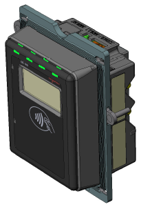
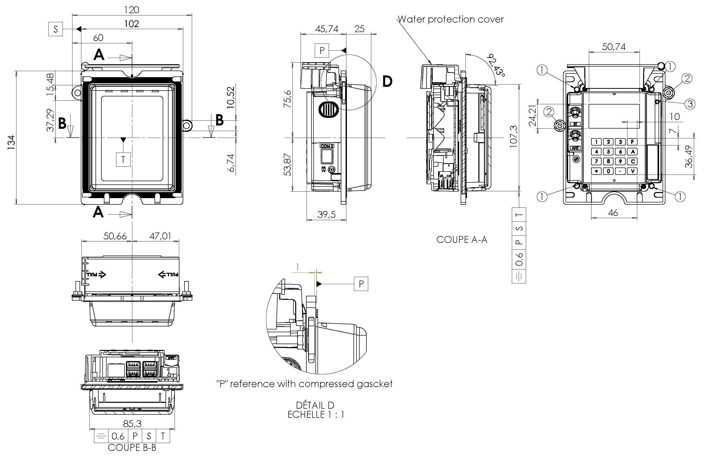
iUC180 Payment Card Reader Terminal for cashless card payment in Singapore. This wireless card terminal is very compact in size.
The terminal is designed with a EVA mounting standard. The standard standardise and simply the terminal device mounting work.
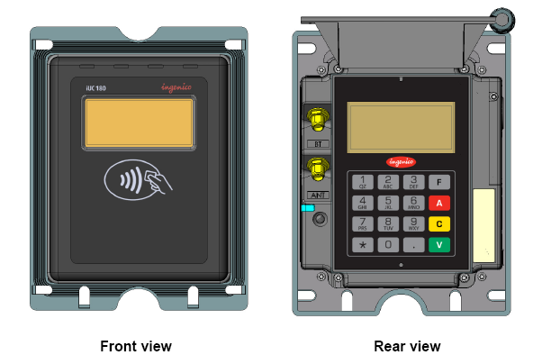
The following presents the dimension and size of the card payment reader terminal so that you can have some idea how it can fit into your vending or gaming machines.
Card terminal perspective view.
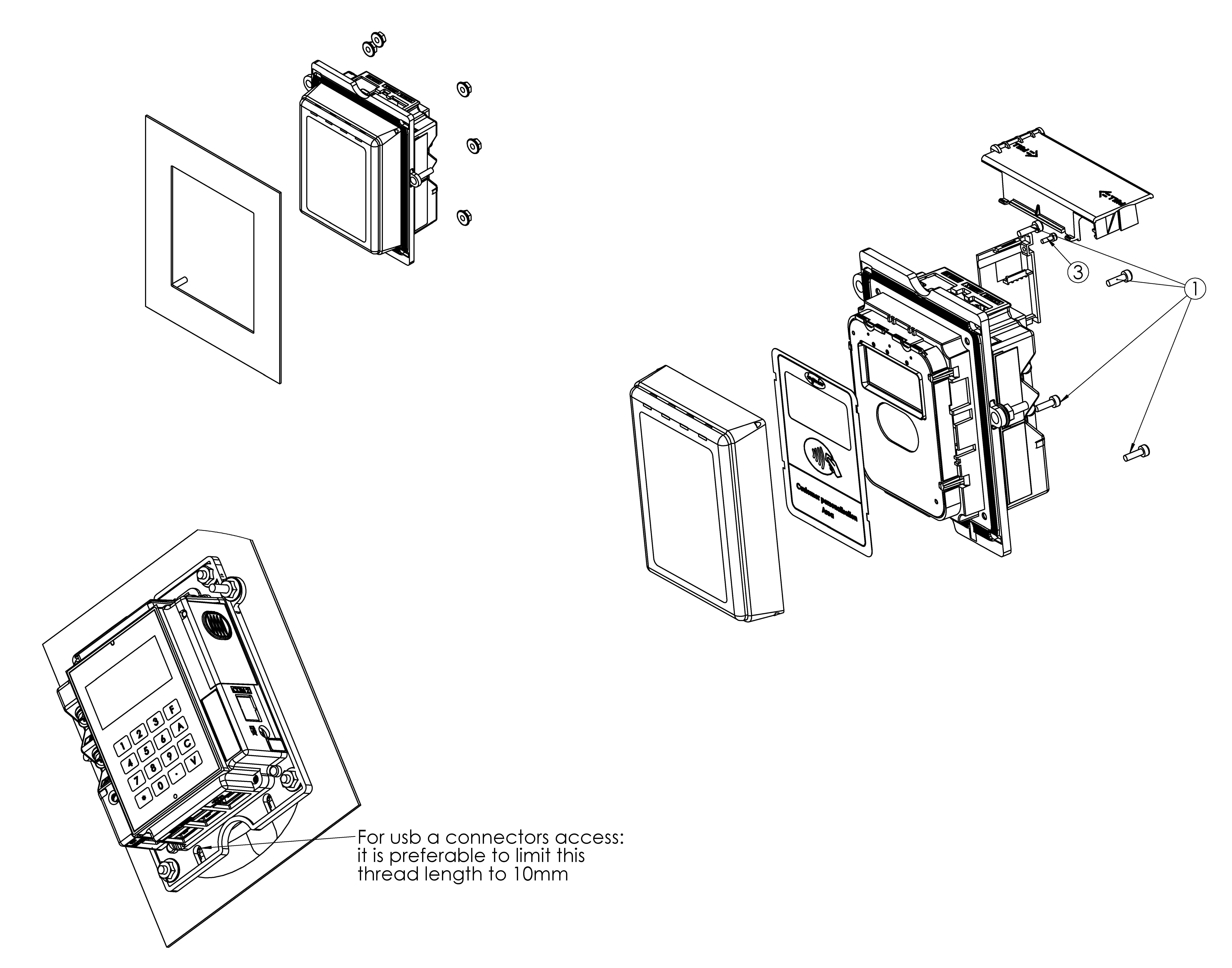
Exploded view.
Card Terminal Dimension
The card terminal measures about 102x134x71mm.
Card Payment Terminal Dimension Size
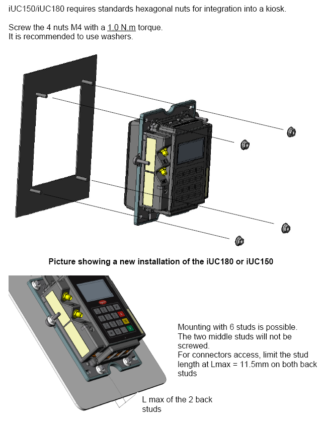
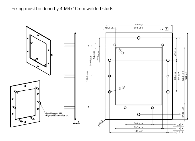
Propose Mounting Bracket for Payment Terminal
Propose 4x M4 studs at the corner, forming a rectangular shape. To be secure by nuts.
Recommended mounting through the 4x M4 studs.
Propose Mounting Bracket Dimension
Mounting bracket studs size and position
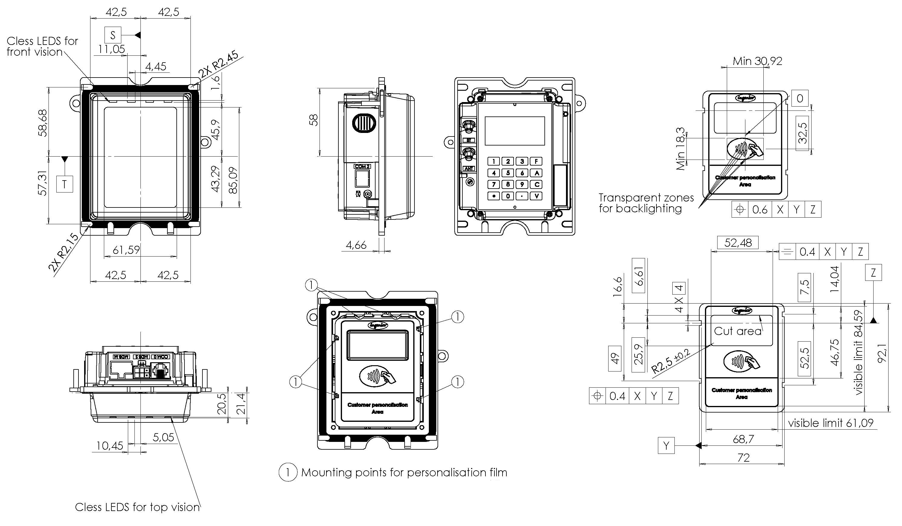
Card Terminal Labeling Dimension
Terminal Casing Customisation
Check out our card payment terminal rental package which includes our standard fabricated casing for your vending or gaming machines. This rental package is design for businesses to cap unforseen operating cost expense relating to the payment terminal.
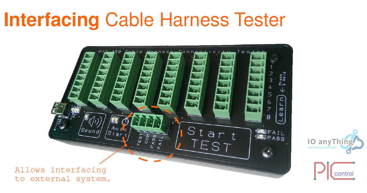
The cable tester is functional without connecting to external devices or system.
A 4 pins connector (green pluggable terminal connector) is available to allow custom connection to your own device or equipment. This connector is isolated via an optocoupler. This isolation will protect the tester from damage due to any wrong external connection.
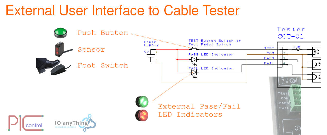
Custom User Interface to Cable Tester
The simple interface can be a switch and LED indicator. You may want to use your own foot padel switch to start the wiring connection test or may have your own indicator panel for your operator use.
You can adopt to the following connection.
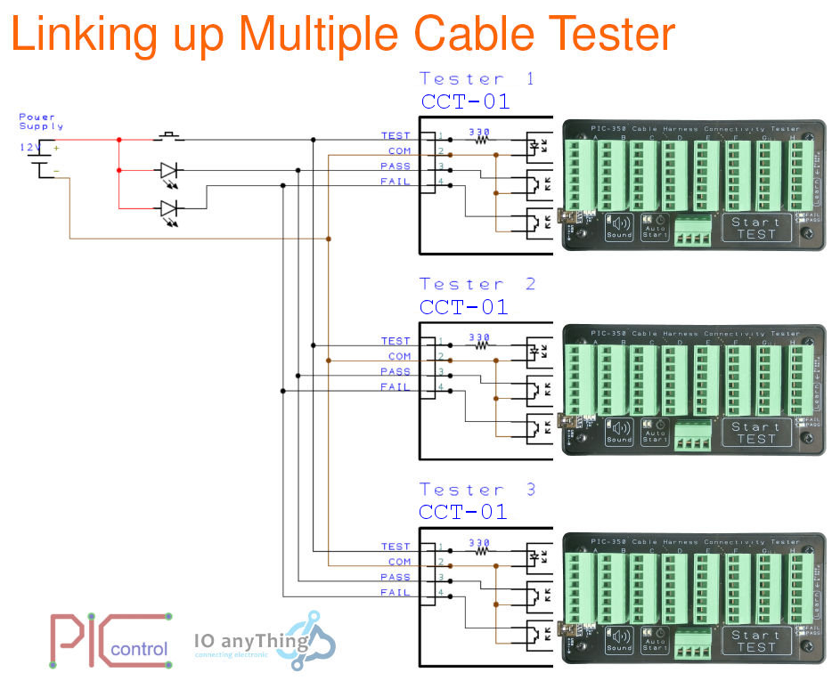
Multiple Cable Tester Linking Together
For some situation, this tester may not have enough test point for your cable harness. Each tester can only connect up to 64 connection points. If your connect has more than 64 points that you want to test in one shot, you can consider interfacing them in parallel as shown in the diagram.
This connection allows you to test cable harness with many connection points at the same time. It will allow a single test switch to trigger the tester. Any fault detected from one of the testers, it can drive your external indicator.
*** Please note that the test connection points are not inter-connected between the individual tester modules. Just take note to connect only groups of wires that are inter-connected together within a single tester.
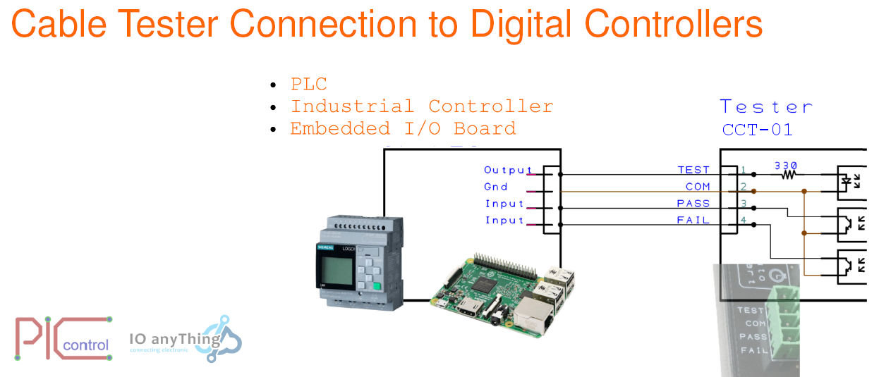
Digital Controller Connection
The tester can also be connected to your digital logic controller for more custom/complex control of your entire system.
The connection has a opto-coupled design. This will ensure that the tester will not cause interference issue to your controller or be affected by any external controller interfacing.
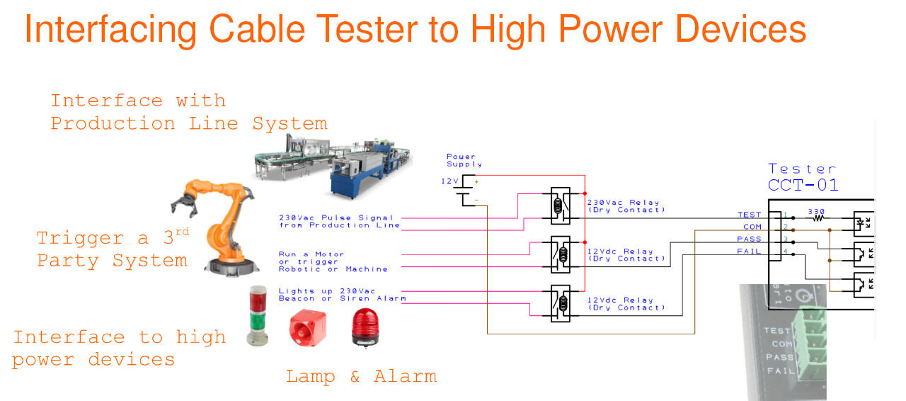
Interfacing to High Power Devices
For interfacing to high power devices, it is recommended to have a relay as the interface to isolate from the tester. The optocoupler built inside is meant to protect the tester. It cannot be used to drive a high current. Any current higher than 0.1A, it is recommended that a bigger relay is used for the interfacing.
The following is an example of the connection you can do to drive high power devices.
Are you looking for a tools that can help you identify and trace out the connection from your complex chunck of cable & harnesses with a press of a button?
Get hold of this awesome engineering tool for your electronic lab.
This tester maps out the connection of your cable saving you time and provide you with accurate results.
Advantage
Generate a comprehesive pin to pin connection report.
Fast.
Accurate connectivity report.
No more human error in your diagnosing of the cable wires connection.
Decide complex wiring connection.
Examine the pin connection at a glance through the generated mapped connection report.
Automatically mapped out all the wiring on the cable for you. You do not have to trace each pin connection one by one. You will get instant result through the generated test report.
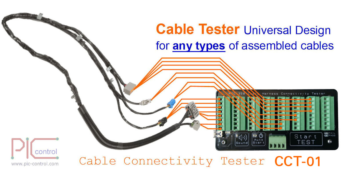
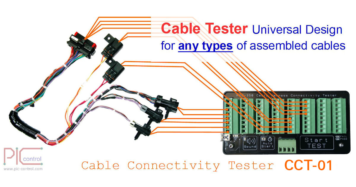
No matter how complex your cable or harnesses is, the process of decoding your wire connection is still the same.
Simply connect each connector pin wire to one of the terminal on the PIC-350 connection decoder, it will automatically trace, identify and mapped out all the connection for you.
The only thing you need to do it to analyse the generated report and document the results.
Simple. No more painstaking connection measurement, checking pin by pin manually using a multimeter.
PIC-350 is an awesome and smart X-ray tool for your cable wires reverse engineering work.
A productivity tool that an electronic engineer will keep on their engineering work bench.
A great tool to discovery the connection of a new or unknown cable. Can also be use for trace passive connection on your PCB circuit board.
– Cable connection reverse engineer tools – Cable connection tracer, mapping – Auto mapping of complex cable wiring connection. – Auto detection of wiring connection