Loading Arduino Bootloader to brand new ATMEL Microcontroller

This article is written as a guide to loading an Arduino bootloader or firmware onto a brand new ATMEL microcontroller IC chip.

When you first purchase a legitimate ATMEL ATMEGA16U2 chip, it is actually loaded with a default DFU firmware. If you did not purchase the microcontroller from the legitimate source, there might not be any firmware pre-loaded inside. In this case, you can only load the bootloader firmware using the ATMEL ICSP programmer method.

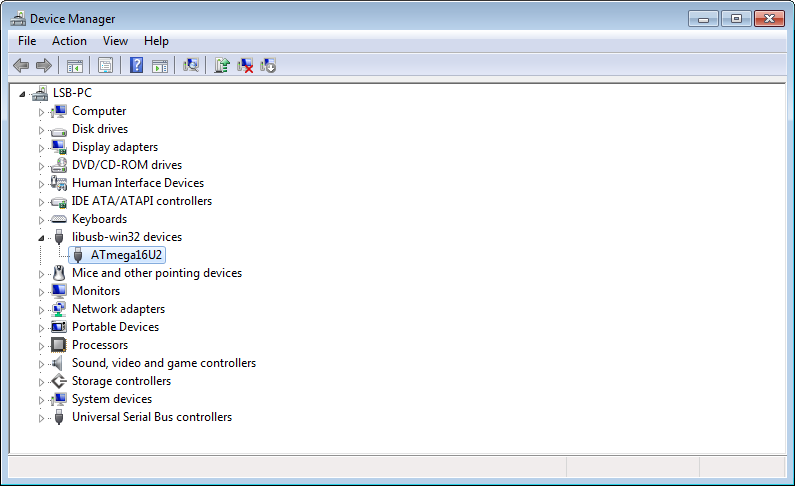
If you built the basic USB circuit using the ATMEL microcontroller and plugged it into your computer’s Windows Operating System (example Win7), you should be able to see a USB device name “ATmega16U2” under a folder libusb-win32 devices in the Win7 Device Manager.

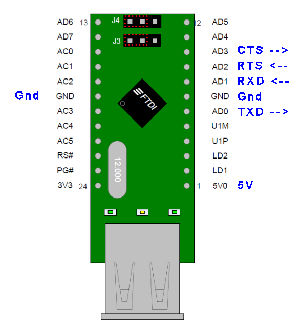
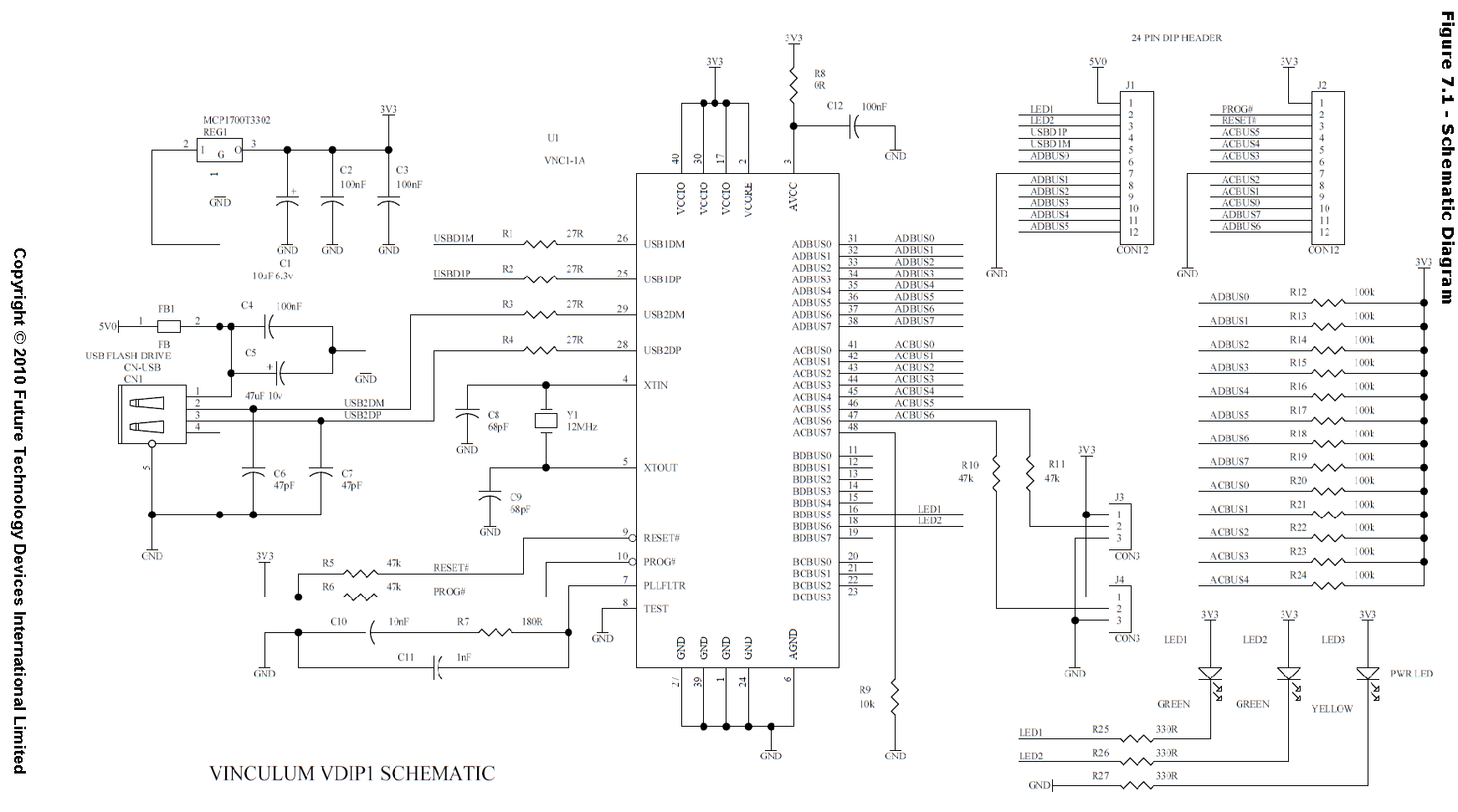
Basic USB circuit for ATMEGA16U2

Basic USB circuit using ATMEGA16U2 microcontroller from AMTEL.
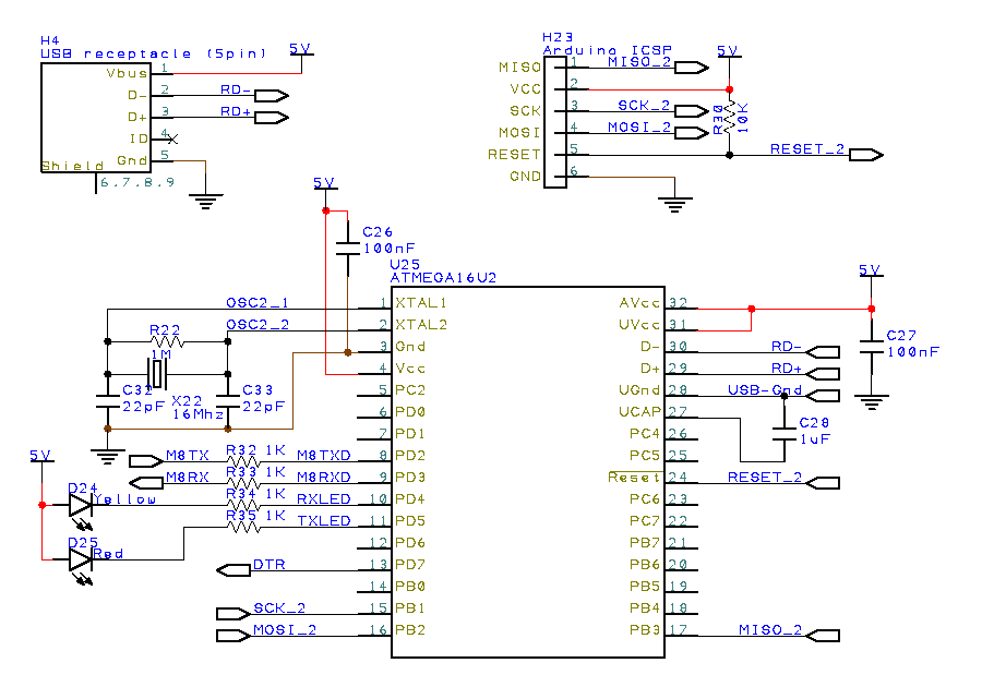
Click to enlarge the basic USB ATMEGA16U2 schematic circuit.

Using the ATMEL FLIP software, you will be able to load firmware or bootloader using its default ATMEL DFU bootloader. You can download this FLIP software from ATMEL website. Or you can download here,

Uploading Arduino USB Serial Firmware via FLIP

  1. Plug the USB circuit to your computer. You should see the ATmega16U2 device in the Win7 Device Manager. This is the default DFU firmware loaded in the ATMEGA16U2 microcontroller chip. It is also known as the DFU mode.
    ATmega16U2 in Device Manager
  2. Install and execute ATMEL FLIP software.
  3. Select the microcontroller. Click “Device”>”Select…”, or use the shortcut key <Ctrl>+S. Select the microcontroller “ATMEGA16U2”.
  4. Select the communication. Click “Settings”>”Communication”>”USB”, or use the shortcut key <Ctrl>+U.
  5. A dialogue box may appear. Then click open.
  6. Download this USB serial firmware for ATMEGA16U2. For ATMEGA8U2, you can download the USB serial firmware here.
  7. Load the firmware on the FLIP software. Click “File”>”Load HEX File…”>”Arduino-usbserial-atmega16u2-Uno-Rev3.hex”
  8. Ensure the check box is checked. “Erase”, “Program” and “Verify”
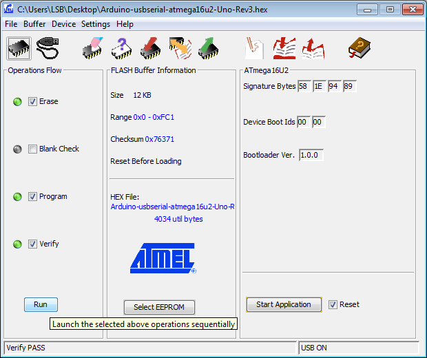
    ATMEL FLIP software interface loading Arduino USB serial firmware to ATMEGA16U2
  9. Click “Run”.
  10. Once the firmware is loaded, you can unplug the USB connection and plugged it back to your computer. You should be able to see in your device manager as “Arduino Uno” under the section “Ports (COM & LPT)” instead of the previous “ATMEGA16U2” device.
    Arduino UNO ini Device Manager
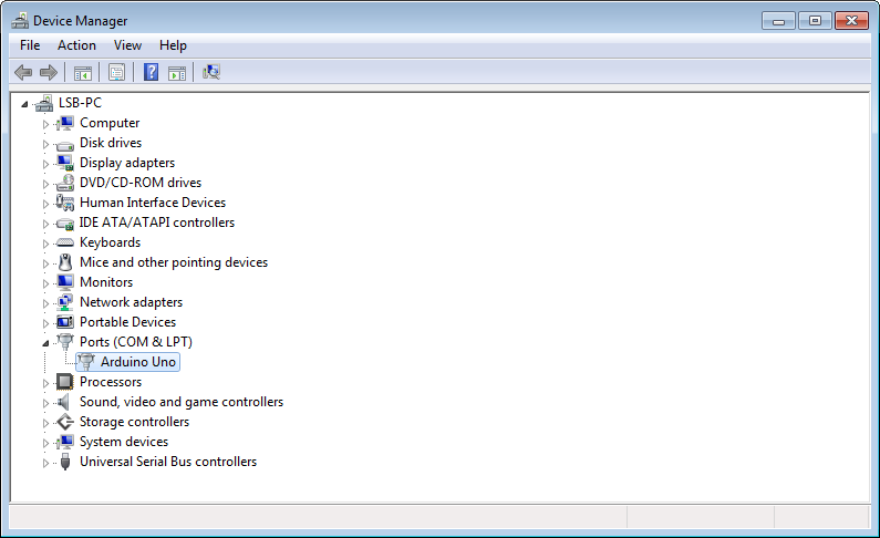
  11. The ATMEGA16U2 is now loaded with the USB serial firmware which is used in a typical Arduino UNO board. Your ATMEGA16U2 microcontroller is now a USB serial (CDC) or USB to serial communication converter. The same converter IC chip used in Arduino UNO board.

Upload DFU Bootloader to brand new ATMEL USB Microcontroller

For the ATMEL microcontroller which does not have the default DFU firmware pre-load into it, you can load the following DFU hex file for the respective ATMEL microcontroller chip.

Since the microcontroller does not have a bootloader, the only way to load this DFU to the microcontroller via an ATMEL ICSP programmer. The instruction guide for the uploading of a firmware using an ICSP programmer can be found here.

Upload Arduino Bootloader into ATMEGA328P Microcontroller

For the ATMEL Microcontroller ATMEGA328P used in Arduino UNO, the Arduino bootloader can be upload using an Arduino ICSP programmer with the Arduino IDE (integrated development environment) Software.

  • Run the Arduino IDE software.
  • Select “Arduino UNO” from the Tools > Board menu.
  • Select “ArduinoISP” from Tools > Programmer (depending on the programmer that you are using)
  • Run Tools > Burn Bootloader

Now your ATMEGA328P microcontroller is loaded with the Arduino bootloader firmware.

Take Note for ATMEGA328 Microcontroller

Uploading of  bootloader for ATMEGA328 (signature ID 0x1e 0x95 0x14)  is different from ATMEGA328P (signature ID 0x1e 0x95 0x0F).

Check out the following webpage if you want to upload the bootloader to ATMEGA328.

Other Arduino Related Services

AC-DC Power Supply

power supply open frame

AC-DC Power (Meanwell open-frame G3 series) meanwell power supply

  • 110-230Vac input

AC-DC power supply 15W in SingaporeAC-DC power supply 75W in Singapore

Model for Meanwell
AC-DC Power Supply
Voltage Output Current (maximum) Size (mm)
RS-15-3.3 3.3V 3.0A 51 x 62.5 x 28 mm
RS-25-3.3 3.3V 6.0A 51 x 78 x 28 mm
RS-35-3.3 3.3V 7.0A 82 x 99 x 36 mm
RS-50-3.3 3.3V 10A 97 x 99 x 36 mm
RS-75-3.3 3.3V 15A 98 x 129 x 38 mm
RS-100-3.3 3.3V 20A 97 x 159 x 38 mm
RS-150-3.3 3.3V 30A 98 x 199 x 38 mm
Voltage Output Current (maximum) Size (mm)
RS-15-5 5V 3.0A 51 x 62.5 x 28 mm
RS-25-5 5V 5.0A 51 x 78 x 28 mm
RS-35-5 5V 7.0A 82 x 99 x 36 mm
RS-50-5 5V 10A 97 x 99 x 36 mm
RS-75-5 5V 12A 98 x 129 x 38 mm
RS-100-5 5V 16A 97 x 159 x 38 mm
RS-150-5 5V 26A 98 x 199 x 38 mm
Voltage Output Current (maximum) Size (mm)
RS-15-12 12V 1.3A 51 x 62.5 x 28 mm
RS-25-12 12V 2.1A 51 x 78 x 28 mm
RS-35-12 12V 3.0A 82 x 99 x 36 mm
RS-50-12 12V 4.2A 97 x 99 x 36 mm
RS-75-12 12V 6A 98 x 129 x 38 mm
RS-100-12 12V 8.5A 97 x 159 x 38 mm
RS-150-12 12V 12.5A 98 x 199 x 38 mm
Voltage Output Current (maximum) Size (mm)
RS-15-15 15V 1.0A 51 x 62.5 x 28 mm
RS-25-15 15V 1.7A 51 x 78 x 28 mm
RS-35-15 15V 2.4A 82 x 99 x 36 mm
RS-50-15 15V 3.4A 97 x 99 x 36 mm
RS-75-15 15V 5.0A 98 x 129 x 38 mm
RS-100-15 15V 7.0A 97 x 159 x 38 mm
RS-150-15 15V 10A 98 x 199 x 38 mm
Voltage Output Current (maximum) Size (mm)
RS-15-24 24V 0.6A 51 x 62.5 x 28 mm
RS-25-24 24V 1.1A 51 x 78 x 28 mm
RS-35-24 24V 1.5A 82 x 99 x 36 mm
RS-50-24 24V 2.2A 97 x 99 x 36 mm
RS-75-24 24V 3.2A 98 x 129 x 38 mm
RS-100-24 24V 4.5A 97 x 159 x 38 mm
RS-150-24 24V 6.5A 98 x 199 x 38 mm
Voltage Output Current (maximum) Size (mm)
RS-15-48 48V 0.3A 51 x 62.5 x 28 mm
RS-25-48 48V 0.57A 51 x 78 x 28 mm
RS-35-48 48V 0.8A 82 x 99 x 36 mm
RS-50-48 48V 1.1A 97 x 99 x 36 mm
RS-75-48 48V 1.6A 98 x 129 x 38 mm
RS-100-48 48V 2.3A 97 x 159 x 38 mm
RS-150-48 48V 3.3A 98 x 199 x 38 mm
Positive Negative Supply Voltage Output Current (maximum) Size (mm)
RQ-50B ±5V, ±12V 1.0A per output 97 x 99 x 36 mm
RQ-50C ±5V, ±15V 1.0A per output 97 x 99 x 36 mm
UPS (SLA battery) Voltage Output Current (maximum) Size (mm)
AD-55A 13.8V (adjustable) 4A 97 x 152.5 x 38 mm
SCP-35-12 13.8V (adjustable) 2.6A 99 x 97 x 36 mm
SCP-50-12 13.8V (adjustable) 3.6A 129 x 98 x38 mm
SCP-75-12 13.8V (adjustable) 5.4A 159 x 97 x 38 mm
 AC-DC UPS power supply for SLA battery in Singapore  AC-DC UPS power supply for SLA battery in Singapore
Motor Power Supply Voltage Output Current (maximum) Size (mm)
EDR-7548
(EDR-75 series power supply for running motor)
48V 1.6A 35 x 125.2 x 102 mm
 AC-DC pwoer supply for motor in Singapore Especially suitable for motor where it may at times draw high current which may activate the protective feature of a normal power supply.


Meanwell Power Supply Series

  • G3 Series (normal power supply)
  • NE Series
  • SE Series (Withstand 300Vac surge input for 5 sec)
  • PFC Series (built-in active Power Factor Correction)
  • Harsh Environment Series
  • DIN Series (DIN rail mount)
  • Security Series (Power Supply with UPS function, Battery Charger), AD-55A
  • DC-DC Converter Switching Power Supply
  • Industrial Adaptor

Mechanical Prototyping Resources

Mechanical design and manufacturing companies providing mechanical part fabrication and prototyping in Singapore. CNC machining.

Mechanical Design Companies in Singapore

The following companies provide high end mechanical enclosure design in Singapore. If you are looking for designing enclosure for your mass production purpose, check out these design companies in Singapore.

Mechanical Prototyping Companies in Singapore

Laser Cutting and laser marking service companies in Singapore

Laser Cut for Stainless Steel Sheet Metal

Silkscreen Printing Service in Singapore

Stencil

Workshop

Others

You may also like to check out this mechanical material engineering services and resources or mechanical screws supplier in Singapore.

Click here for electronic product prototyping and development services in Singapore.

Serial Communication Standard Protocol

Most of the standard is a derivative of a formal mature technology. The following introduces the serial communication the is commonly used in the industries. Most of them are fairly similar but are known as a different name.

Common Physical Communication Layer

  • UART (0-5V, 0-3.3V)
  • RS232
  • RS485, RS422
  • Ethernet
  • USB
  • KNX/EIB
  • LIN (for automotive single wire)

Other Physical Communication Layer

  • RF

Protocol Layer on the common Physical Layer

Protocol layer is the data byte format design for a certain method of communicating. The protocol layer make use of the physical layer to send the data over a communication channel.

The following are some

  • Modbus (uses RS485, RS232 or Ethernet)
  • CAN bus (uses RS485)
  • MDB, Multi Drop Bus protocol (uses 9 bits RS232/RS485)
  • Multi-Master Bus

Other Protocol Layer

  • WiFi
  • Zigbee
  • Xbee
  • Zwave
  • Bluetooth

PCB Standoff

PCB Standoff

  • Brass (most common)
  • Plated Steel
  • Nylon

brass PCB standoff     Nylon PCB standoff

These PCB standoffs available in brass, steel or nylon material. The threaded ends are for typically M3 and M4 screw size. One side can be a male thread and the other end a female thread. Both end female thread is also quite common. The standoff length is usually in millimetres (even number, example: 4mm, 6mm, 8mm, 10mm, 12mm, etc…

Nylon is light in weight and has a non-magnetic property like brass. Screws and nuts are also available.

PCB Standoff Base

The PCB standoff base can be secured underneath the PCB board and provide your board with the support. This can lift up the PCB board so that the bottom side will not be touching the table surface. This is useful especially if the table is metallic or there are many metal parts laying around. A simple standoff base will reduce the chance of accidental short-circuit, without having to spend time and money on a casing.

These bases come with a double sided adhesive tape below. It allows you to secure it onto a casing or a surface plate easily.

Adhesive Standoff Base with M3 nut thread for securing to PCB board

PCb Standoff Base (Black color, M3)     PCB Standoff Base illustration

Screwless Standoff Base

Nylon PCB Standoff base for hole size 4mm         PCB Standoff Base illustration     Nylon PCB Standoff base

背胶固定座 PCB M3

SMD PCB Standoff / Spacer (surface mount)

https://www.dmtl.co.uk/product-series/smd-pcb-spacers-standoffs-power-elements-for-high-current-applications-smt-terminal-blocks

USB Thumbdrive Logger using VNC1L chip (VDIP1)

VDIP1 USB module is base on VNC1L from FTDI Chip.

VDIP1 module product using VNC1L chip from FTDI Chip

VDIP1 Pinout & Settings

VDIP1 Pinout and connection details

  • Set jumper to UART (J3=J4= 2+3), as shown by the Red dotted rectangular box in the picture.
  • Default UART configuration: baudrate 9600bps, 8 data bits, 1 stop bit, no parity
Pin 015V
Pin 06TXD (UART data output)
Pin 07Gnd
Pin 08RXD (UART data input)
Pin 09RTS (VNC1L can only accept incoming data when RTS is low)
Pin 10CTS (tie to Gnd to permanently request send data into VNC1L chip)
Pin 18Gnd
Pin 22!Reset (A reset pin)

VDIP1 schematic taken from the datasheet.

VDIP1 schematic

VNC1L chip datasheet.

VNC1L chip command.

VNC1L Logger Application Notes.

Download test script for VDIP1 module using docklight.


Comments

every command must end with 0x0D

VDIP1 Evaluation

1) When VDIP1 is powered up, it will send out the following text
-> “<CR>Ver 03.68VDAPF On-Line:<CR>”

2) When a thumdrive is connected
-> “Device Detected P2<CR>
No Upgrade<CR>
D:\><CR>”

3) When ascii command DIR<CR> is issued.
-> <CR>
SYSTEM~1 DIR<CR>
D:\><CR>

Short command evaluation (Hex data)

1) Check for presence of a disk
(when there is no thumbdrive plugged in)
Send    -> 0D
Receive <- “No Disk<CR>”

(when there is thumbdrive plugged in)
Send    -> 0D
Receive <- “D:\><CR>”

2) Switch to short command mode.
Send    -> 10 0D
Receive <- 3E 0D (mean command accepted)

3) Repeat command checking for presence of a disk (in short command mode)
(when there is thumbdrive plugged in)
Send    -> 0D
Receive <- 3E 0D

When thumbdrive is unplugged
Receive <- 44 52 32 0D    “DR2<CR>”     (slave device removed from port 2)
Receive <- 4E 44 0D    “ND<CR>”    (no disk)

(when there is no thumbdrive plugged in)
Send    -> 0D
Receive <- 4E 44 0D    “ND<CR>”

Sounder and Beacon Alarm Alert

Klaxon Sounder Beacon Products.

  • Dustproof and waterproof (IP65 for deep base version).
  • 32 Sound Tones to choose from.
  • Volume control.
  • Red/Amber Beacon light.
  • Quick and simple to install.

Suitable for Fire alarm alert, hazardous area, security public warning, railway and marine.

Sounder

Sound alarm as an alert to passerby people. Sound range about 10-50m on an open space outdoor environment.

Sounder IP65

Sounder product brochure (sounder-sonos.pdf)

Sounder Beacon

Visual alert with sound alarm and a strobe light to warn people about the danger ahead or hazard work in progress.

Sounder Beacon (IP65)

Sounder Beacon product brochure (sounder-beacon-sonos.pdf)

Alarm Tone to choose from

Click on the following sound file to listen to the range of alarm tone that you can select from your sounder beacon.

  1. audio alarm-tone01.mp3
  2. audio alarm-tone02.mp3
  3. audio alarm-tone03.mp3
  4. audio alarm-tone04.mp3
  5. audio alarm-tone05.mp3
  6. audio alarm-tone06.mp3
  7. audio alarm-tone07.mp3
  8. audio alarm-tone08.mp3
  9. audio alarm-tone09.mp3
  10. audio alarm-tone10.mp3
  11. audio alarm-tone11.mp3
  12. audio alarm-tone12.mp3
  13. audio alarm-tone13.mp3
  14. audio alarm-tone14.mp3
  15. audio alarm-tone15.mp3
  16. audio alarm-tone16.mp3
  17. audio alarm-tone17.mp3
  18. audio alarm-tone18.mp3
  19. audio alarm-tone19.mp3
  20. audio alarm-tone20.mp3
  21. audio alarm-tone21.mp3
  22. audio alarm-tone22.mp3
  23. audio alarm-tone23.mp3
  24. audio alarm-tone24.mp3
  25. audio alarm-tone25.mp3
  26. audio alarm-tone26.mp3
  27. audio alarm-tone27.mp3
  28. audio alarm-tone28.mp3
  29. audio alarm-tone29.mp3
  30. audio alarm-tone30.mp3
  31. audio alarm-tone31.mp3
  32. audio alarm-tone32.mp3


LCD Display Alphanumeric & Dot Matrix

Commonly available LCD display (alphanumeric, dot matrix) configuration and dimension.

Alphanumeric LCD Display (16 x 2, 1602)

2.95 x 5.15mm character size, 16 Chars x 2 Lines. Commonly available.

16x2 Alphanumeric LCD Display
16x2 Alphanumeric LCD Display dimension

Pin-out

Pin No.NameFunction
1Gnd
25V
3VEEContrast adjustment voltage
4RSRegister select (1=data, 0=instruction)
5R/!W1=read, 0=write
6EEnable
7D0Data bit 0
8-13D1-D6Data bit 1-6
14D7Data bit 7
15ALED + (Backlight)
16KLED – (Backlight)

Reference:

Alphanumeric LCD Display (20 x 4, 2004)

5mm character size, 20 Chars x 4 Lines (MIDAS LCD Display)

20x4 Alphanumeric LCD Display
20x4 Alphanumeric LCD Display dimension

Pin-out

same as the alphanumeric LCD display above.

Dot Matrix LCD Display (128 x 64, 12864)

128x64 Dot Matrix LCD Display
128x64 Dot Matrix LCD Display dimension
Pin No.NameFunction
15V
2Gnd
3V0Contrast adjustment voltage
4D0Data bit 0
5D1-D6Data bit 1-6
6D7Data bit 7
7CS2Chip select signal for IC2
8-13CS1Chip select signal for IC1
14!RSTReset Signal
15R/!W1=read, 0=write
16RSRegister select (1=data, 0=instruction)
17EEnable
18VEEContrast adjustment voltage
19ALED + (Backlight)
20KLED – (Backlight)

Check out the documentation for the display controller chip KS0108 or T6963c. Application notes for T6963c

Reference:

Raw LCD Display (TN, HTN, STN, FSTN LCD Display)

This screen module is typically has to be custom made. Each pixel is a patch of custom graphic. The advantage of use this raw display is the low power consumption.

The pin out will be unique to each custom display panel. The pins are usually consist of SEGMENTS and COMMONS. These are like vertical and horizontal pins which can allows time multiplexing of the pixel display to reduce the number of pins required.

The disadvantge of this display is the need to drive each pixel with an alternating voltage. This makes it troublesome to drive. A driver is usually used for this LCD interface. Example of a driver will be for example, HOLTEK HT1621B, HT1620, HT1621, HT1622, HT16220, HT1623, HT1625, HT1626.

Raw LCD Display

There is a term “bias”. This basically means the multiplexing. 1/2 means it is multiplexing 2 columns, 1/3 means multiplexing 3 columns. The more it multiplex, the quality (contrast) of the LCD display gets lower due to the lower display frequency. As long as the display frequency is >30Hz, you shouldn’t see any flickering.

For more raw LCD customise information, check out the following link.

http://www.displaybly.com/lcd-news/11-points-confirm-before-quote-a-custom-lcd-screen/

Other LCD driver

  • HT1621B (48 TSSOP)
  • tm1668
  • PCF8576 (56 TSSOP)
  • AY0438 (DIP-40)
  • PCF2100CT (SO28, 2COMx20SEG)
  • PCF2111T (VSO-40, 2COMx32SEG)
  • PCF2112C (VSO-40)

Simple LCD driver for 1x COM

  • 74HC164

Elastomeric Strips for raw LCD panel module

Elastomeric strips is a special rubber cushion material which acts as a cushion and conductor for tracks. It is often found with non-pins raw LCD module.

Rubber Strips on LCD panel module, Elastomeric strips

Design Resource for Electronics Engineer

Commonly Available Electronic Components for Design Engineers

This is the main reference page which provides a list of the commonly available electronic components, parts, accessories for your electronic design selection.

If you are an electronic designer, you are welcome to bookmark this page for your future design reference.

Connectors

Passive Components

Capacitor Types (selection)

  • Ceramic capacitor
  • Polymer capacitor
  • Film capacitor (Metallized film, Foil firm, Polypropylene film or PP film, Polyyester film, etc…)
  • Aluminum Electrolytic capacitors
  • Tantalum Electrolytic capacitors
  • Niobium Electrolytic capacitors
  • Super capacitor
  • Silver Mica capacitor
  • Variable capacitor
  • etc…


  • smd, surface mount
  • through hole
  • radial style
  • screw terminal

Display

Switches

  • Switches
  • PCB mount tactile switches
  • Metalic panel mount switches

Microcontrollers

PCB Accessories

Cable Selection Guide


AC Power Plug

  • UK Plug (3 pins)
  • EU Plug (2 pins)
  • IEC C13 plug (230Vac, 10A)
  • IEC C7 plug (230Vac, 2.5A)

Reference:

Product Accessories for Projects

Mechanical Resources

Software

Electrical Single Line Drawing Schematic Tools

Admin Tools

Others

Automated Awning Shade Wiring for Rain Sensor

Automated Awning Shade using a Rain Sensor

Automated awning will open its shade when the weather is raining, and retract the shade when the sky turns fine. A rain sensor is used to detect the rain. A switch can be wired for manual or automatic control of the motorised awning shade.

Automated Rain Sensor Awning Shelter.

Automated Awning Shade, Rain Sensor Wiring

An example of the automated awning rain sensor wiring for the automatic and manual control of the shade.

The cable to the outdoor rain sensor needs a minimum of 3 wires to work. A jumper wire can be wired inside the rain sensor to supply the 12V supply to the internal relay. This will enable the output (NO, normally open) to be energised when the rain sensor is activated. Hence a minimum of 3 wires is enough for the rain sensor. For a more flexible implementation, we will recommend 4-5 wires connection.

Check out the step by step rain sensor installation guide, for more details.

Automated rain sensor awning shelter wiring.

Rain Sensor Automated System Integration

Automatic rain sensing awning passenger waiting for a taxi


The automatic awning will be opened up when the rain sensor detects raining activity. The sensitivity of the rain detection can be adjusted.

If the rain activity has stopped, the awning will remain opened for about 2-3 minutes before it starts to retract the awning up. If a longer time period is needed, you can set the DIP switch no. 4 on the sensor to extend the resting time to 15 minutes.


Auto rain sensing or manual awning control switch


An operator can select “Auto” mode on the switch, which allows the rain sensor to open the awning automatically when it rains. The “Manual” mode allows the operator to manually open or retract the awning with the Up/Down switch on the righthand side.

You can refer to the wiring diagram as featured in the previous section above.

You may like to check a wireless or network rain sensor notification system for a more integrated information technology system.

Check out this page for more information about this wet weather rain sensor.

Rain Sensor

Contact PIC-CONTROL for a custom automated rain sensor control system today.