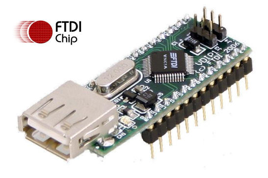
VDIP1 USB module is base on VNC1L from FTDI Chip.
VDIP1 Pinout & Settings
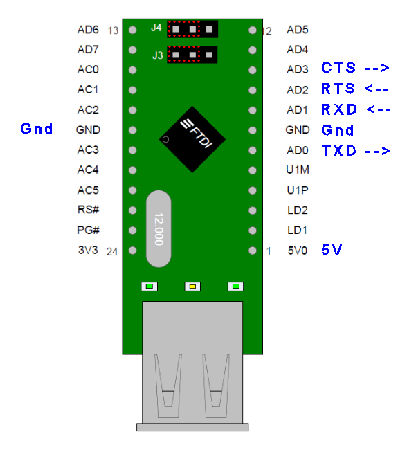
- Set jumper to UART (J3=J4= 2+3), as shown by the Red dotted rectangular box in the picture.
- Default UART configuration: baudrate 9600bps, 8 data bits, 1 stop bit, no parity
| Pin 01 | 5V |
| Pin 06 | TXD (UART data output) |
| Pin 07 | Gnd |
| Pin 08 | RXD (UART data input) |
| Pin 09 | RTS (VNC1L can only accept incoming data when RTS is low) |
| Pin 10 | CTS (tie to Gnd to permanently request send data into VNC1L chip) |
| Pin 18 | Gnd |
| Pin 22 | !Reset (A reset pin) |
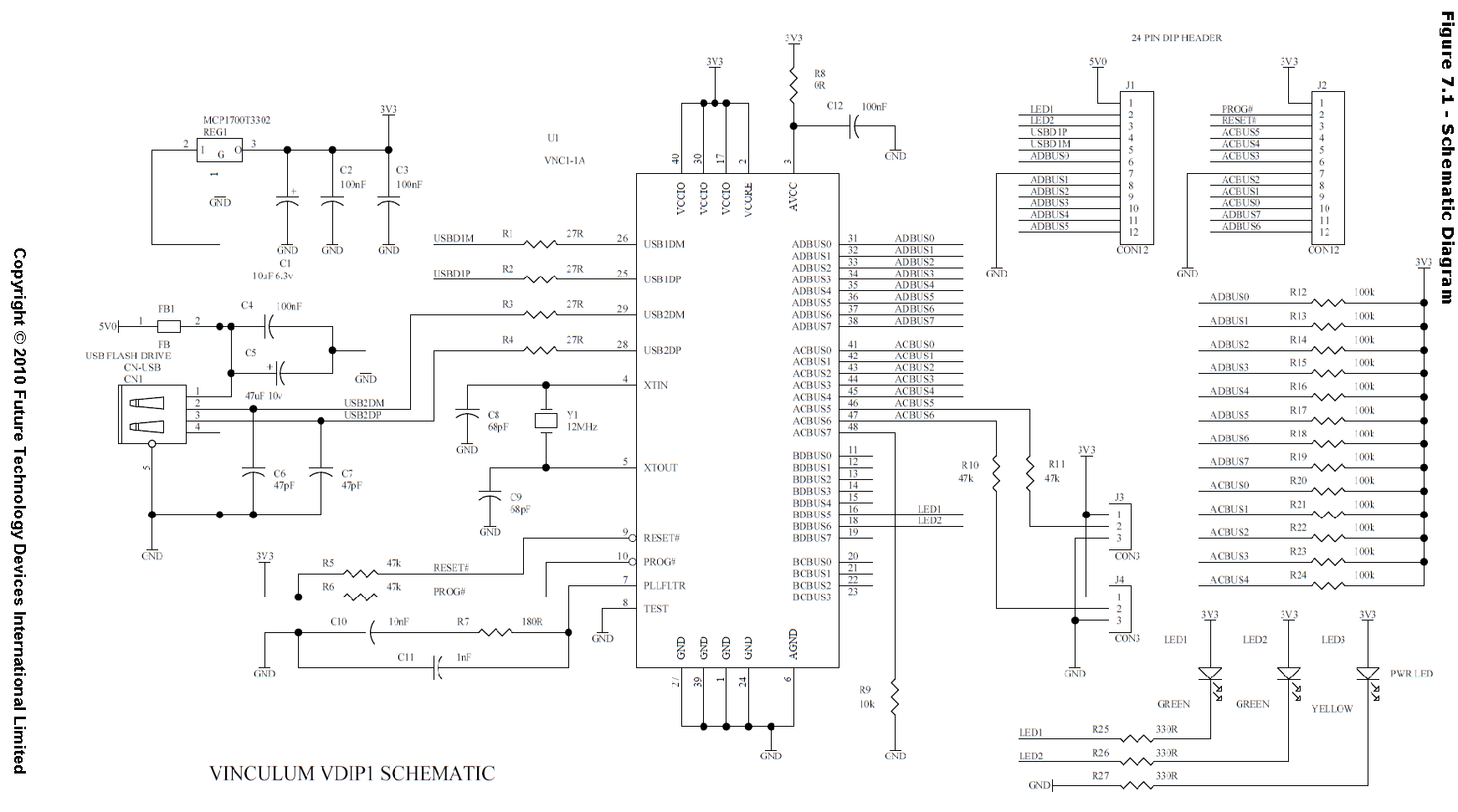
VDIP1 schematic taken from the datasheet.
VNC1L Logger Application Notes.
Download test script for VDIP1 module using docklight.
Comments
every command must end with 0x0D
VDIP1 Evaluation
1) When VDIP1 is powered up, it will send out the following text
-> “<CR>Ver 03.68VDAPF On-Line:<CR>”
2) When a thumdrive is connected
-> “Device Detected P2<CR>
No Upgrade<CR>
D:\><CR>”
3) When ascii command DIR<CR> is issued.
-> <CR>
SYSTEM~1 DIR<CR>
D:\><CR>
Short command evaluation (Hex data)
1) Check for presence of a disk
(when there is no thumbdrive plugged in)
Send -> 0D
Receive <- “No Disk<CR>”
(when there is thumbdrive plugged in)
Send -> 0D
Receive <- “D:\><CR>”
2) Switch to short command mode.
Send -> 10 0D
Receive <- 3E 0D (mean command accepted)
3) Repeat command checking for presence of a disk (in short command mode)
(when there is thumbdrive plugged in)
Send -> 0D
Receive <- 3E 0D
When thumbdrive is unplugged
Receive <- 44 52 32 0D “DR2<CR>” (slave device removed from port 2)
Receive <- 4E 44 0D “ND<CR>” (no disk)
(when there is no thumbdrive plugged in)
Send -> 0D
Receive <- 4E 44 0D “ND<CR>”