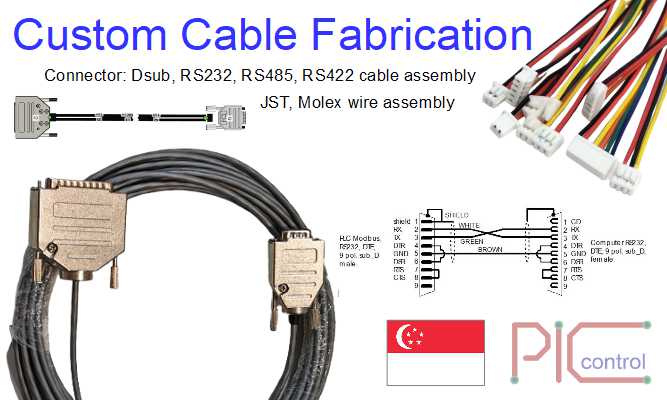
Our company provide custom cable fabrication and connector cable assembly services in Singapore.
The demand for custom cable fabrication and connector cable assembly has surged globally, driven by the growing need for specialized electronic components across various industries.
This article explores the key aspects of this industry, the processes involved in custom cable assembly, and the benefits of tailored solutions for diverse applications.
The Custom Cable Assembly Process
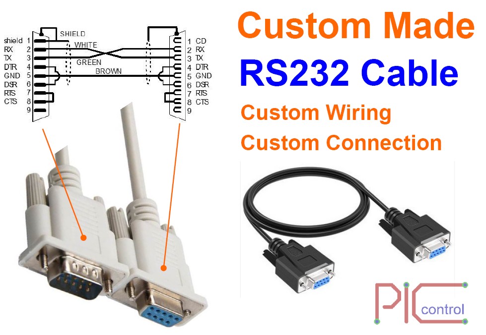
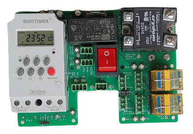
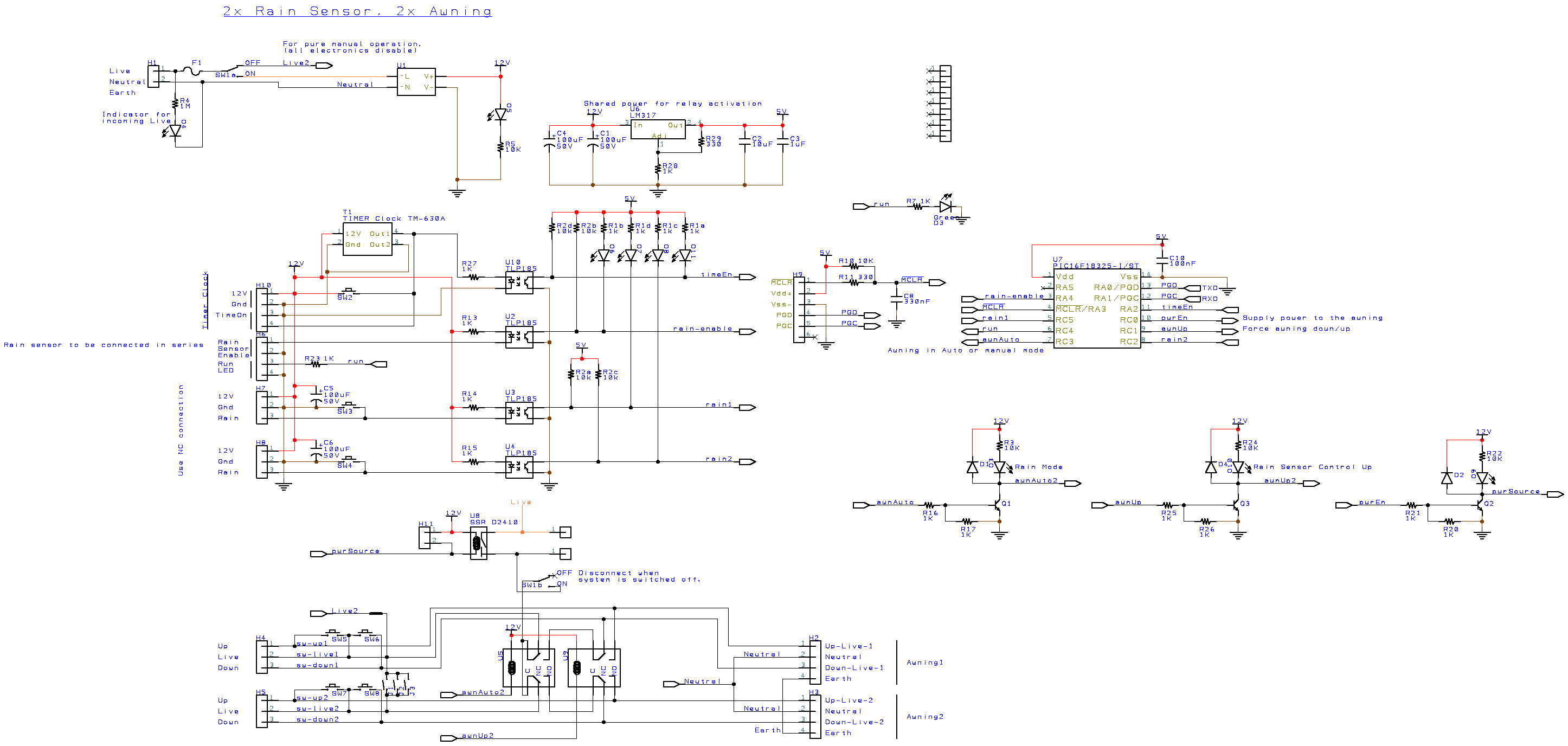
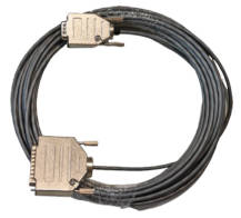
The process of custom cable assembly starts from client providing information of the custom cable project. Cable wiring connections various from project to project.
Our engineer will obtain the relevant information or documentation of the required cable. We will also understand the context of your cabling project to ensure that the connector and cable type that we select are suitable for your application.
Material Selection: Choosing the right materials is critical for ensuring durability and functionality. This includes selecting insulation, shielding, and jacketing materials that comply with industry standards.
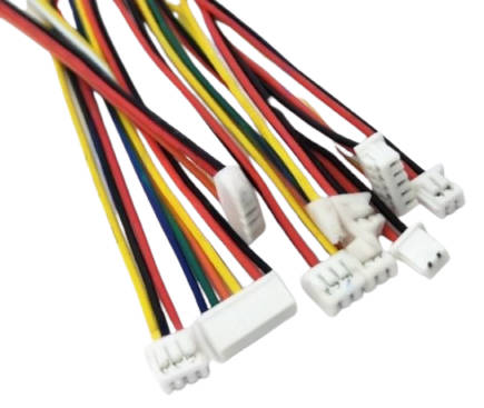
Connector Selection: The choice of connectors is crucial as they must be compatible with both the cable and the devices they will connect to. Proper selection enhances reliability and performance.
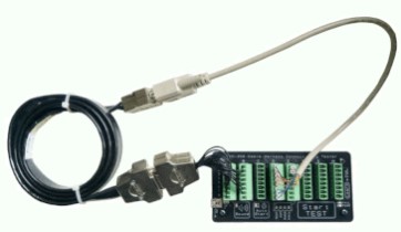
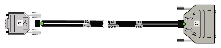
Manufacturing: Once designs are finalized, the manufacturing process begins. This includes cutting wires to precise lengths, stripping ends, and attaching connectors through soldering or crimping methods.
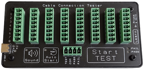
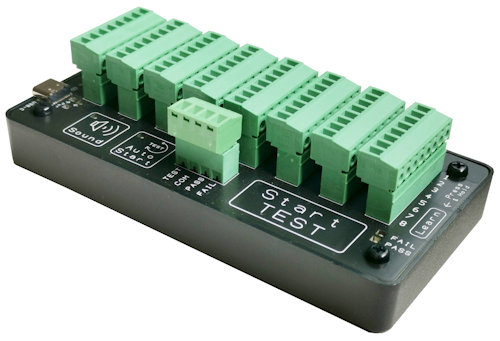
Testing: Each assembly undergoes thorough testing to verify its performance against specified standards. This may include electrical testing, environmental assessments, and functional tests.
Shipping: After passing all quality checks, the custom cables are packaged appropriately for delivery to clients.
Benefits of Custom Cable Assemblies
Custom cable assemblies provide several advantages over standard options:
Tailored Performance: Clients can specify exact requirements regarding materials and configurations, ensuring optimal performance for their unique applications.
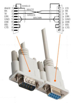
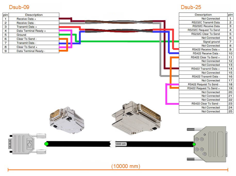
This is especially for specialised communication cable type like RS232, RS485, RS422, CAN bus, Profibus, etc…
Quality Assurance: The rigorous testing protocols associated with custom assemblies lead to higher quality control than off-the-shelf products.
Increased Efficiency: Custom assemblies can integrate multiple types of cables into a single solution, reducing clutter and minimizing potential damage from multiple connections.
Flexibility in Production: Manufacturers can produce exactly what is needed without excess inventory, allowing for better resource management.
Contact us for custom cable fabrication
Contact our engineer today for your custom cable wiring connection fabrication.