NFC (Near Field Communication), RFID
It is all about NFC technology applications, RFID tags, ISO/IEC14443, ISO/IEC18092. Information about near field communication RFID technologies.
- Edited by Lim Siong Boon, last dated 03-Mar-2012.
Topic Discussion Overview
|
|
Having the Right Mindset for RFID technology. RFID is known as Radio Frequency IDentification. The technology is able to wireless-ly picking up information from a RFID tag which can be embedded onto most object. Fast and reliable. RFID has helped to rise up our productivity. The process starts with the RFID reader transmitting power and command wireless-ly. The RFID tag intecept the energy to power up itself. It starts to decode the request commanded and transmit the result back to the RFID reader. All these happen instantly with microseconds.
Many of the old technologies (bar-code, magnetic stripe, smart card) can be replaced by RFID system, but rate of adoption rate is slow. Examples of applications that the RFID have completely taken over are, security door access system and transportation payment card. Comparing RFID over the old technologies, it is perceive to be more expensive. The technology do has its advantages and disadvantages, which is why not all applications use RFID. People likes to compare RFID to a bar-code system which is a cheaper alternative. The fact is, RFID tag will never be as cheap as a printed bar-code. It is more complex than bar-code. No matter how big the production volume will be, it will not be cheaper than the bar-code. Using a RFID to perform barcode application is analogy to hiring an engineer to do simple office cleaning work. No company would be in the right set of mind to invest in a expnsive solution to replace what a cheaper solution would solved. People also think of RFID technology as a solution. RFID unique and good, but it can only solve part of the problem that we are facing in our life. You can analogy it to a very good engineer that you have hired. He/she has all the skills and know-how to design a quality system that no one else can, but there are no proper tools and equipments provided. Only a broom and a dustpan is provided. The engineer will be as good as a cleaner. RFID is designed to solve certain problem very efficiently. By itself, it cannot do any much. It has to work hand in hand with another good technology. RFID has its own unique properties that no other technology is able replace it completely. Applying RFID technology to its advantage, to the right application will be the key to success adoption. If you want RFID system to be successful, you cannot think using a bar-code brain. This site is dedicated to understand more about the properties of RFID technology, hence allowing us to apply its unique leading edge where no other technologies can replace. The focus will be mainly in the RFID for ISO/IEC14443 (HF 13.56MHz RFID system) which has a near perfect characteristic for interaction between humans and object; and also information on ISO/IEC18092 (NFC protocol implementation) which is the new trend on applying RFID technology. With the growing number of NFC mobile phones being launch, we can clearly see that the industry is committed in making our life more productive. Let us start by a simple overview of various technologies that is related to RFID. We can easily see the advantages/disadvantages that the RFID can have in the application of tagging and identification.
|
||||||||||||||||||||||||||||||||||||||||||||||||||||||||||||||||||||||||||||||||||||||||||||||||||||||||||||||||||||||||||||||||||||||||||||||||||||||||||||||||||||||||||||||||||||||||||||||||||||||||||||||||||||||||||||||||||||||||
|
Comparison chart of tagging/identification technologies
Selecting guide your RFID technologies. Click here -> rfid-guide.pdf |
|||||||||||||||||||||||||||||||||||||||||||||||||||||||||||||||||||||||||||||||||||||||||||||||||||||||||||||||||||||||||||||||||||||||||||||||||||||||||||||||||||||||||||||||||||||||||||||||||||||||||||||||||||||||||||||||||||||||||


Click to enlarge the picture.
|
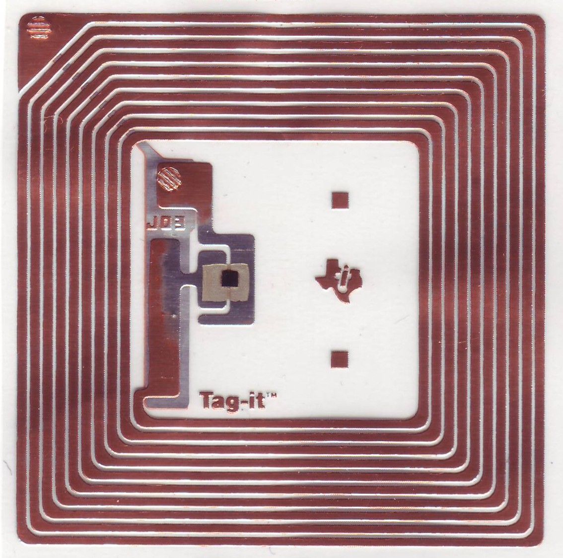
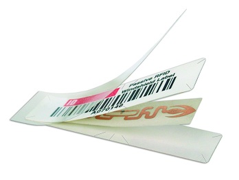
Basic RFID Tag RFID tag, is also known as RFID Transponders. The tag is make up of three basic components. An IC chip, an antenna or coil, and a substrate that holds the chip and antenna/coil together. The picture on the left shows two typical tag design. The one on the left is a coil design. It is mean for LF/HF RFID tag (low/high frequency) that operates in a low frequency range. The tag uses induction method as a means for power and communication. The UHF RFID tag (ultra high frequency) on the right uses a dipole antenna design. The tag uses RF transmission (radio frequency operating at a much higher frequency) method to obtain its power and achieve communication. Higher frequency tag is able to transmit information faster, and need less energy to receive/transmit information compare to a tag that uses lower frequency; lower frequency takes more time. Antenna helps to transmit the signal can be smaller at higher frequency. With the signal transmitting out of the antenna, tag can be read at a further distance away. At this stage in time, you may think that a UHF tag is better than a HF tag. You can be right and wrong. A tag that can be read at a far away distance can be good. The same property will not be good if you need to get hold of a specify tag but end up with all the rest of the tag nearby. There is little value in defining the good and bad. What is more important, is understanding the property of what it can or cannot do, and apply its properties to its advantage. This depends mainly on the application. For the application of tagging an object, I have valued HF tags more than the other alternative technologies. Passive RFID tag using HF or NFC has a higher potential in solving problems relating to interraction betweeen living things and physical object. This which will be further presented as another topic in another site.
|
|||||||||||||||||||||||||||||||||||||||||||||||||||||||||||||||||||||||||||||||||||||||||||||||||||||||||||||||||||||||||||||||||||||||||||||||||||||||||||||||||||||||||||||||||||||||||||||||||||||||||||||||||||||||||||||||||||||||||||||||||||||||||||||||||||||||||||||||||||||||||||
|
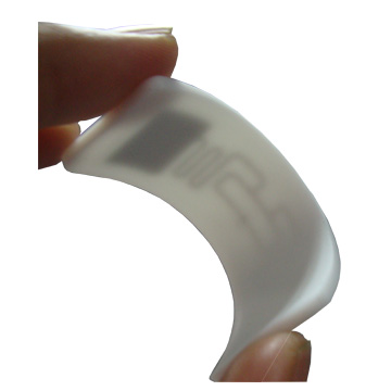
This is a finger that I have downloaded from the internet. Notice the black square dot on the middle of the finger. That is the RFID transponder IC chip which can be found on a RFID tag. You can hardly see it.
|
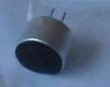
IC chip for RFID tag The IC chip on the RFID tag is very very small; not much bigger than a gain of sand (see photo on the left). This makes the tag small enough for a lot of purpose. This IC contains memory which can store information. The cost of the chip is proportional to the memory size and functional it has. The IC chip needs power to operate. It will get its power from its antenna. The tag’s antenna will capture the energy transmitted by the RFID reader. The RFID reader will generate the RF energy from its own antenna when a read command is initiated. There is a limit distance in which the antenna can effectively capture the RF energy for powering up the tag. This distance will depends on the transmitting power from the RFID reader, as well as the size of the tag’s coil. The bigger the coil on the tag, the further the distance. As a rule of thumb, a bigger tag is expected to achieve a further read distance than a smaller tag.. **pic of transmitting energy from induction stove, RFID reader. Coil with LED. big tag further distance. higher power further distance When the tag received enough power to operate, the IC will immediately power up, and response to the command from the RFID reader. The tag will usually read the binary information contains in its memory and send them back to the reader. The basic form of read information will be the tag identification number. If the tag contains additional user data, the reader can issue command to read them all. All these process happens within micro seconds. RFID tag is essentially similar to a memory card. Similar to the flash memory card that we have been using for our digital camera, the RFID tag is using wireless power/communication, and has much less memory. The memory available can be as little as a few bytes to store the tag ID, to about 8Kbyte to store other user’s data. Each alphabet letter takes about 1byte of space, so a 8Kbyte memory can store about 8000 characters. The higher memory capacity tag will usually cost a bit more. The LF RFID tags that I have seen can only be read. HF tags can be read/write. It is also possible to protect the tag from data writing. Some IC chip is able to kill the tag, therefore prevent a read from the tag, rendering the tag useless. Depending on the chip, tags can be pre-programmed during the manufacturing to contain the same or unique ID no. (identification number). An unique ID no. for each tags will enable the reader to differential the multiple tags read. LF and HF tags uses induction method and has a short reading distance <10cm. UHF tags can go as far as 10m. The distance will varies with varies RFID reader’s transmitting power and antenna/coil size. A bigger size antenna will usually have a longer read distance.
|
|||||||||||||||||||||||||||||||||||||||||||||||||||||||||||||||||||||||||||||||||||||||||||||||||||||||||||||||||||||||||||||||||||||||||||||||||||||||||||||||||||||||||||||||||||||||||||||||||||||||||||||||||||||||||||||||||||||||||||||||||||||||||||||||||||||||||||||||||||||||||||
|
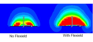
Fig 1. Magnetic field pattern of a
typical RFID operation.
|
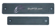
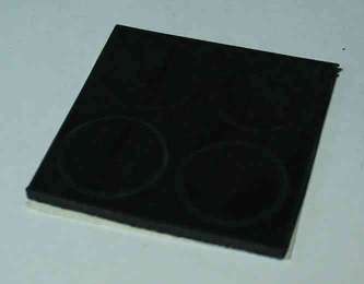
RFID operation with metalic or liquid objects RFID has difficulty operating near metalic, liquid object (water bottle/ human body). Induction field around the tags will be collapse by these object. A minimum gap away from such object is required for proper operation. Metal surface can block/reflect RF signal, causing distortion to the signal, making it difficult to read the tag. There are special anti-metal tags (RFID Metal Pad) that allows RFID to operate under such tough condition. These tags are padded with a sheet of ferrite material behind the tag. The sheet actually forms the gap between the tag and the metal surface, allowing the tag to be read through the RF. The ferrite is itself a RF friendly material which permits the RF & field to sustain. With this padding, the tag readability can be improve slightly.
Ferrite sheet is available from: |
|||||||||||||||||||||||||||||||||||||||||||||||||||||||||||||||||||||||||||||||||||||||||||||||||||||||||||||||||||||||||||||||||||||||||||||||||||||||||||||||||||||||||||||||||||||||||||||||||||||||||||||||||||||||||||||||||||||||||||||||||||||||||||||||||||||||||||||||||||||||||||
|
|
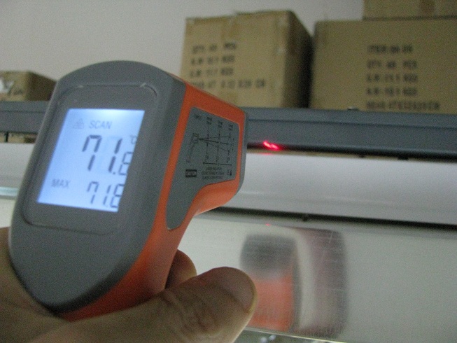
Active RFID tag with built-in sensor Active RFID tag (sef powered, usually a battery) operates like a typically electronic transceiver device. Reading distance is a lot further than a passive RFID tag (not self power). The operations is similar to a passive tag where the reader will be able to retrieve the tag information when it is near enough. Some call the tag a signal beacon, where the tag keeps sending signal out. The tag can be read at a much further distance. This is because it has its own power source and do not need to harvest from the reader. There are active tags that have built in sensor. The temperature/humidity sensor for example, will be operated by the RFID tag and send back the temperature read back to the reader. The battery usually last quite sometime, but it will definately need replacement one day. |
|||||||||||||||||||||||||||||||||||||||||||||||||||||||||||||||||||||||||||||||||||||||||||||||||||||||||||||||||||||||||||||||||||||||||||||||||||||||||||||||||||||||||||||||||||||||||||||||||||||||||||||||||||||||||||||||||||||||||||||||||||||||||||||||||||||||||||||||||||||||||||
|
Buy your NFC Tag Now at the PIC-store
Three typical standard among RFID tags
Good RFID tag reference information, http://www.gorferay.com |
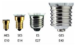
RFID tag IC chip and standard When dealing with RFID tags or reader, we will often come across various ISO standards. These ISO defines a common standard for the hardware or software to interact with one another. The LF RFID (125Khz), ISO11784/ISO11785 is a common standard. For UHF RFID, it is EPC Gen2 or EPCglobal UHF Class 1 Generation 2 For HF there are standard ISO15693, ISO14443 and ISO18092 (NFC). For NFC, we will focus on ISO14443 and ISO18092.
In transport applications, cards suffer from daily use, for which reason contactless cards are preferred. Contact cards are more prone to hardware wear-out, hence contactless cards are better suited in the transport sector. This led to the creation of the RFID standard, ISO 14443, composed of 4 parts. It operates in the non-licensed 13.56 Mhz band. As there were two main “competitors”, there are two substandards:
Later under impetus from Sony, the NFC standard was established as ISO 18092. It’s a backward compatible extension to RFID, mainly aiming at use in mobile phones. It’s was actually proposed as ISO 14443 type C by Sony, based on FeliCa. It’s used e.g. in the Hong Kong Octopus and Singapore EZ-link systems. It did not make it to the 14443 standard, but came back as NFC. Article for ISO/IEC 14443
Mifare Tag ID issues (tag ID unqiue?) Mifare name comes from the “MIkron FARE Collection System”. Mikron was aquired by Philips (NXP) in 1998. Given the Mifare Classic tag ID of 4 bytes, will the tag ID run out of unique ID?
RFID tag/transponder IC manufacturer
|


 Active RFID tag
 Active RFID tag with sensor attached
| 3. Tag Packaging |
Common RFID tag packaging
**Packaging (find chinese terms) Reference:
|
|||||||||||
|
|
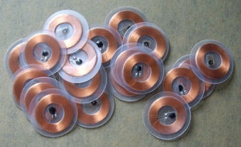
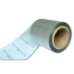
Inlay (dry) Dry inlay is the fundenmental building block for RFID tag. They are usually be further packaged into RFID tag products. The term “dry” means that it does not have adhesive on it’s tag surface. The inlay can comes in roll or sheet form.
Common size:
|
|||||||||||
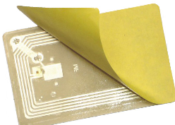 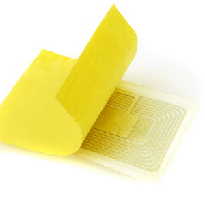  |
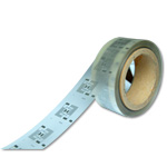
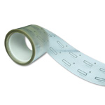
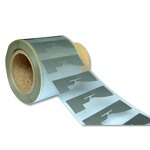
Inlay (wet) Wet inlay means that the inlay has adhesive on one of its side. The tag will be attached to a pressure sensitive liner base. – sticker label
|
|||||||||||
|
|
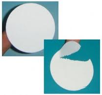
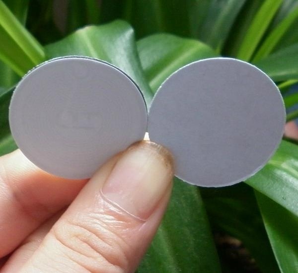
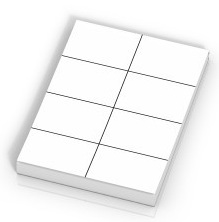
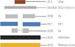
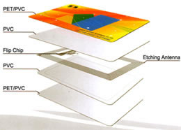
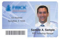
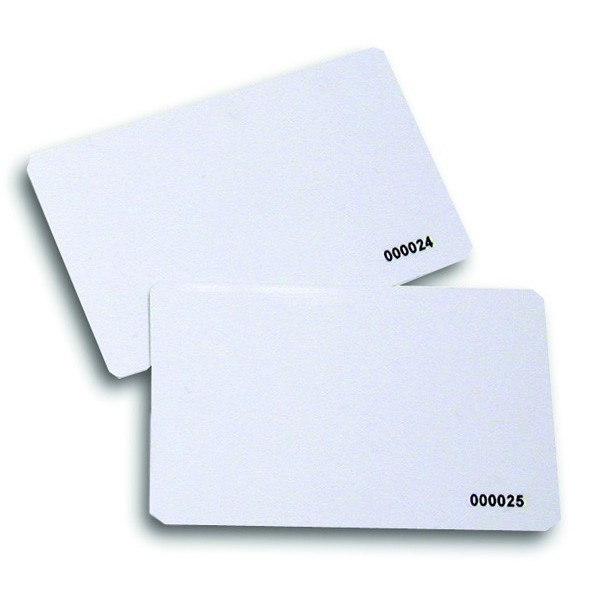
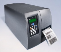
IDCard/Badge These are hard PVC card about 1mm thickness. The card printing can be customised. There is also a special printer that prints on these plain tags. –
PVC/Plastic card
|
|||||||||||
|
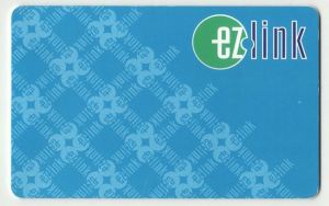
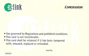
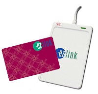
ezlink using CEPAS card
|
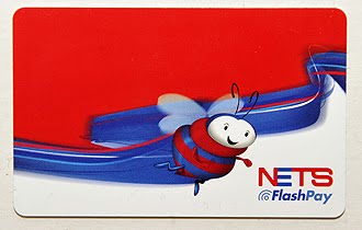
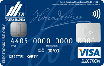
Payment Card (Singapore) Ezlink, based on the Sony FeliCa smartcard technology Flash Pay payWave CEPAS = ISO/IEC 14443-4 + ISO/IEC 7816-4: 2005
– Singapore Standard, specification for contactless e-purse application
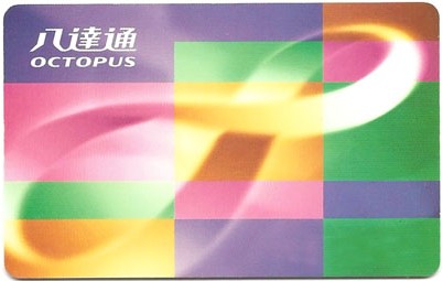
Octopus card, based on the Sony FeliCa smartcard technology base on MIFARE DESFire EV1 card |
|||||||||||
 |
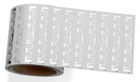
Label Stickers | |||||||||||
    |
Key Chain, Key Fob | |||||||||||
    |
Waterproof Rubber Bracelet, Wrist band | |||||||||||
   |
Patient Tag | |||||||||||
  |
Lugagge Tag | |||||||||||
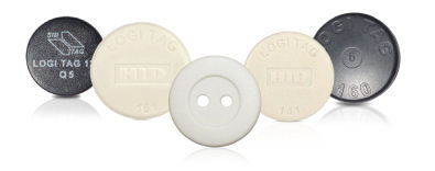  |
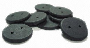
Button Tag, Washing Tag | |||||||||||
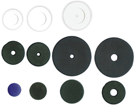   |
Disc or Ring Tag, Laundry Tag, Pucks | |||||||||||
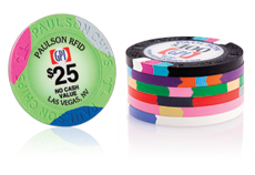 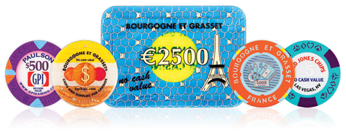  |
Casino Game Token | |||||||||||
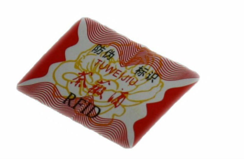  |
Fragile Tag, Security Tag | |||||||||||
  |
Anti-Metal Tag | |||||||||||
  |
Hard Tag | |||||||||||
 |
Pill | |||||||||||
   |
CD label | |||||||||||
|
|
UHF tags | |||||||||||
|
RFID Tag manufacturer
|
|


|
|
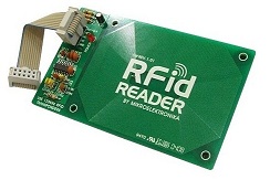
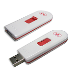
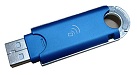
RFID reader is getting more and more common. Nowsaday Windows & mobile phone OS has built in driver treating RFID reader as a standard device. Common RFID interfaceRS232 RS485 Wiegand USB Ethernet |
|||||||||||
|
|
USB RFID reader kit |
|||||||||||
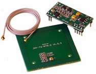  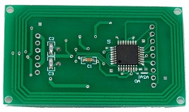 |
OEM board | |||||||||||
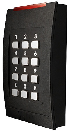 |
Door Access Security | |||||||||||
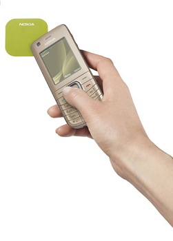  |
Mobile phone NFC / RFID reader | |||||||||||
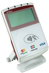 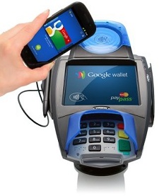 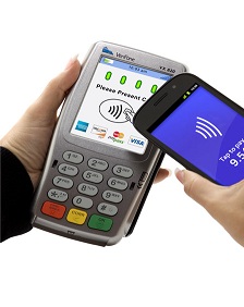 |
Payment station | |||||||||||
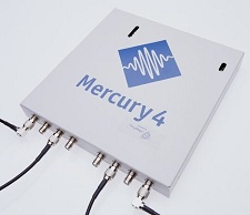 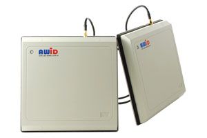 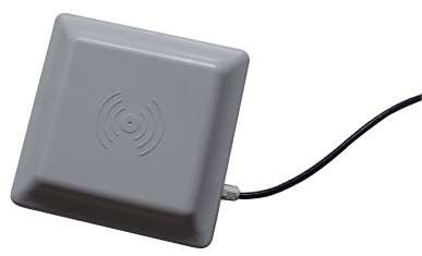 |
UHF RFID reader and Antenna | |||||||||||
|
RFID Reader manufacturer
|

|
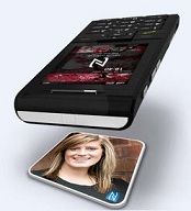
NFC phone to phone, Phone to RFID tag
NFC currently use for Payment, transportation payment. Instantly access to webpage, Instant bluetooth/WiFi connectivity. |
Reference: – NFC Tags A technical introduction, applications and products, R_10014 – Understanding the Requirements of ISO IEC 14443 – MIFARE Ultralight as Type 2 Tag, AN1303 – NFC Type MIFARE Classic Tag Operation, AN1304 |
|
13.56MHz RFID card reader IC
|
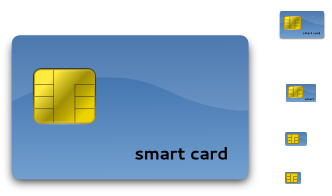
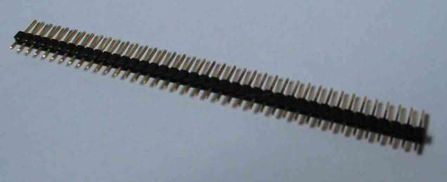
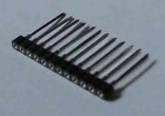
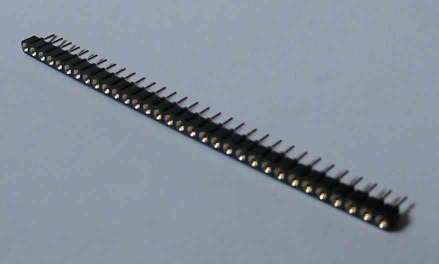
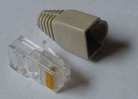
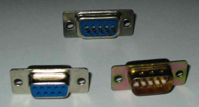
Getting to understand RFID was quite a confussing experience, with so many technical jargon. This was the reason why this website is setup; to sort out all the technical stuff into bits and pieces. Card Reader is another interest topic to looking. A card reader helps to read out the information in a tag. An RFID reader is not a different device to understand, but not the card reader. What is the difference between an RFID reader and a card reader? The RFID reader reads RFID tag. There are many variety of RFID standards in the industry. This means that there are also many type of RFID reader to read each type of card. (The type of cards was already presented above). The variety of reader is going to make things complicated for developer who are developing application. This call for an universal solution known as ISO 7816. This is a standard defined for interfacing application with all smart card devices. From what I read in the internet, this standard goes way back to the smart card technology. The smart card unlike RFID card is using wired communication to read the information on the card. You can identify it by the contact pins as shown in the following pic.
It is possible that a card has both the smart card as well as RFID card. With the introduction of new form of card like RFID, the ISO 7816 evolve over time. ISO 7816 defines a standard interface for the card reader. The communication standard to a card reader device becomes a standard. Article for ISO 7816 (specification for interfacing with card reader) – AN4029, The DS8007 and Smart Card Interface Fundamentals
PCSC Personal Computer Smart Card is a standard framework for Smart Card access on Windows Platforms. This will make the job easier for application developers to interface to a card reader. To the developer, all card reader seems to work the same way. The window operating system will automatically detects. Interoperability Specification for ICCs and Personal Computer Systems – PCSC_Part1,
Introduction and Architecture Overview.pdf.pdf
|
|||||||||||||||||||||||||||||||||||||||||||||
|
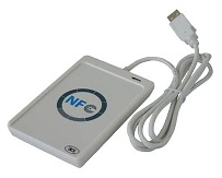
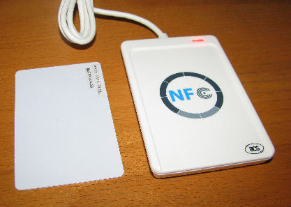
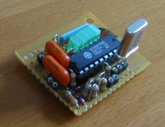
My card reader ACR122 NFC card reader from ACS. Documentation |
This is the first NFC card reader that I have brought. I have purchased this reader without any development kit, and was struck wondering how I can read a RFID tag without any software. After understand about ISO 7816 and PCSC, I managed to find a number of free software that can communication with this NFC card reader. They are designed to work with PCSC compliants card reader. – SCardToolSet,
Smart Card ToolSet PRO v3.4 The software are able to detect my card reader immediately. When my RFID tagis placed on the reader, the software detects it and display the tag information. The very first unqiue string that was captured when I read the RFID tag is this string call ATR (Answer To Reset). It is a very weird name, because I was thinking that this should be the unqiue ID of the RFID tag. No it is not. This ATR string (as defined in ISO 7816) is telling us how we can communicate with the current tag found on the card reader. This is the ATR string that I read when the tag (picture on the left) is on the reader ATR = 3B 8F 80 01 80 4F 0C A0 00 00 03 06 03 00 03 00 00 00 00 68 So what does this hexidecimal string of number means?
With this ATR string provided by my card reader, I will know more about the RFID tag that I am actually dealing with. The RFID tag that I have place is using the Mifare Ultralight tag’s IC chip. ISO14443A is use for communication between the reader and the tag. The rest of the information seems not so useful to me.
To communicate with the card reader we will have to send a string of bytes to the card reader. The data format to communicate with the reader is known as APDU (Application Protocol Data Unit). I have refered to the API (Application Programming Interface) datasheet provided by the card reader manufacturer. The first command to try is the command “Get Data”. The command will fetch the unique ID of the tag. data send -> FF CA 00 00 04 The following response bytes are received. data received <- 04 06 CD E2 90 00
Next I tried to get the card reader firmware version. data send -> FF 00 48 00 00 The data received is “ACR122U210” in ascii format
|
|||||||||||||||||||||||||||||||||||||||||||||
| Reading Mifare Ultralight tag 1, tag ID |
Another Mifare Ultralight tag1 was read for its ATR and tag ID ATR
= 3B 8F 80 01 80 4F 0C A0 00 00 03 06 03 00 03 00 00 00 00 68
|
|||||||||||||||||||||||||||||||||||||||||||||
| Reading Mifare Ultralight tag 2, tag ID |
Another Mifare Ultralight tag2 was read for its ATR and tag ID ATR
= 3B 8F 80 01 80 4F 0C A0 00 00 03 06 03 00 03 00 00 00 00 68
|
|||||||||||||||||||||||||||||||||||||||||||||
|
Reading Singapore Ezlink card (CEPAS card)
|
Next I tried another RFID tag. Our Singapore Ezlink card, which stores transportation logs in CEPAS format. ATR = 3B 8C 80 01 50 72 23 AA 5E 1C 2D 94 11 F7 71 85 4F When the tag is removed and placed on the reader again, the ATR string changes. This is unlike the previous tag where the ATR will remains the same for the same tag. ATR
= 3B 8C 80 01 50 21 0A 96 CF 1C 2D 94 11 F7 71 85 98 The ATR tells us that it uses the application identifier 0x50. I don’t know what it means.
Next I proceed to send read tag ID command. ATR
= 3B 8C 80 01 50 5D 83 48 22 1C 2D 94 11 F7 71 85 5E ATR
= 3B 8C 80 01 50 FE 15 0F A4 1C 2D 94 11 F7 71 85 AA The tag ID changes with the ATR string. A closer look review that the tag ID is the same data as the substring in the ATR.
|
|||||||||||||||||||||||||||||||||||||||||||||
| Reading DESFire EV1 2K tag |
A DESFire EV1 card ATR string is unexpectedly short. ATR = 3B 81 80 01 80 80 The ATR string remains the same when the tag is APDU send -> 90 0A 00 00 01 00 00 APDU send -> 90 0A 00 00 01 00 00 APDU send -> 90 0A 00 00 01 00 00 APDU send -> 90 0A 00 00 01 00 00 APDU send
-> 90 0A 00 00 01 00 00 APDU send -> 90 0A 00 00 01 00 00 APDU send
-> 90 0A 00 00 01 00 00 APDU send -> 90 0A 00 00 01 00 00 APDU send
-> 90 0A 00 00 01 00 00 APDU send -> 90 0A 00 00 01 00 00 |
|||||||||||||||||||||||||||||||||||||||||||||
| Loading a key to Mifare Ultralight |
Load
|
|||||||||||||||||||||||||||||||||||||||||||||
| Reading Mifare Ultralight memory (64 bytes) |
Read binary Page 0x04, 4 bytes Read binary Page 0x04, 16 bytes Read binary Page 0x00, 256 bytes Read binary Page 0x01, 256 bytes Read binary Page 0x00, 16 bytes Read binary Page 0x01, 16 bytes Read binary Page 0x04, 16 bytes Read binary Page 0x08, 16 bytes Read binary Page 0x0C, 16 bytes Read binary Page 0x10, 16 bytes Read binary Page 0x10, 1 bytes Read binary Page 0x0F, 1 bytes Read binary Page 0x0F, 16 bytes Mifare tag memory data from page 0x01 to 0x0F read: 04 06 CD 47 E2 87 28 81 CC 48
00 00 00 00 00 00 Total memory is 64 bytes. Ascii message contains “1909–SIONG BOON LIM” This tag is a Mifare Ultralight tag with memory of 64 bytes byte 00 SN0 (serial number) Reading the tag ID full 7 byte serial number Actual Tag ID is in the following sequence (high address, high
byte), Try read tag ID 8 byte, not a correct
read |
|||||||||||||||||||||||||||||||||||||||||||||
| Reading Mifare Ultralight C memory (168 bytes) |
Read binary Page 0x29, 4 bytes Read binary Page 0x2A, 4 bytes Total available page is 42 from 0x00 to 0x29. |
|||||||||||||||||||||||||||||||||||||||||||||
| Reading Mifare Ultralight C memory (176 bytes) |
Read binary Page 0x2B, 4 bytes Read binary Page 0x2C, 4 bytes Total available page is 44 from 0x00 to 0x2B. |
|||||||||||||||||||||||||||||||||||||||||||||
| Reading Mifare 1K memory, part 1 |
Reading tag ID APDU send -> FF CA 00 00 07 (read
full tag ID, 7 bytes) APDU send -> FF CA 00 00 08 (try read
incorrect tag ID length) Read from block 0x04, 16ytes Authentication with a type A (0x60), key number 0x00 for memmory block 0x04 Read from block 0x04, 16ytes Read from block 0x04, 16ytes Card is removed and place back on the
reader. |
|||||||||||||||||||||||||||||||||||||||||||||
| Reading Mifare 1K memory, part 2 |
Authentication with a type A (0x60), key number 0x00 for memmory block 0x04 Read from block 0x04, 16ytes Read from block 0x05, 16ytes Read from block 0x06, 16ytes Read from block 0x07, 16ytes Read from block 0x08, 16ytes Read from block 0x03, 16ytes Authentication on block 0x04 can only allows reading of data for block 0x04 to 0x07 (which is on the same sector 1) for as many times without the tag leaving the card reader. Memory block 0x03, 0x08 cannot be read. Mifare 1K tag memory block
|
|||||||||||||||||||||||||||||||||||||||||||||
| Reading Mifare 1K memory, part 3 |
Authentication with a type A (0x60), key number 0x00 for memmory block 0x3F Read from block 0x3F, 16ytes Authentication with a type A
(0x60), key number 0x00 for memmory block
0x40 |
|||||||||||||||||||||||||||||||||||||||||||||
| Reading Mifare 4K memory |
Reading Mifare 4K is the same as Mifare 1K. Only the memory map is different.
|
|||||||||||||||||||||||||||||||||||||||||||||
| Writing Mifare Ultralight | Writing
to block 0x04 with 4 bytes of data 00 01
02 03 APDU send -> FF D6 00 04 04 00 01 02 03 APDU received <- ?? ?? |
|||||||||||||||||||||||||||||||||||||||||||||
| Reading Mifare Ultralight tag 1, containing NFC data |
Read binary Page 0x00, 16 bytes Read binary Page 0x04, 16 bytes Read binary Page 0x08, 16 bytes Read binary Page 0x0C, 16 bytes Read binary Page 0x10, 16 bytes Data Memory in the tag Seems like no NFC data inside. |
Abbreviations
| AID | Application ID |
| APDU | Application Protocol Data Unit |
| ATR | Answer to Reset |
| ATS |
Answer to Select |
| AFI | Application Family Identifier |
| CBC |
Cipher Block Chaining |
| CID | Card Identifier (logical card address, ISO 14443-4) |
| DES |
Data Encryption Standard, for more details about DES refer to [3]. |
| DSFID | Data storage format identifier |
| EDC |
Error Detection Code |
| EGT | Extra Guard Time |
| EOF |
End of Frame |
| ETU | Elementary time unit |
| KTT | Key Transfer Transponder |
| NAD | Node Address (ISO 14443-4) |
| NDEF | NFC Data Exchange Format |
| OSI | Open System Interconnection |
| OTP | One time programmable |
| PCB | Protocol Control Byte (ISO 14443-4) |
| PCON | Protocol Configuration byte of the reader |
| PPS | Protocol and Parameter Selection |
| RATS |
Request for Answer to Select |
| R-block | Receive ready block |
| REQA | Request ISO Type A |
| REQB | Request ISO Type B |
| S-block | Supervisory block |
| SID | Station ID |
| SFGT | Guard time after RATS |
| SN | Serial Number of a tag (a 32 bit number) |
| SOF | Start of frame |
| TDES | Triple DES |
| Value block | 32 bit data block format. Used in ticketing application |
**Tag making video (or machine)
Reference:
Keyword: NFC (near field communication), RFID (radio frequency
identification), RFID Reader/Writer, Internet of Things, Productivity


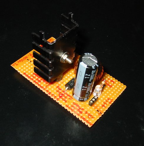
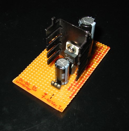
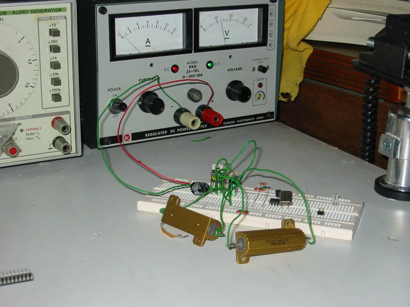
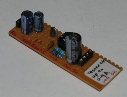
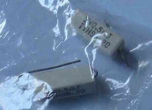
 Sample of
the 5Ω 50W aluminum house resistor used for testing 1A current
performance.
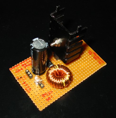
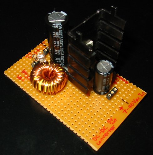
Sample of
the 5Ω 50W aluminum house resistor used for testing 1A current
performance.
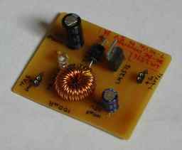
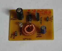
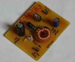
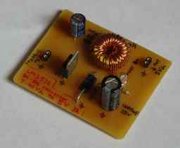
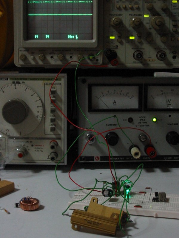
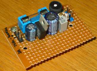
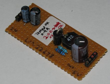
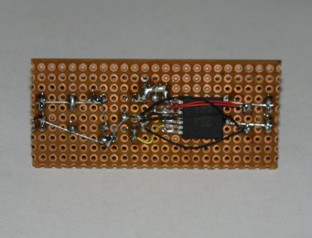
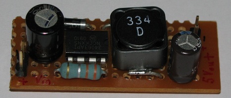
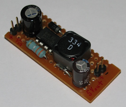

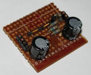
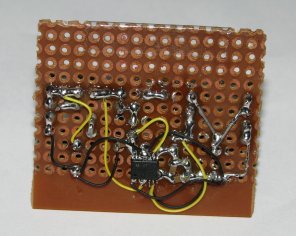
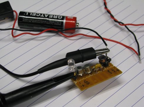
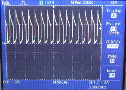
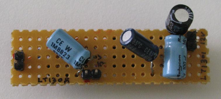
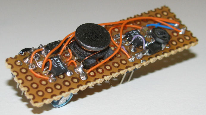
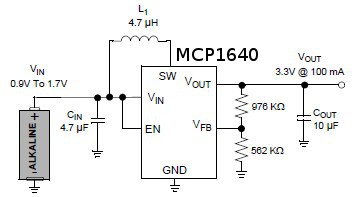 Output 3.3V from a 1.2V alkaline battery using MCP1640
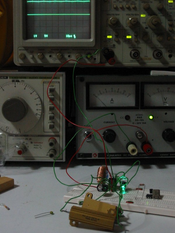
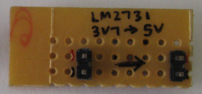
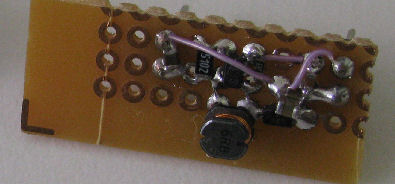
 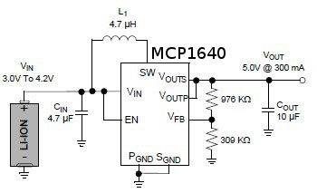 Output 5.0V from a 3.2V LI-ION battery using MCP1640


 available from
  available from
  available from
  available from
 no button
press
no button
press ‘1’ press
and hold
‘1’ press
and hold release
from button ‘1’
release
from button ‘1’ ‘2’ press
and hold
‘2’ press
and hold release
from button ‘2’
release
from button ‘2’ ‘0’ press
and hold
‘0’ press
and hold


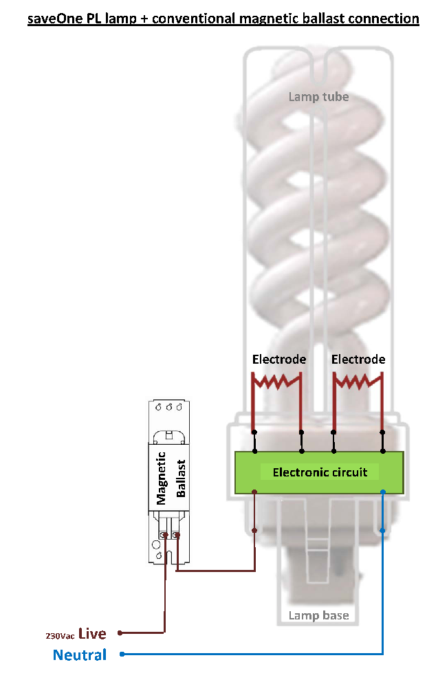
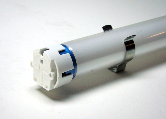
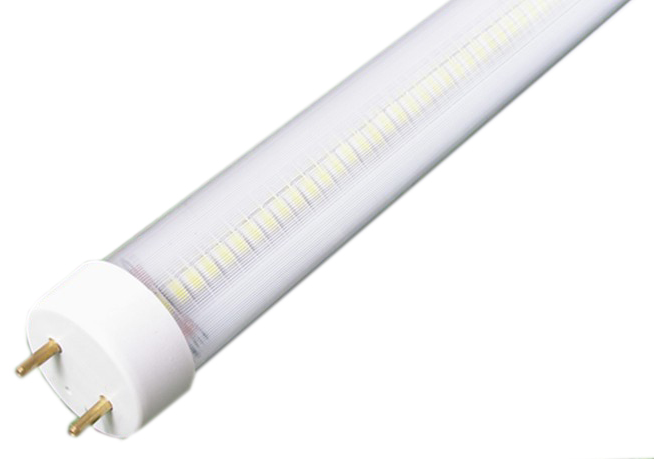
 and a fluorescent tube
  to work.


