nRF52840-DK BLE Bluetooth Development Kit Tutorial Start-up Guide

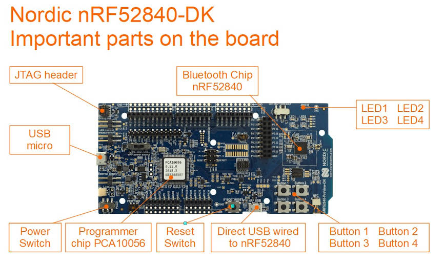
nRF52840-DK is a development kit for nRF52840 SoC (System on Chip) chip. Mainly design for Bluetooth application, supporting Bluetooth 5.0, Bluetooth Low Energy (BLE, Bluetooth 4.0).

Check out this video introduction of this nRF52840-DK development kit board.

Preparation

What do you need?

  • Download Apps “nRF Toolbox for BLE” for Andriod or IOS
    Demonstrate Bluetooth profile, and support Nordic UART and DFU
  • Download Apps “nRF Connect” for Andriod or IOS
    For scanning and exploring Bluetooth Low Energy devices and communicate with them.
    Support DFU and Eddystone.
  • Download Apps “nRF BLE Joiner” for Andriod or IOS
    Proprietary method to convert Bluetooth into network devices (IPv6 nodes).
  • Download demo firmware from the Nordic website.
    https://www.nordicsemi.com/Software-and-tools/Development-Kits/nRF52840-DK/Download#infotabs
    In this example, we download the “Proximity demo
    Unzip “proximity_demo.zip”
    get ready the hex file “ble_app_proximity_s132_pca10040.hex”
    Inside the zip file contains readme.txt file to explain how this demo works
  • XXX -> Download Apps “nRF UART 2.0” for Andriod or IOS

Ways to program Nordic nRF52840 chip on the nRF52840-DK

Reference: https://devzone.nordicsemi.com/nordic/short-range-guides/b/getting-started/posts/nrf52840-dongle-programming-tutorial
https://devzone.nordicsemi.com/f/nordic-q-a/37219/how-to-upload-the-application-hex-file-uisng-usb-drag-n-drop-on-nrf52840

  • Programming the nRF52840 chip, through the USB Mass Storage, vs SWD (Left side of the board)
  • Programming the nRF52840 chip, through the nRF USB, vs serial USB bootloader (Bottom side of the board)

First Thing First

Download the latest SDK project files from nRF5 SDK product website. .
https://www.nordicsemi.com/eng/Products/Bluetooth-low-energy/nRF5-SDK#Downloads

The nRF5 SDK zip files contains many example projects for your to try and test.

Here is a pre-downloaded copy of nRF5 SDK ver 16.0.0 (nRF5SDK160098a08e2.zip, file size about 153MB)
in case you are having issue downloading from the official website.

Method 1 to program nRF52840 development kit via USB Storage Drive

To help you get start, to be in control of the nRF52840-DK board, I have this simple guide here to help you load in the hex file onto your nRF52840-DK board, to build up your confident.

Hex file the machine codes for the nRF52840 microcontroller chip after compiled from the source code. Nordic SDK contains both the project source code as well as the compiled *.hex file.

Here is a simplest way to test if the hex file is successfully loaded (or programmed) into the nRF52840-DK development kit.

1) Download the following files,

These 2 *.hex files are LED demonstration example which is found in the nRF5 SDK zip file that you downloaded eariler. Under the directory “examples\peripheral\blinky\hex\” & “examples\peripheral\led_softblink\hex\”. The source code can also be found in the project directory.

Please take note that there are project folder for different type of development board. One is for pca10040 development kit board, and the other is pca10056 development kit board. The one I have is PCA10056. You can take a look at the white sticker which is paste on top of your nRF52840-DK board to confirm which board you have. If you choose the wrong *.hex file, the example will not work. The files has a prefixed name “_pca10056.hex” at the back.

List of board types

PCA10040
PCA10056
PCA10059

2) Connect up your nRF52840 board with a micro USB cable.

You should be able to see a storage drive popping out from your computer. Inside this drive “JLINK”, you will see the following files inside.

  • MBED.HTM
  • README.TXT
  • Segger.html
  • User Guide.html

3) Copy the “blinky_pca10056.hex” hex file into the root of the JLINK drive.
This copy action will trigger a programming process of the hex file into the nRF52840 chip.
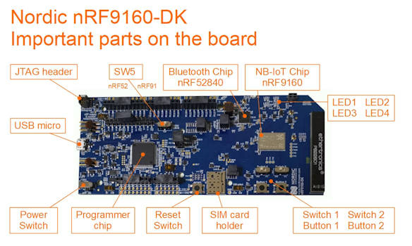
After a short second, you should see the LED1 LED2 LED3 LED4 on the nRF52840 board started to lights on in sequence, followed by lights off in sequence.

4) Next, copy the “led_softblink_pca10056.hex” hex file into the root of the JLINK drive.
After a second, you should see that the 4 LED now behaves differently. They will now fade out and fade on the lights. The old hex file can be remains in the drive. The programming action will only take place during the first time transferring of the *.hex file onto the JLINK drive.

That’s all for a simple demonstration of programming the nRF52840 chip that is on the nRF52840-DK development kit board. Simple just load in the hex file to nRF52840-DK board.

You have successfully programmed the nRF52840 chip.

Method 2 to program nRF52840 development kit via SEGGER Embedded Studio Software

1) Install and open the SEGGER Embedded Studio. If you are facing issue with the installation, you may like to visit this page for some SEGGER installation experience.

2) Open source code projects. We will use the project “blinky_pca10056”

From the menu bar go to File -> Open Solution

Open solution is like open project in other development platform. Go to the nRF5 SDK directory and select the project file “examples\peripheral\blinky\pca10056\blank\ses\blinky_pca10056.emProject“.

Folder “ses\” for the project files using SEGGER Embedded Studio.
Folder “armgcc\” is for the project files using GNU Arm Embedded Toolchain.

The project will be loaded.

In this project, you will see the file “main.c” where the blinky action codes is. Play around by modifying the code. This “main.c” file is share by other projects (defined by different board)

3) Program your new code to the nRF52840-DK board.

Ensure that you board is connect via the USB micro.

From the menu bar go to Build -> Build and Run (Ctrl+T or Ctrl+F5)

The SEGGER software will compile your code and load it to the nRF52840-DK board. It will take quite a couple of seconds to complete the up loading.

This completes your experience loading your codes using SEGGER Embedded Studio.

Play around with the other projects to get yourself familiar with the other peripherals on the chip nRF52840. Learning digital I/O pins and UART pins are the most important to help you get started in your microcontroller firmware programming. Once these two peripheral are mastered, understanding the rest will be much simpler.

For C++ coding reference, please click here to refer to this reference page.

Method 3 to program nRF52840 development kit via nRF Connect Programmer software

Check out this page.
https://www.pic-control.com/nordic-chip-programming/

Method 4 using nRF52840-DK as a programmer to program other boards

The nRF52840-DK can be used as a programmer to program other external board using the P19 Debug Header or the P20 Header Pins on the board. The DK board will detect the VTG pins for any board connected to it. If there is a connecting board, the nRF52840-DK will program the external board instead of the nRF52840 chip onboard the nRF52840-DK board.

The pins required for the programming are,

Programmer Pins
(Serial Wire Debug pins)
nRF52840nRF52832nRF51822
VTG (input to detect voltage), (short to Vdd)
SWD IOAC24Pin 26Pin 23
SWD CLKAA24Pin 25Pin 24
Gnd Detect (detect ground)

You can use ST-Link programmer to program the nRF52840 chip directly.
https://www.youtube.com/watch?v=_-d2d6Vc3lg

nRF52840-DK can act as a programmer. This programmer is J-Link compatible and can work with SEGGER software tool.

ST-Link and J-Link is not the same, but both can be use to program the chip nRF52840

Method 5 programming using a JLink Programmer

The method of programming using a Jlink Programmer is similar to the previous example of programming using nRF52840-DK as a programmer. Programming is done via the debugging header.

You can use the following JLink programmer.

  • J-LINK EDU MINI (low cost)
  • SEGGER J-Link EDU
  • SEGGER J-Link PLUS (expensive)

Method 6 programming using the nRF Command Line Tools (nrfjprog)

Download and install nRF Command Line Tools “nrfjprog“. This program help loads the compiled firmware (*.hex) into the chip. This nRF Command Line Tools can be downloaded from Nordic website and install onto your computer.

Two things to take note before using this nrfjprog.

  • Setup environment for nrfjprog.
  • Ensure that the SDK points to the correct nrfjprog directory (version).

Add path to the environment variable of Win10, so that the program “nrfjprog.exe” can be accessible from any file directory. It is found in the following directory after installation.

C:\Program Files (x86)\Nordic Semiconductor\nrf-command-line-tools\bin

Ensure that the text file “Makefile.posix” in the SDK directory
F:\…..\nRF5 SDK\components\toolchain\gcc
is configured to point to the correct compiler’s install directory and version.

Begin

I am using the nRF52840-DK board (PCA10056), so we go to the following blinky project folder.
“…\nRF5 SDK\examples\peripheral\blinky\pca10056\blank\armgcc”

Inside the folder, it contains a “Makefile”. The make file contains the excuting of the program nrfjprog in sequence to load the compiled source code “*.hex” into the chip.

To flash the chip: (load *.hex into the chip)

//to program the nRF52 microcontroller chip with the hex file.
nrfjprog --family nrf52 --program $(OUTPUT_DIRECTORY)/nrf52840_xxaa.hex --sectorerase

//--> Please note that the microcontroller needs to be reset in order for the new firmware to run !!!
//Learning Notes:
//   flag --sectorerase     //to erase the memory sector (before the programming) where the code is flash onto.
//   flag --sectoranduicrerase     //to erase the memory sector (before the programming) where the code is flash onto.
//   flag --chiperase       //to erase all the user memory (before the programming) including UICR.
//reference: https://infocenter.nordicsemi.com/index.jsp?topic=%2Fug_nrf5x_cltools%2FUG%2Fcltools%2Fnrf5x_nrfjprogexe_reference.html

//verify the loaded firmware
nrfjprog --family NRF52 --verify nrf52840_xxaa.hex

//to reset the microcontroller chip after the programming
nrfjprog --family nrf52 --reset


//Example of programming a blinky firmware (LED indicator blinking firmware example)
> nrfjprog -f nrf52 --program blinky_pca10056.hex --sectorerase
Parsing hex file.
Erasing page at address 0x0.
Applying system reset.
Checking that the area to write is not protected.
Programming device.

//Example of verifying the firmware code flash in
> nrfjprog --family NRF52 --verify blinky_pca10056.hex
Parsing hex file.
Verifying programming.
Verified OK.

>>Example of flashing and verifying at one go
> nrfjprog --family nrf52 --program blinky_pca10056.hex --sectorerase --verify
Parsing hex file.
Erasing page at address 0x0.
Applying system reset.
Checking that the area to write is not protected.
Programming device.
Verifying programming.
Verified OK.

>>Example of flashing and verifying at one go, including a reset at the end.
> nrfjprog --family nrf52 --program blinky_pca10056.hex --sectorerase --verify --reset

To erase the chip:

nrfjprog -f nrf52 --eraseall

To execute this command is chip is hang.:

nrfjprog -f UNKNOWN --eraseall

Tip#: Using Win10 file explorer, you can simply key in “cmd” in the directory text field, the command prompt will be loaded with the path at the current window’s directory that you are at. Very convenient feature.

Nice video talking about make & cmake.
https://www.youtube.com/watch?v=fOtPq0PkqlE&feature=youtu.be

SDK configuration header file

In every project (solution), in the “Application” folder contains a file named “sdk_config.h” to allow you to configure some of the parameter of the project. To allow you to enable/disable software module in the project.

You can actually use a tool “CMSIS Configuration Wizard” in the SEGGER Embedded Studio to assist you in setting up an apps to assist you to do the configuration with ease.
https://infocenter.nordicsemi.com/index.jsp?topic=%2Fcom.nordic.infocenter.sdk5.v14.1.0%2Fsdk_config.html

First you have to go to File->Open Studio Folder…->External Tools Configuration.
You will need to paste some XML codes to enable the CMSIS tool.
Save the XML file. Close the SEGGER IDE and restart again.

This time round, go to the project application folder to look for the “sdk_config.h” file.
Right click it, you will now get to see there is a newly added option “CMSIS Configuration Wizard

You can now use this to enable/disable your project configuration instead of editing on the precompiler code on the file “sdk_config.h”. Click on “save” after the changes. When a warning window pops up for file modified externally, click yes to have the changes updated onto the file.

What is

  • DFU bootloader (Device Firmware Update)

<- Back to Bluetooth Resources Page

Thingy 91 Tutorial Startup Guide

When I was first handled with the task of building a Bluetooth and NB-IoT gateway, I was a bit overwhelmed by the messy and complex documentation on the manufacturer’s website. So I decide to do a write guide to start off a hello world example as I learn discover that Thingy 91 module is all about.

Start up hardware

Thingy 91 (from Nordic)

Thingy 91 is a prototyping kit which consist of the IC chip nRF9160 (for NB-IoT communication), and nRF52840 (Bluetooth Low Energy BLE 4.0, 5.0 communication). Simple battery powered electronic hardware to get engineer start up with working on nRF9160.

nRF9160-DK (from Nordic)

nRF9160-DK is similar to Thingy91, an development kit for learning nRF9160 IC chip. That why the it is named “-DK”. It consist of the same IC chip nRF9160 and nRF52840.

Check out this video introduction of nRF9160-DK development kit board.
and a quick introduction to nRF Connect SDK.

An additional big chip is found on this kit. This chip is there for the programming of the IC nRF9160 or nRF52840. A switch SW5 near this big chip is used for selecting the chip that you want to program. You can select nRF52 (for nRF52840 chip) or nRF91 (for nRF9160 chip).

IDC Cable 10p
(1.27mm pitch)

Beside able to program the IC chip on its own board, this development kit can also act as a programmer to program nRF52xxx or nRF91xxx chips on other boards. You can use nRF9160 as a programmer device to program the chips (nRF52840 or nRF9160) on the Thingy91 board via the JTAG cable (10pins ribbon cable).

How to get started?

This was one big question on my head. I done many installations until I also don’t know what I was doing. Here I want to start off by learning how to program a “Hello World” firmware into nRF52840 chip first.

I decided not to rush into things and do things step by step from the basis fundamental first.

What do you need?

  • Development Kit nRF9160-DK
  • USB micro cable
  • A computer with a Windows Operating System

Ways to program Nordic nRF52840 chip

There are a number of ways to program the Nordic chip nRF52840.

  • Debug header
  • USB Bootloader (Wired)
  • USB Mass Storage
  • Bluetooth Firmware Loader (Wireless)

Click here for further details of programming Nordic chips.

Getting start with nRF9160-DK

You can refer to the reference from this webpage.
https://devzone.nordicsemi.com/nordic/cellular-iot-guides/b/getting-started-cellular/posts/getting-started-with-nrf9160-dk

Summary

  1. Install the software nRF Connect on your desktop computer.
  2. Open up this software nRF Connect.
  3. Go to Getting Started Assistant, click <Install>
  4. Open and execute the program Getting Started Assistant to guide you with the steps to take.

Summary from Getting Started Assistant

  1. Install the toolchain
  2. Clone the nRF Connect SDK
  3. Download SEGGER Embedded Studio
  4. Set up a project in SEGGER Embedded Studio

Install the toolchain

The whole installation experience is a pain. Please ensure there is no space in the name of your folders. It will not be recognized by the software tools.

  1. Install toolchain Chocolatey. Chocolatey tool makes software installation on WinOS looks easy. It will be like typically how we do software installation on Linux OS system. Helps you to automate and create software deployment package for Windows. Learn about Chocolatey here.
    The subsequent steps, we will be doing installation and configuring of Chocolatey from WinOS command prompt.
  2. Open a command prompt as an Administrator on your WinOS computer. Press on your keyboard Windows+X. Click on the pop-up menu “Command Prompt (Admin)” or “Windows PowerShell (Admin)”. A command prompt should pops up.
  3. Paste the following command text into the PowerShell,
    > Set-ExecutionPolicy Bypass -Scope Process -Force; [System.Net.ServicePointManager]::SecurityProtocol = [System.Net.ServicePointManager]::SecurityProtocol -bor 3072; iex ((New-Object System.Net.WebClient).DownloadString(‘https://chocolatey.org/install.ps1’))
    This will download and install Chocalatey onto your computer system.
  4. Enter the following command text into the PowerShell to check if Chocolatey is installed.
    > choco
    You should receive the following message when Chocolatey is properly installed.
    Chocolatey v0.10.15
    Please run ‘choco -?’ or ‘choco -?’ for help menu.
  5. Enter the following command texts, and click verify button on Getting Started Assistant. The Assistant should highlight green which indicates that the task is done properly. Do the same for the subsequent command.
    > choco feature enable -n allowGlobalConfirmation
  6. Enter the following command texts, and click on verify button.
    > choco install -y cmake –installargs ‘ADD_CMAKE_TO_PATH=System’
  7. > choco install git
  8. > choco install python
  9. > choco install ninja
  10. > choco install dtc-msys2
  11. > choco install gperf
  12. Download and install ONLY the recommended version of GNU ARM Embedded toolchain so that able to cross-compile for ARM microcontroller chips. Follow what nRF Connect assistant tells you to download.
    https://developer.arm.com/-/media/Files/downloads/gnu-rm/8-2019q3/RC1.1/gcc-arm-none-eabi-8-2019-q3-update-win32-sha2.exe
    which is version 8-2019-q3-update of the GNU ARM Embedded toolchain.
    Install the software to the root directory c:
    The installed folder is probably c:\8 2019-q9-update
    Change the folder name to c:\gnuarmemb

    Ensure that there is a bin folder under c:\gnuarmemb\bin.
    Use the Verify button to confirmed that you have done it correctly.

    Please ignore the following test…..
    Open up “Command Prompt” and key in the following command to check if GNU toolchain is installed.
    > arm-none-eabi-gcc –version

    Please ignore the following test…..
    Install onto “C:\gnuarmemb” directory. (recommended by nRF Connect)
    example: “C:\gnuarmemb\GNU Tools Arm Embedded\9 2019-q4-major

    Click verify on your Assistant when this is done.

Clone the nRF Connect SDK from Nordic Repository.

Nordic has developed SDK specially for their nRF chip products (only for nRF9160 or nRF5340). These source code are in Nordic repository. The following commands are to copy/update that source code onto our own local computer system.

Enter the following command texts in Windows PowerShell, and click on Verify button.

  1. Install West (Zephyr’s meta-tool), a swiss-army knife command-line tool .
    Use pip3 to install west.
    > pip3 install west
  2. Create your own directory to store nRF Connect SDK, and create a directory (no spaces in the directory name) ncs under it.
    example: e:\nRFConnectSDK\ncs\,
    > cd ‘e:\nRFConnectSDK’
    > mkdir ncs
    > cd ncs
  3. Initialise West meta-tool, and update it
    > west init -m https://github.com/NordicPlayground/fw-nrfconnect-nrf
    > west update
  4. Visit the webpage nRF Connect SDK Release Notes to look for the version that you want to clone onto your computer system. Look for the Release Tag to use. In this example, I am looking at “nRF Connect SDK v1.2.0 Release Notes”. The Release Tag that I see from this release is “v1.2.0“. Use this tag for git checkout as shown below. This will fetch the release version v1.2.0 from the repository.
    > cd ‘e:\nRF Connect SDK\ncs\nrf’
    > git checkout v1.2.0
    > west update

    If you want the latest version (may not be a stable version from Nordic), use the command “git fetch origin” instead of “git checkout v1.2.0”. The command “west update” simply update the files to that version.
  5. Install a list of required Python modules.
    > cd ‘f:\nRF Connect SDK\ncs’
    > pip3 install -r zephyr\scripts\requirements.txt
    > pip3 install -r nrf\scripts\requirements.txt
    > pip3 install -r bootloader\mcuboot\scripts\requirements.txt

Download SEGGER Embedded Studio

Download and install SEGGER Embedded Studio.

Set up a project in SEGGER Embedded Studio

Execute the SEGGER Embedded Studio software.

  1. Use command prompt to navigate to the folder where SEGGER Embedded Studio is located. In this example, it is located at “e:\nRF Connect SDK\arm_segger_embedded_studio_v442a_win_x64_nordic\bin\”
  2. Execute the file emStudio.exe to launch the software.
  3. A pop up screen may appeared indicating “No commercial-use license detected”. Activate your free license.

Setup the path of the Zephyr Base (the location of your cloned Zephyr repository, path ncs/zephyr), and the path where GNU ARM Embedded Toolchain is installed.

In the software go to Tools > Options, and select the nRF Connect tab.

In our example, the path for

  • Zephyr Base, “e:\nRFConnectSDK\ncs\zephyr
  • GNU ARM Embedded Toolchain, “c:\gnuarmemb

You can now start opening your nRF Connect project. Select File > Open nRF Connect SDK Project.

Follow the setting of the screenshot on the right.

For the board name, remember to select the name ending with xxxxxxns. Which means Non-Secure version.

  • CMakeLists.txt (location of the project makelist. Typically located at ../ncs/nrf/samples/nrf9160/lte_ble_gateway/CMakeLists.txt)
  • Board Directory (location of the board used for the project. Typically located at ../ncs/zephyr/boards/arm/nrf9160_pca10090 )
  • Board Name (names for the board will be automatically generated when the board directory is selected). Always choose the board name with xxxxns at the end of the name. ns means Non-Secure.
  • Build Directory (the folder of where the output build will be located, will be automatically generated when the CMakeLists.txt is selected. The build… will be generated in the same directory of the CMakeLists.txt)
  • Check the box “Clean Build Directory” so that the outdated build is not cache.

Success!!!

Successfully loaded

Problems encountered

  • Issue installing Chocolatey due to outdated software. TLS 1.2 at a minimum version.
    Error message “DownloadString” with “1” argument(s): “The request was aborted: Could not create SSL/TLS secure channel.”
    reference: https://chocolaty.org/docs/troubleshooting
  • When verifying “choco install -y cmake –installargs ‘ADD_CMAKE_TO_PATH=System'”, an error message occurred.
    Error message is ” ‘cmake’ is not recognized as an internal or external command, operable program or batch file.”
    Solution 1: is to download and install cmake software. https://cmake.org/install/
    It is found that cmake is already installed, just that it needs some repair only. You may need to install and uninstall.
    Remember also that you may need to go to Tools > Options > nRF Connect > Executables > CMake Executable, to set the location of the newly installed cmake program.
    Solution 2: set environment path in the command prompt.
    $env:path += “;C:\Program Files\cmake\bin”
    After this, key in cmake in the command prompt. It should work.
  • SEGGER software keep asking me to activate license.
    Solution: Close Segger Embedded Studio and open any SES project from Nordic SDK.
    https://devzone.nordicsemi.com/f/nordic-q-a/43274/my-segger-license-is-never-activated
    Example of such a SDK project file is “nRF5_SDK_15.2.0_9412b96”
    Open a *.emProject files using the SEGGER program.
    The file can be found under the folders “examples\peripheral\blinky\pca10056\blank\ses”
    There will no longer be a license problem the next time you open the SEGGER.
  • What I learned is Zephyr is a OS is based on a small-footprint kernel designed for use on resource-constrainted systems.
  • Don’t give name to a directory that have space inside.
  • Error message while opening a nRF Connect SDK project.
    “warning: BSD_LIBRARY (defined at…….. has direct dependencies TRUSTED_EXECUTION_NONSECURE with value n, but is currently being y-selected by the following symbols: -MODEM_INFO (defined at…….”
    Solution: When choosing the board name, choose one with name ending with xxxxxxns. Reason: bsdlib can only be used from a non-secure application and you need bsdlib to use the modem.
    Reference: https://devzone.nordicsemi.com/f/nordic-q-a/57722/cmake-error–open-nrf-connect-sdk-project

Other good tutorial resources

Updating the Modem firmware on nRF9160

Remember to put the switch to nRF9160 (instead of nRF52840) before the programming. You can switch and click on the “Read” button from the nRF Programmer software to check which chip the nRF9160-DK board is connected to.

The following tutorial is a good reference to show us how to update the modem firmware to the nRF9160 chip on the nRF9160-DK board.

Update Thingy91 with the latest firmware

You can download the latest “precompiled application and modem firmware” from this URL
https://www.nordicsemi.com/Software-and-tools/Prototyping-platforms/Nordic-Thingy-91/Download

Inside this package, you will see 4 folder,

  • images_dfu_bin (programming nRF52840 nRF9160 chip via bin format using ???)
  • images_dfu_hex (programming nRF52840 nRF9160 chip via hex format using bootloader method)
  • images_full (full firmware image, programming nRF52840 nRF9160 chip firmware via J-Link debug probe/development kit)
  • mfwnrf9160110.zip (modem firmware)

Let’s use the full firmware image method. Inside the folder images_full, you will see,

  • thingy91_at_client_2019-11-29_d3130d77.hex (flash nRF9160 with only AT Client application)
  • thingy91_ltem_2019-11-29_d3130d77.hex (flash nRF9160 with Asset Tracking Demo (connect to nRF Cloud Server for Demo purpose) using LTE-M network)
  • thingy91_nbiot_2019-11-29_d3130d77.hex (flash nRF9160 with Asset Tracking Demo (connect to nRF Cloud Server for Demo purpose) using NB-Iot network)
  • thingy91_nbiot_legacy_pco_2019-11-29_d3130d77.hex (???)
  • thingy91_nrf52_usb_uart_bridge_2019-11-29_d3130d77.hex (flash nRF52840 to act as a USB-UART converter chip)

There are 3 firmware that needs to be updated.

  • thingy91_at_client_2019-11-29_d3130d77.hex
  • thingy91_nrf52_usb_uart_bridge_2019-11-29_d3130d77.hex
  • mfwnrf9160110.zip (modem firmware)

They can be loaded via the nRF Cloud Programmer software.

For modem firmware, after going into the programmer software, go to the lower right side of the screen and load in the *.zip file (modem firmware). Remember to slide the switch on the Thingy91 to select for the nRF9160 chip.

For the thingy91_at_client firmware, in the programmer software load up the hex file. Then click “erase & write” to begin flashing. Remember to slide the switch on the Thingy91 to select for the nRF9160 chip.

For the thingy91_nrf52_usb_uart_bridge firmware, in the programmer software load up the hex file. Then click “erase & write” to begin flashing. Remember to slide the switch on the Thingy91 to select for the nRF52840 chip.

Playing with the nRF9160 modem

Everytime the board is plugged in, there will be 3 COM port that appears. 2x COM belongs to the nRF9160 chip, one maybe for the AT command, and the other maybe the logging messages from the modem module. 1x COM belongs to the nRF52840 chip.

Using the software LTE Link Monitor to initialise the modem and send AT command.

First connect the device, communication port by selecting the connected Thingy91 or nRF9160 device.

Some console text will starts to appear. If not, can also press the reset button on the hardware board. Key in the command “AT” to check if the board is responding to this AT command.

Key in “AT+CGMR” to check the modem firmware version.

Key on the modem command “AT+CGMR” to initalise and start the module. The indicator on the software Modem, UICC, LTE, PDN will all start to turn green.

Network will display, Singapore Telecom

For more information on AT commands for NB-IoT, refer to this page.

Flashing with AT firmware only

AT+CEREG=4
AT+CFUN=1 (connect to LTE network)

<- Back to Bluetooth Resources Page

Compare NB-IoT with LTE-M

reference from
https://www.i-scoop.eu/internet-of-things-guide/lpwan/nb-iot-narrowband-iot/

LPWAN

DescriptionNB-IoT
(Cat-NB1)
LTE-M
(eMTC, Cat-M1)
LoRa
LoRaWAN
Sigfox
GPRSLTE
QoS (Quality of Service)LowHigher
Cellular TechnologyYes (using existing cellular network)Yes (using existing cellular network)No
(non-cellular LPWAN)
For mobile applicationNo (for static only)Yes (cellular switching)No
Latency1.6 to 10 sec100 to 150ms
In-door applicationBetterGood
CommunicationHalf-duplex Half-duplex
Devices talk less oftenDevices talk less oftenDevices talk more often
Good if only a few devices is expected to be used in the remote area.same as NB-IoTGood if many devices are deployed in area the same area nearby.
CostVery Cheap
$1/month
CheapCheapExpensive
Brand New methodLight version of LTE.

Telecom Connectivity Offer

Some of the offer from Mobile Network Operators (MNOs).

International Sim Card for NB-IoT connectivity

Evidence suggesting that NB-IoT is a method of using existing Telecom cellular network for IoT devices

Company supplying NB-IoT module

Other lists of manufacturer brands for NB-IoT modules can be found here,
https://www.gsma.com/iot/mobile-iot-modules/

<- Back to Bluetooth Resources Page

CEPAS Card Key Holder [PIC-345]

Wall-mounted cardholder that reads CEPAS card for authenticating user’s identity for the usage of facilities. Using CAN number is a convenient registration of the temporary guest user.

Application

  • Office room energy saving.
  • Meeting room usage.
  • Gym room booking.
  • Scheduled lecture hall lessons.
  • The authorised user of a facility.
  • Hotel card key energy-saving, and electricity control.
  • User guest registration.
  • Authorised operating of machines or system.

Features

  • Read the CAN number of a CEPAS card (Ezlink or NetFlashPay)
  • Communication RS485 (other mode is available, RS232, Wiegand)
  • Optional board for network communication and power switching through the mechanical or solid state relay.
  • Operates from 12V

Dimension

Face Plate size 86 x 86mm
Face Plate Dimension Drawing

Wall Mounting Method

This CEPAS card key holder is to be wall-mounted like a typical light switch in Singapore. It can be flush/surface mounted onto the standard 86 x 86mm wall box.

Wall Flush Mount Plastic Box (86 x 86mm)
Wall Flash Mount Metal Box (86 x 86mm)
Wall Surface Mount Box (86 x 86mm)

Go back to CEPAS card reader product page.

PayNow SGQR Payment for Vending Machine

Your customer can now make mobile phone payment via PayNow or SGQR code to your automatic vending machines. Self-service vending automation payment solution using SGQR code to collect your payment from your customers.

Manual payment collection using PayNow SGQR code is also available for smaller retailers and food stall where you can manually key in the amount that you want to collect from your customer.

Benefits

  • Lower transaction fee.
  • Lower terminal cost.
  • Connect to your vending machines.
  • Payment through customer’s mobile phone.
  • Payment using SGQR codes, PayNow codes, PayLah.
  • Merchants save on cash handling expenses.
  • Monitoring of their daily business revenue instantly.
  • Eliminate any chance of thief from your cash register.
  • Take the terminal where ever you go. Mobile payment terminal version is available.

Application

  • For vending machines
  • Arcade token exchange machine
  • Cashless payment collection terminal for retailers, food stall operators, arcade game machine, kiddy ride machine, newspaper dispenser, snacks and drinks vending machine.

Mobile Phone Payment Procedures for Vending Machine

  1. Customer select the item that they want to purchase on the machine.
  2. A SGQR code will be automatically generate with the payment amount displayed clearly in front of your customer.
  3. Customer take out their mobile phone and do a scan on the displayed SGQR code.
  4. They will continue to authorised the payment to you from their mobile phone.
  5. The machine will be notified of the payment received and dispense out the item to your customer right away.

Mobile Phone Payment Procedures for Small Retailer or Food Stall Operator

  1. Customer service operator receive order from customers.
  2. Operator key in the order or the dollar amount to collect.
  3. A SGQR code will be automatically generate with the payment amount displayed clearly in front of your customer.
  4. Customer take out their mobile phone and do a scan on the displayed SGQR code.
  5. They will continue to authorised the payment to you from their mobile phone.
  6. Your SGQR payment system be notified when the payment is successfully made.
  7. Merchant deliver the order to your customer without handling physical cash.

Custom Mobile Phone Payment Solution with PayNow SGQR Code

Custom payment solution for your unique machines to a easy simple customer purchase experience. Seamless payment solution using PayNow SGQR code today.

Contact our sales engineer with your special requirements.

Note: photo illustration taken from LINE Pay.

UART to USB Keyboard Wedge IC Chip

Looking for a simpler solution to send keyboard key stroke for data entry or control a computer like a HID keyboard device?

Check out this UART to USB Keyboard Wedge IC chip. Simply send your ASCII character via the UART communication, it will automatically be converted to a USB HID keyboard key stroke to your computer device.

Application

  • Development of application to send keyboard stroke to computer.
  • Data entry of scanned items onto a spreadsheet.
  • Make your customised device works like a barcode scanner

Features

  • IC chip in a TSSOP-14 pins package.
  • Input data is UART 9600bps.
  • Output data is USB HID Keyboard device.
  • IC Chip is 3.3 to 5V voltage input.

We can also customed a custom HID keyboard wedge IC chip solution.
Contact our sales engineer for further enquiry.

Custom HID Keyboard Keypad Software

HID software to convert keypad keys into triggering action. Allows you create a key to activate short-cut keys action any software application.

HID macros: http://www.hidmacros.eu/

Credit Card Machine Rental

We provide credit card machine rental for your business to collect small value purchase from your customer.

These machines accept payment only from contactless card (wireless card). You can key in the amount that you want to collect from you customer, they will simply tap their card on the machine terminal for their payment.

  • Purchase limit per transaction up to $100
  • For contactless credit card only (Visa PayWave, MasterCard PayPass, AMEX)
  • Accept Ezlink & NetsFlashPay.
  • Accept Apple Pay & Google Pay.
  • Transaction charges of 4-5% applies.
  • Short term rental per day, per week or per month basis.
  • Power by 230Vac from main socket.
  • Mobile and can be easily carried around.

Simple Application Process

We understand that you will only need the terminal for only a short period of time. We have simply the process so that you can rent and use it immediately without going through a long complex administration process.

What we need from you is the following,

  • Company name
  • Company address
  • Your name
  • Your email
  • Your mobile phone number
  • The period that you want to rent the contactless credit card machine

We will then follow up with you to confirm on the total rental amount, plus a deposit amount of $800 (will be refund to you when the terminal is returned in its original condition).

Once this is accepted, we will advise you further for the advance payment.

Other custom credit card machine rental enquiry

Contact our sales engineer for more details.

MDB to Pulse Converter

MDB Pulse Converter Board

MDB to pulse converter (PIC-029) for automated vending machine or self-service kiosks. This converter board is connected directly to the cashless payment terminal.

The converter is simple to use and do not requires a technician to configure your payment terminal as well as your vending machine. Simply set the price and pulse information and you are good to go.

Application

  • Replaces coin acceptor for your automated vending machine.
  • Integrate MDB payment terminal with your payment kiosks.
MDB Pulse Converter Connector

Features Converter

  • 12V or 5V MDB converter board.
  • Pulse output to your vending machine.
  • Configure price and pulse number via the USB port.
  • Test mode (set to a temporary 1 cent for your testing purpose).
  • Pulse test button.
  • Indicate and buzzer.
  • Customised touch panel for payment amount.
  • Optional customised RS232 port.
MDB converter emulating a coin acceptor device.
MDB converter installation

Customised MDB Converter

For other special MDB converter, you can contact our sales engineer with your project’s application details. We will assess and propose you with a solution for your automatic vending and self service kiosks system.

Buy MDB Converter

PIC-029 MBD converter is obsolete. It is being replaced by PIC-031.

Click for more information about PIC-031 MDB to Pulse Converter, or you can purchase this product directly below.

Related Articles

Mobile Connectivity 3G Router Modem

Remote internet connectivity for your electronic device communication. 3G antenna SIM card connection to an Ethernet port.

WLINK WL-R200H4-w
Industrial 3G Router
WLINK WL-R200H4-w
Industrial 3G Router

Features

  • Power Input 7.5~32Vdc
  • 1x 3G Antenna Port
  • 1x Ethernet Port
Size & Dimension

Mounting hole distance is 85mm using 2x M3 screw.

Indicators (WLAN, WAN, LAN, NET, SIM slot, and 3G/4G SMA antenna)
LAN, WAN/CON, Reset button, DC Barrel Socket Power Input.
Industrial 3G Router’s label at the bottom of the casing.

Remote communication for your electronic devices.

Contact our sales engineer for more information.

Card Payment Terminal Rental in Singapore

Features

  • Accept cashless card payment
  • Accept Ezlink, NetsFlashPay, Visa PayWave, Master PayPass, America Express AMEX
  • Allow you to key in the amount that you want to collect.
  • Receipt printout.

Rental

  • Rental from weekly, monthly or yearly.
  • Transaction fee applies.
  • Purchase of receipt thermal paper.
  • Option for wireless data transaction.
  • Rental deposit required.

Operating Procedure

  1. Seller key in the amount value to collect.
  2. Customer flash their card to check if the payment amount is correct.
  3. Customer flash their card again to make their payment.
  4. A receipt will be printed for printing option, or payment value of $200 or more.

Note: For payment value of $200 or more, customer signature is required. A receipt has to be printed.

Reference

  • CEPAS (Ezlink and NetsFlashPay maximum card topup amount is $500)
  • For credit card payment, customer’s signature is required for collecting payment of $200 and above.