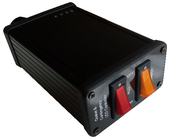
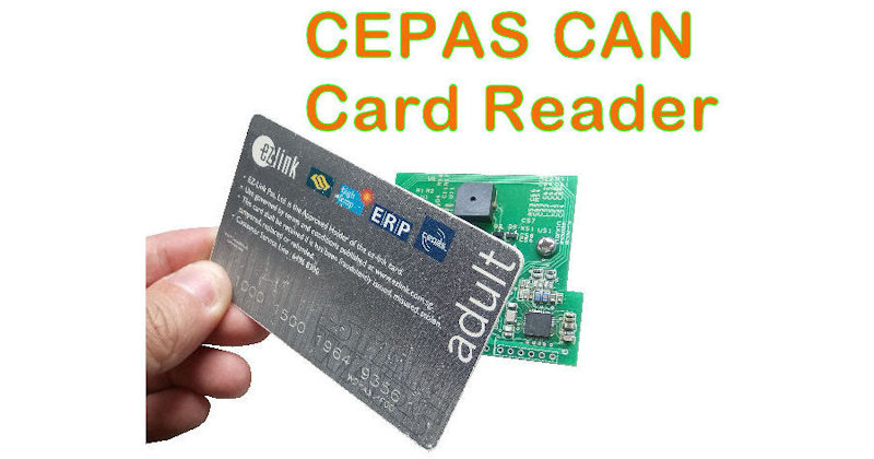
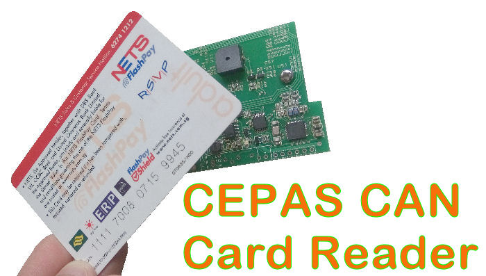
Check out this Card Reader for reading out the CAN number of local Singapore CEPAS cards, Ezlink or NetsFlashPay.
This card reader reads out the CAN number. A CAN number is a unique number which can uniquely identify the card.
Standard CEPAS CAN Card Reader Products
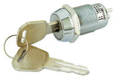
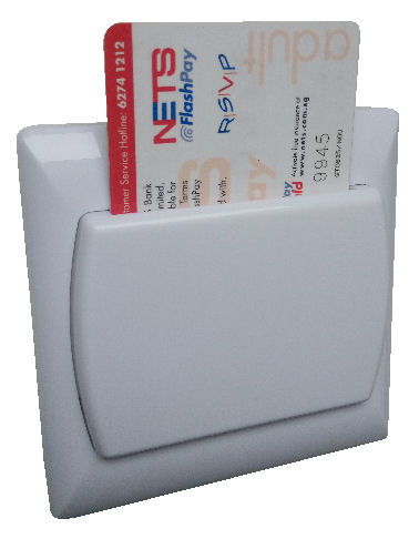
Card Key Holder(Energy Saving) |
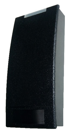
Door Access
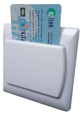
(Wall Mounted) 1) Wiegand |
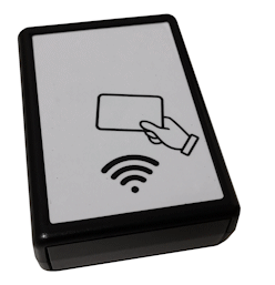
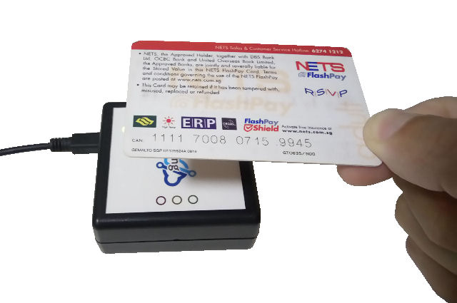
Desktop Reader(Guest Registration) 1) USB Keyboard [PIC-347-HID]
|
 |
 |
 |
 |
 |
 |
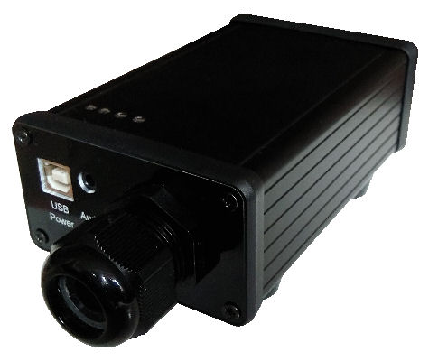
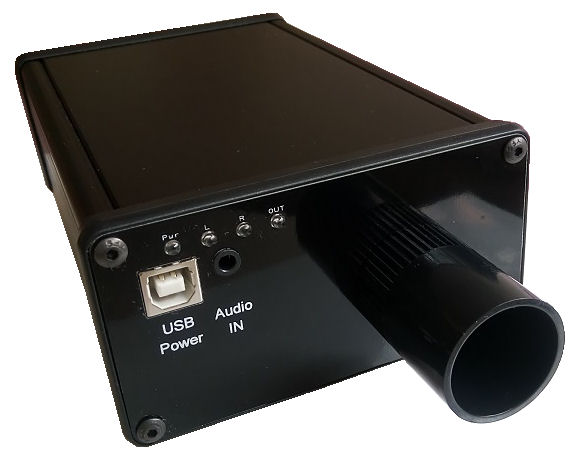
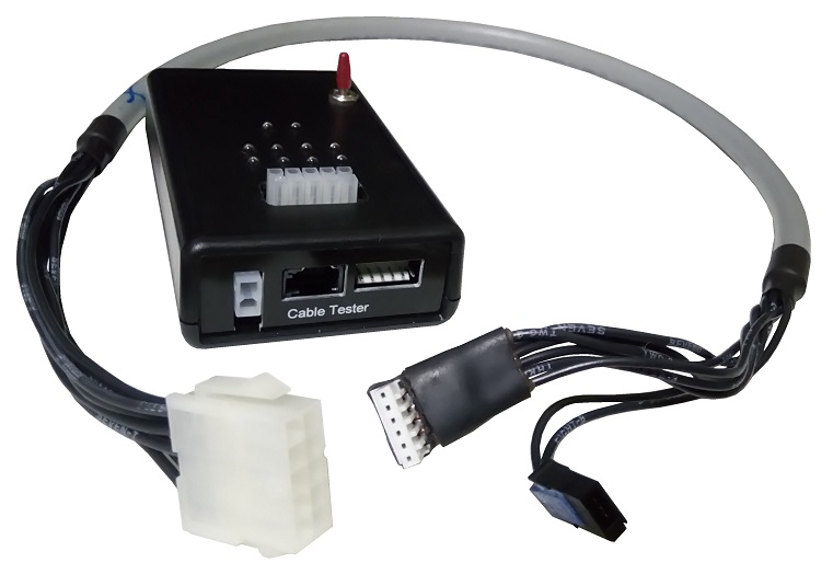
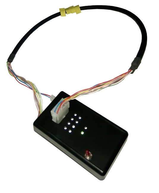
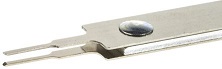
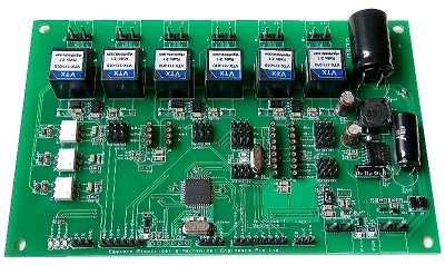
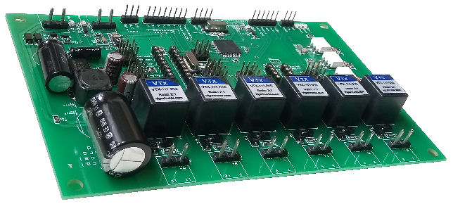
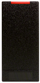
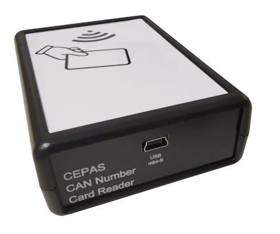
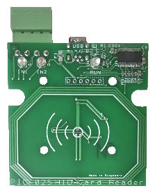
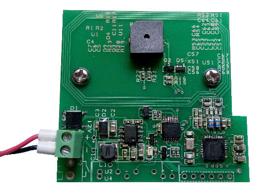
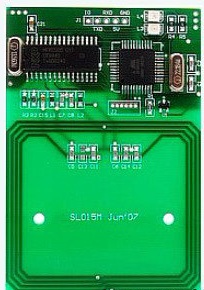
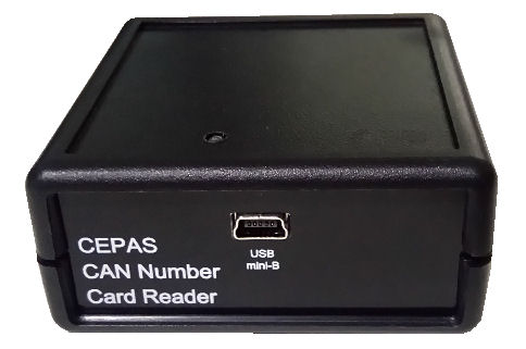
CEPAS CAN Number Card Reader
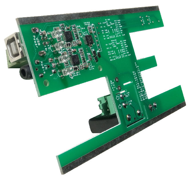
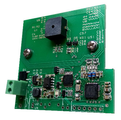
Circuit Board (Custom OEM)
This reader allows you to use publicly available cards (Ezlink, NetsFlashPay cards) for your own unique card ID application. It will save you the cost of issuing your own unique ID cards (which easily can cost you $50 per card holder). User also need not have to carry multiple cards with them.
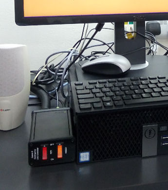
Typical Application
- Protect your visitor/customer privacy. Obtain unique ID of visitors or customers without revealing their identity card.
- Using easily available CEPAS card for permanent or temporary access to private rooms without issue new cards.
- In-house gaming or credit point system.
- Guest visitors registration.
- Membership registration and tracking.
If you are looking you are looking for a card payment terminal for your automated cashier, [you can click here and check out this page].
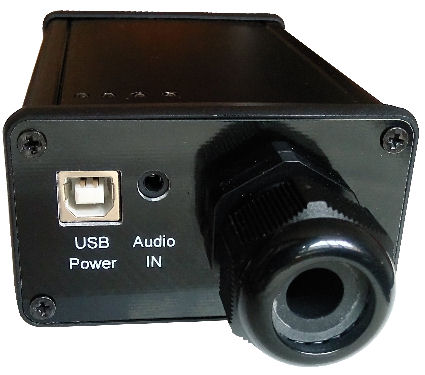
Features
- Communication connection (Custom option for Wiegand, RS232, RS485, Ethernet, USB Virtual Com Port, USB Keyboard Wedge)
- Instant readout of the CAN number (ASCII text) of the card.
- Buzzer feedback
- Read light indicator
- No need to install any software or driver (for USB Keyboard Wedge).
- Can act as an HID keyboard for spreadsheet or text file data entry (keyboard wedge application like a barcode scanner)
- User mode switch to select the operation mode
- Can be customised to read any type of 13.56MHz HF RFID cards.
This card reader can be custom programmed by our engineer to read other types of 13.56MHz RFID cards/tags. Some of the cards/tags are as follows,
- Mifare Ultralight (U1X), Ultralight C (U2X)
- Mifare Classic Mini (S20), Classic (S50), Classic (S70)
- Mifare Plus S (SPLUS 60), Plus S (SPLUS 80)
- Mifare Plus X (PLUS 60), Plus X (PLUS 80)
- Mifare DESFire EV1
- Sony Felica, Felica Lite
- NFC tags, NFC phone/device
- Emulate mode to emulate RFID tags
- ISO/IEC14443-3 Type A, ISO/IEC14443-4 Type A
- ISO/IEC14443-3 Type B, ISO/IEC14443-4 Type B
- NFC IP-1 mode
API and Software Technical Support
Guarantee software support to ensure everything works as you intended to be. Our engineer is ready to support and ensure that the reader that you purchase works on any of your software platform. We are here to make it work for your application.
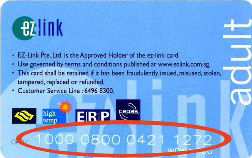
Ezlink Card (CEPAS CAN number)

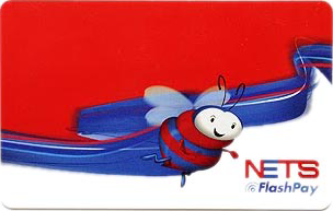
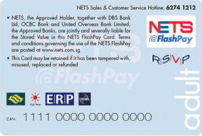
FlashPay Card (CEPAS CAN number)
CEPAS Compliance Cards (Co-brand)
The following types of cards can be CEPAS compliance. They can be used just like the card from Ezlink and FlashPay.
- Passion Card membership card
- Autopass Card (for Foreign Vehicle entering into Singapore)
- Selected Credit Card (Standard Chartered Unlimited, Citibank SMRT, POSB Everyday Card, FEVO)
CAN Number Allocation for CEPAS Cards in Singapore
A CAN number is unique allows you to identify the cardholder group category in Singapore. This helps to identify if the card is a normal transportation payment card or a concession card. Information is obtained from Transit Link Pte Ltd.
- 1000 xxxx xxxx xxxx (Adult CEPAS card)
- 1009 xxxx xxxx xxxx (Adult Co-Brand)
- 1111 xxxx xxxx xxxx (NETS Flashpay)
- 8000 xxxx xxxx xxxx (Concession cards: Child, Pri, Sec, Ter, NS, Senior Citizen)
- 8009 xxxx xxxx xxxx (Concession cards: Child, Pri, Sec, Ter, NS, Senior Citizen)
- 8008 xxxx xxxx xxxx (Concession cards: Child, Pri, Sec, Ter, NS, Senior Citizen)
- xxxx xxxx xxxx xxxx (SG Enable, Concession cards issue for the disability)
*** Note:
All concession cards do not allocate any specific CAN number for the different type of concession cards. This means that card number allocated by SG Enable will be the same number range as the other types of concession cards. For the specific organization card number range, please write in to that specific organization for more information.
Transportation Card Around The World
More transportation card around the world for your card reader customisation.
- Ezlink, FlashPay Card (Singapore)
- Octopus Card (Hong Kong)
- Touch ‘n Go (Malaysia)
- Edy, nanaco, taspo, Waon (Japan)
- Flazz (Indonesia)
- Metro Card (United States)
- Myki, Opal Card (Melbourne, Sydney)
- PayPass, PayWave, FarePay (Credit Card Payment Network)
For the cards that you want to custom the read, you can send in 3 or more card samples. Please write down the data or text that is contained in the card that you want to read.
Custom RFID reader
Contact PIC-CONTROL for your custom RFID reader today.
We can design the communication to fit into your system. It can be Ethernet, Wifi, Modbus, Zigbee, etc…