| Dated |
Project name & description |
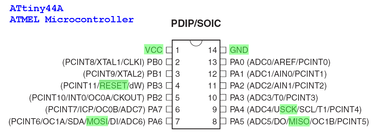
Microcontroller used/
Enclosure used.
|
IC chips and
special components used |
| |
|
|
|
| 2024-03-08 |
PIC-036
RS232 to Pulse Output
(4 Ports)
Fast-switching pulse output controller (Coin Acceptor Emulator) |
PIC16F18323 |
- LM3480-5 (regulator, wide input voltage range)
- MAX3232
- TLP185
|
| 2023-10-10 |
MDB Sniffer and Monitoring (for Vending machine protocol) |
PIC24FJ256GA702 |
- MIC2954 ADJ (LDO)
- MCP1700T-3302E/TT
- FT230XS-R
- HK19F-DC 5
- MCP6002-MS (op-amp for sensing signal buffer)
|
| 2023-09-22 |
CO2 sensor fan controller |
PIC24FJ256GA702 |
- LM22674MRE-ADJ
- LD1117
- AT24CS08
- TLP185
- MCP1416 (mosfet driver)
- FT230XS-R
- MAX3485
|
| 2023-02-12 |
PIC-030
Speed Queen Washer Dryer machine
interface board |
PIC16F18325 |
- LM22674MRE-ADJ
- MCP23017
- MAX3232
- AT24CS08
|
| 2023-02-11 |
PIC-121
Short Circuit Finder |
change PIC12F1840 to
PIC16F18313 |
- MCP1700T-3302E (voltage regulator)
- MCP73831 (Li-ion batt charge)
- MCP6041 (op-amp)
|
| 2021-06-26 |
Ju Teng Spectrometer project |
SparkFun Thing Plus |
- C12880MA
- TPS61023 (DC-DC pump up, LiPo 3.6V to 5V)
- LM22675MRE-ADJ
|
| 2021-06-17 |
PIC-340 I/O over DC Power Line |
PIC16F18313 |
- LM3480-5 (regulator wide input voltage range)
- PIC16F18313-I/SN
- THVD8010 (Pwr/Data transceiver)
- TLP185
- Relay G6K-2F
|
| 2021-06-17 |
Controller for motorised Trellis |
PIC16F18456-I/SS
microcontroller series that accept wide input supply voltage from 3.3V to 5V
|
- LM317
- LM22674MRE-ADJ
- MCP23017-E/SS
- BTN7960B (DC motor driver IC chip)
- MCP6C02 (current sense IC)
|
| 2021-05-11 |
Realtek, Proximity Switch Project |
Wall touch switch product |
- XC6206 P332MR (regulator)
- TTP223N-BA6 (capacitive switch, touch pad detector IC)
|
| 2021-01-15 |
RFID Trigger for Speedqueen Laundry Machines |
PIC12F1840 |
- LM3480
- YHY522 RFID module
|
| 2020-08-24 |
RFID Board Tester |
PIC16F18345 |
- LD1117S33
- MTCH102
- USBLC6-2
- FT230XS-R
|
| 2020-10-03 |
Door Controller |
(4 UART)
|
- G2RL-1E 12DC relay)
- (Memory)
- (RTC)
|
| 2020-09-08 |
Water valve controller |
PIC16F18325 |
- IRM-03-12 (AC-DC)
- LM3480 (wide range input LDO regulator)
- G2RL-1E 12DC relay)
|
| 2020-08-07 |
CEPAS Card Reader (Wiegand) |
PIC16F18325 |
no special parts |
| 2020-04-00 |
RS232 Sniffer |
|
|
| 2020-01-00 |
Humidity Controller |
PIC16F18345 |
- FT230XS
- HDC1080 (Humidity & temperature sensor)
- MTCH102
- MCP1700T-33
- P-ch
|
| 2019-11-12 |
Fraba Custom Cable Tester |
PIC24FJ256GA702 |
no special parts |
| 2019-09-10 |
PIC-029 Cashless Payment System
(See PIC-028) |
|
|
| 2019-09-09 |
PIC-029 Cashless Payment System for Arcade Token Dispenser Machine |
PIC24FJ256GA702
+ Touch Panel |
no special parts |
| 2019-09-08 |
Rain Sensor Controller,
with high voltage 230Vac line detector. |
PIC16F18325
Casing: 1593LBK |
- IRM-03-12 (AC-DC)
- LM3480 (wide range input LDO regulator)
- G2RL-1E 12DC relay)
|
| 2019-08-22 |
CEPAS Door Access Card Reader, PIC-346 CAN number readout
(RS232) |
PIC16F18325
Casing: SZOMK AK-R-08 |
- PN532 (RFID)
- MAX3232 (RS232)
- LD1117-3V3 (Reg)
- 24AA02UID
|
| 2019-00-00 |
CEPAS Door Access Card Reader, PIC-346 CAN number readout
(RS485) |
PIC16F18325
Casing: SZOMK AK-R-08 |
- PN532 (RFID)
- MAX3485 (RS485)
- LD1117-3V3 (Reg)
- 24AA02UID
|
| 2019-07-01 |
OG, CAN number reader |
PIC16F18325
Casing: 1593K |
- PN532 (RFID)
- MAX3232 (RS232)
- LM22674 (DC-DC)
- FT230XS (USB-UART)
|
| 2019-05-22 |
Port Loader Emulator
(ASYST) |
PIC24FJ256GA702
Casing: 1455L801BK |
- LM22674 (DC-DC)
- FT230XS (USB-UART)
- MAX3232 (RS232)
|
| 2019-03-00 |
Fong’s Product Cable Tester |
PIC24FJ256GA702
Casing: 1455Q1601BK |
- LM22674 (DC-DC)
- FT230XS (USB-UART)
- MCP1700T (Reg)
- MTCH105 (Touch)
- MCP23017
|
| 2019-02-28 |
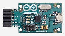
Microcool enclosure project arduino |
PIC16F18313
Customised enclosure |
- LM22674MRE-ADJ
- Arduino hat attachment board
|
| 2019-02-07 |
PIC-346 CEPAS RFID Door Access Card Reader |
PIC16F18325
Casing: SZOMK AK-R-08 |
|
2019-01-14
(FAILED) |
PIC-025 ver2.0 HID CEPAS CAN card reader
|
PIC16F1454
(USB microcontroller) |
|
2018-12-28
(FAILED) |
PIC-025 HID CEPAS CAN card reader
|
PIC16F18325 |
- FT260S (HID USB interface)
- PN532
- TLP185
|
| 2018-10-23 |
PIC-125 Audio Triggered Output Relay
|
PIC16F18325
Casing: 1593K |
- FT230XS (USB-UART)
- LMV324 (op-amp)
- RB751 (diode)
- Audio Socket MC001293
- Relay
|
| 2018-10-08 |
PIC-124 Alarm Mute Switch
|
PIC16F18313
Casing: 1593K |
- FT230XS (USB-UART)
- MCP1700, 3V3 voltage
- Relay
|
| 2018-07-12 |
Washing Machine Interface
+ MDB payment terminal connection.
|
PIC24FJ256GA702-I/SS
Customised enclosure |
- LM22674 (DC-DC)
- 24AA02UID (UID)
- FT230XS (USB-UART)
- MCP23017 (I2C I/O expander)
- more…
|
| 2018-06-25 |
Human Waste Controller
|
PIC16F18346
Customised enclosure |
- LM22674 (DC-DC)
- 24AA02UID (UID)
- FT230XS (USB-UART)
- MCP23017 (I2C I/O expander)
- more…
|
| 2018-04-00 |
RFID Room Card Key Holder
|
|
|
| 2018-04-00 |
RFID Reader for Room Access
|
|
|
| 2018-04-00 |
Cable Harness Tester
|
PIC24FJ256GA702-I/SS
Customised enclosure |
|
| 2018-03-00 |
RFID Hotel Card Key
Philipines
|
PIC16F18325 |
|
| 2018-03-00 |
Washing Machine Interface Board
|
PIC16F18345 |
- LM22674 (DC-DC)
- 24AA02UID (UID)
- MCP79400 (RTS)
- MAX3232 (RS232)
- MCP23017 (I2C I/O expander)
- TLP185 (opto-coupler)
- AQY210S (opto-coupler)
|
| 2018-01-16 |
Raspberry Pi 3 hat (attchmentment board),
RS232, RS485, IO, RTC
|
nil |
- LM22676 (DC-DC voltage regulator 3A)
- MAX3232 (RS232)
- MAX3485 (RS485)
- SC16IS740IPW (SPI to UART)
- DS3231M (RTC)
|
| 2018-01-16 |
SLA Battery Charger
Seal Lead Acid
Solar Panel + DC Power
|
nil
|
LT3652 |
| 2017-11-14 |
Heater element fault detector |
nil
|
- LM7332 (high voltage single rail op-amp)
- n-ch STP55NF06L
- 817 (opto-coupler)
|
| 2017-11-00 |
AMD CPU Chip Tester |
PIC16F18325
CY8C5868AXI-LP035
(PSoC5LP, ARM Cortex-M3)
|
- LT1963ES8 (Vreg)
- LT3083EFE (Vreg)
- LTC4365ITS8-1 (over voltage protection)
- LT3080EMS8E (LDO regulator)
- LTC2053IMS8 (Op-amp, voltage sense)
- LT6105IMS8 (current sense)
- MIC5209YM (LDO regulator)
- Si4946BEY (n-ch)
- FDV301N (n-ch)
- PCA9626B (i/o expander)
- FDN336P (p-ch)
|
| 2017-10-00 |
Water Treatment sensors and valve controller |
nil
Casing: Fibox PC 2118-3
|
- LM22676-ADJ
- LD1117-3V3
- MCP3424, ADC for voltage and current sensor (4-20mA)
- MCP6004, op-amp
- ADM3260 (I2C, UART, Power Supply Isolator)
- MAX3485
- 817 opto-coupler
Ver 2.0
- MCP4725 (DAC)
- XTR115 (4-20mA Transmitter)
- 24AA256 (EEPROM)
- IRM-30-AC-DC
(AC-DC 30 Watts)
- OMRON G3MB-202P
(solid state relay)
|
| 2017-10-00 |
Water Treatment touch panel |
PIC16F18325
Casing: Fibox PC 2118-3
|
- MTCH105, touch pad IC chip
- PCF8574APW, I2C I/O expander
- C5503ALNAK, AC switch (lighted)
|
| 2017-07-00 |
Electric Fence Voltage Tester from 0-15kV |
PIC16F18313
|
- 9V Battery
- TL431 regulator (low cost)
- p-ch, NTR4101PT1G, IRLML6402TRPBF to switch on power supply to itself.
- npn, BC847B
- pnp, BC857C
- HOLTEK HT1621B (TN LCD driver)
- 74HC164 (TN LCD driver)
|
| 2017-06-00 |
Cathodic Protection Driver |
dsPIC4013
PIC16C711, PIC16F716
PIC12C508A, PIC12F508
|
- VTX-111-010
- SN75477
- LTC1286
- LM2574-5
- H11L1
- BC108b
- BC182b
- SKKT 131-O8D 9515
|
| 2017-05-18 |
Audio Triggered Relay |
PIC16F18326
Casing: 1455N1601BK
|
- LMV324
- Solid State Relay D2410
- Audio Socket MC001293
|
| 2017-04-27 |
Cable connector assembly wire tester |
PIC12F1840
Casing: 1593QBK
|
- Enclosure 1593QBK with battery compartment (BS61)
- MCP23017, I2C I/O expander
- MCP1700, 5V voltage regulator
- 9V Battery
|
| 2017-03-28 |
Sensor and solonoid valve controller attachment board. |
—
Casing: 1455K1201BK
|
- Enclosure 1455K1201BK
- LM22676-ADJ
- PCF8574APW, I2C I/O expander
- MCP3424, ADC for voltage and current sensor (4-20mA)
- MCP6004, op-amp
|
| 2016-12-11 |
Motor Controller
BLDC and DC motor |
PIC16F18345 |
- LM2840, DC-DC voltage regulator
- A4950, DC H-bridge
- A4963, BLDC sensorless
- A4915, BLDC hall sensor
- IRF7343, n-ch p-ch MOSFET
- VOS617A-2X001T, opto-coupler
|
| 2016-12-02 |
Short Circuit Finder ver2 |
PIC12F1840
Casing: 1551G
|
- MCP73831, 3.6V Li-ion charger
- MCP1700T-3302, 3.3V regulator
- MCP6041, op-amp single rail
|
| 2016-11-30 |
Wire Feeder |
PIC16F18325 |
- LM2840, DC-DC voltage regulator
- MCP1703-3302, 5V regulator
- MTS2916A, Bipolar stepper motor driver
|
| 2016-07-08 |
OPB9000 Evaluation Board
- process 3x user push button
|
PIC24FJ64GA002 (28 pins) |
- OPB9000, IR optical sensor
- FT232BI, USB to UART
- XC6220, LDO regulator
|
| 2016-06-14 |
sd card audio player |
ATMEGA328P-AU (32 pins) |
- LM22676-ADJ, Switching Regulator
- XC6206P182, LDO
- XC6206P332, LDO
- IRF8707, n-ch
- TF card socket
- VS1053-L, Audio chip
- TDA7297, power amplifier
|
| 2016-04-21 |
RS232 coin acceptor trigger |
PIC12F1840 (8 pins)
(programmed with code protect)
|
|
| 2015-11-11 |
USB hub |
PIC16F1825 (14 pins) |
- USB2514Bi
- FT232RL, USB to UART
- VOS617A-2X001T, opto-coupler
- USBLC6-2, ESD protection
- RGB LED, Blue LED
- USB micro plug (PCB mounted)
- JST SR/SZ smd connector 1mm pitch
|
| 2015-08-26 |
Short circuit finder |
PIC12F1840 (8 pins) |
- MCP1700, LDO 3V3
- MCP73831, battery charger
- Op-amp single rail
- USB micro socket
|
| 2015-07-13 |
Health Monitoring Electronic |
PIC24F16KL402 |
- MCP73833, battery charger
- MIC5219, LDO
- MCP1700T-1802, LDO
- MAX30100, SPO2 IR sensor
- ADT7410, temperature sensor
- MMA7660FC, Accelerometer
- ESP8266, WiFi module
|
| 2015-05-20 |
Encoder Sensor, Speed Km/h Metering |
PIC12F1840 (8 pins) |
|
| 2015-04-28 |
Gaming Steering Wheel Control |
dsPIC30F3012 (28 pins) |
- FT232RL
- 33886, DC motor driver, H-bridge
|
| 2015-04-28 |
Traffic Light Controller (Singapore) |
PIC18F4550
Arduino UNO
|
- LD1117-3V3, LDO
- RFID reader module
|
| 2015-04-27 |
Battery Charger RS485 Status,
- multiple input monitoring
|
PIC18F4520P (40 pins) |
|
| 2014-08-08 |
BLDC motor controller |
PIC24EP256MC202 |
- LM22674
- MCP6L02T, op-amp for current sense
- IRF7343TRPBF, half bridge (n-ch p-ch)
|
| 2014-08-07 |
RFID Hotel Key Card Holder |
PIC12F1840 (8 pins) |
- RT9161A-33GV, LDO 3V3
- RFID reader module
|
| 2014-06-03 |
Automatic Gauge Block Comparator (NMC, MACCE) |
dsPIC33FJ256GP506 |
- MCP23S18, I/O expander SPI
- 24AA16, EEPROM I2C
- MCP9808, temperature sensor I2C
- LM22672, Switching Regulator
- LD1117, LDO 3V3
- Ethernet
|
| 2014-05-12 |
Security sensor array 2 |
dsPIC33FJ128GP804
PIC12F1840 (8 pins)
|
- EEPROM I2C (8 pins)
- LM22674, dc-dc
- MCP4725, DAC
- AD8629ARZ, OP-Amp single rail
- A (sensor)
- Ethernet
|
| 2011-00-00 |
Security sensor array 1 |
dsPIC33FJ128GP804
dsPIC30F2012
|
- LM22674, dc-dc
- LM22678, dc-dc
- EEPROM I2C (8 pins)
- MCP4728, DAC
- AD8629ARZ, OP-Amp single rail
- A (sensor)
- Ethernet
|
| 2013-09-03 |
Wireless Weighting Scale |
dsPIC33FJ128GP804 |
- LM22674
- EEPROM I2C (8 pins), 24AA16
- HX711, load cell reader
- XBee
|
| 2013-05-28 |
Wifi Sensor |
PIC24F08KL200 (14 pins) |
|
| 2013-03-27 |
Timer Pulse Generator Kit |
PIC12F1840 (8 pins) |
|
| 2013-01-04 |
Multimedia Player controller |
PIC12F1840 (8 pins) |
- MCP6L02T, op-amp for Piezo sensor
- IRF8707, n-ch
- IR remote control receiver interfacing
|
| 2012-12-17 |
PSI indicator exhibit |
PIC24FJ64GA004 (44 pins) |
- LM2575S
- HX711, load cell reader
- IRF8707, n-ch
- TM1804 IC for RGB LED
|
| 2012-11-12 |
Car park barrier gate controller |
PIC24FJ64GA004 (44 pins) |
- LM2575S
- LD1117
- MAX3232
- MAX3485
- Ethernet
|
| 2012-11-06 |
Alarm buzzer mute trigger switch |
PIC10F322 (6 pins) |
|
| 2012-10-08 |
RFID activated door & window |
PIC12F1840 (8 pins) |
- XC6206P302MR, LDO
- RFID reader module
- Wireless remote transmitter
|
| 2012-07-00 |
DTMF coder decoder |
PIC18F4550 |
|
| 2012-00-00 |
Factory Automation Controller (Visual Inspection) |
dsPIC33FJ256GP506 |
- LM2594, High Voltage step down switching regulator
- LM27313, DC-DC step up
- TPS76333DBVR, LDO
- 7seg LED
- EEPROM I2C, 24AA16
- MCP9700A
- Ethernet, RJ45
- RClamp0502A
- HX2019NL
- MAX3232
- MCP4725, DAC
- TS5A3159DBVR, analog switch
- MCP6H01, op-amp single rail
- sense resistor 50mOhm
|
| 2011-11-00 |
Ezlink payment to machine controller |
PIC24FJ64GA004 |
- LM2575S
- LD1117-3V3
- MAX3232
|
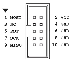


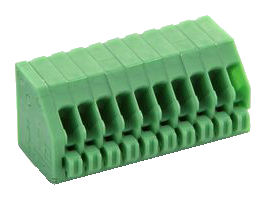
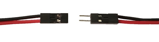
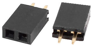
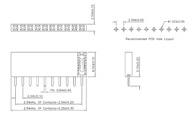
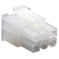
 IDC socket connector
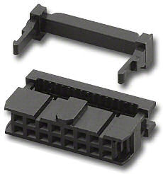
 IDC header connector
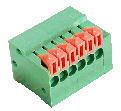
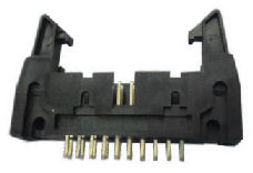 IDC header connectorwith side locking latch
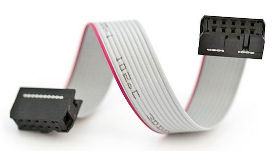
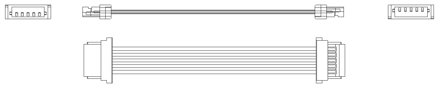
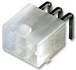
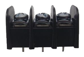
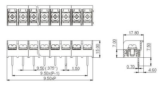

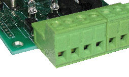
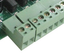
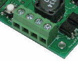
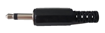
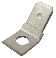 common tub width is 6.35mm.
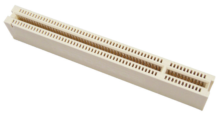

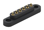

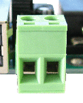
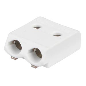
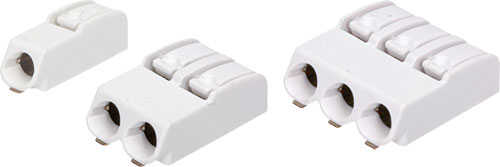
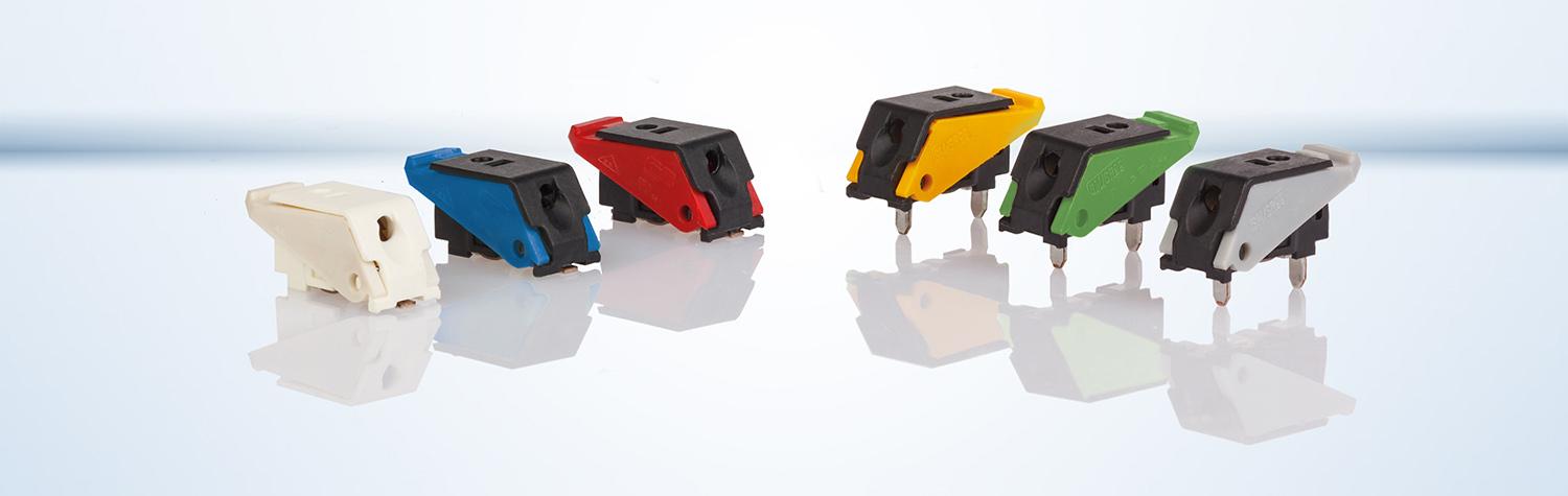
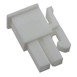
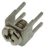
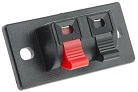 Quick Spring Release Connector for Audio Speaker Wires
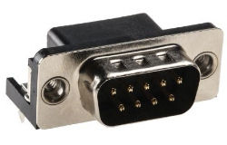 Pin 1 – Pin 5, Pin 6 – Pin 9
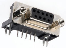 Pin 5 – Pin 1, Pin 9 – Pin 6
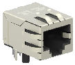
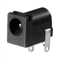
 Pin 1 – Pin 8
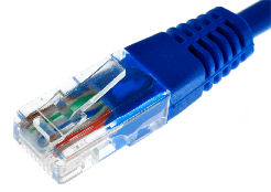
 Pin 1 – Pin 6