1.5mm pitch connector (JST, ZH series)

JST Connector (1.5mm pitch)     JST Logo

Japan Solderless Terminal (JST) 1.5mm pitch connector,
ZH series datasheet (0.17MB).

Current Rating 1A, up to 50V (AC or DC), (UL94V-0)
Suitable for small size board and small power. (wire size: AWG #32 to #26)

Header

1.5mm pitch connector

  • 3 Pos
    • B3B-ZR

Plug (Connector Housing)

1.5mm pitch connector

  • 3 Pos
    • ZHR-3

Pins

JST ZH series pins

  • SZH-002T-P0.5 (28 to 26 AWG)
  • SZH-003T-P0.5 (32 to 28 AWG)

Electronic Design Companies in Singapore

Looking for an electronic design house to help you design your electronic hardware products or prototype in Singapore?

We have summaries a list of electronic design companies that are located in Singapore that can help you with your commercial hardware development projects.

Electronic engineering has a very wide range of specialised discipline. It is a very big industry. Each electronic design house has its own area of specialisation and services cater for a specific group of customers or industrial sector.

PIC-CONTROL is an electronic hardware design company, specialise in data communication, control and sensor design in Singapore. Feel free to visit our website to understand more about our electronic design and engineering services that we are providing for our clients in Singapore. Or contact our sales engineer for further enquiry.


Check out the list of other electronic design companies providing hardware development services in Singapore,

Electronic Design Companies in Singapore


Electronic Design Companies (Overseas)

Malaysia

The overseas companies nearest to Singapore will be electronic design companies in Malaysia. There can be many iteration of discussion and meeting to finalised your electronic design requirements. Not as convenient and easy compared to engaging a local design company but it is your next best option. Given a choice it is still recommended to engage local design companies.

Most electronic design companies can be found in Kuala Lumpur and Penang (Malaysia). Check out this page for a list of electronic design companies in Malaysia.

Other Countries

For more electronic design companies, check out the following websites.


Contact PIC-CONTROL for your Electronic Design

Contact PIC-CONTROL for further discussion on your electronic hardware design today.

Or visit our website for more information on the electronic engineering services that we are providing for our local clients in Singapore.


Alarm Monitoring Panel Interface Board

RM20 Diodes PCB Circuit Board

RM20 Alarm Monitoring PCB Circuit Board

The RM20 is an alarming monitoring interface board in an electrical panel for remote monitoring of any fault status. Any fault detected will light up the indicator on the electrical panel.

An alarm can be trigger from this diode board when a fault occurred and is detected. The monitoring personnel can then be notified to resolved the detected fault.

This alarm monitoring board is designed to be compact with neat labeling on the board. There are jumpers for each connection which allows you to configure for the alarm activation. There is also a test connection which allows you to test and check if all the fault indicator is in good working condition.

Panel Alarm Monitoring interface board     Alarming Monitoring Interface Panel Board

RM20 Alarm Monitoring Interface Board

The alarm board is design using diodes which allow power to flow to the panel indicator on the monitoring electrical box. This diode board design helps to reduce the possible massive wiring work for the electrical box installation saving precious time and manpower costing. All diodes are surface which are located on the bottom of the board.

Alarm Monitoring Interface to Light Indicator using diodes

Alarm Monitoring PCB circuit board dimension drawing

The alarm monitoring board has a size of about 131 x 30mm.

This board is design to be stacked in a staggered top-bottom configuration so that it is easier for any technician to wire up the board. It is also designed so that this board can be mounted to a DIN rail using a standard DIN rail mounting bracket kit.

alarm monitoring circuit board drawing

Alarm Monitoring Interface Board (from Hong Lam)

RM20 Alarm Monitoring from Hong Lam Engineering

Alarm Monitoring Board from Hong Lam Engineering Pte. Ltd.

Or click here for LED Indicator Light Panel Board for monitoring the status of your 12V 24V electrical system.

PIC-CONTROL provides custom electronic design and production.

We can design a diode board for your project application.

Check out our website for more custom electronic engineering services

or solution to simplify your electrical box wiring.

1.25mm Pitch Connector (PicoBlade from Molex)

1.25mm pitch connector, PicoBlade 51021 Series from Molex


1.25mm pitch wire assembly (PicoBlade Molex)PicoBlade 1.25mm Pitch Connector (with cable)

Contact PIC-CONTROL for 1.25mm pitch connector wire assembly service.

PicoBlade Molex Connector (1.25mm pitch)     molex Logo

PicoBlade connectors from Molex.

Current Rating 1A, up to 125V (AC or DC)

Header

Molex PicoBlade 1.25mm Header (2 Pos Contact)

51047, 53047, 53048, 53261, 53398

  • 2 Pos
    • 53047-0210
    • 53398-0271
  • 3 Pos
    • 53047-0310
    • 53048-0310
    • 53398-0371
  • 4 Pos
    •  53261-0471
  • 5 Pos
    • 53047-0510
  • 6 Pos
    • 53048-0610
  • 8 Pos
    • 53047-0810

Plug (Connector Housing)

Molex PicoBlade 1.25mm Receptacle (3 Pos Contact)

51021 Series

  • 3 Pos
    • 51021-0300
  • 4 Pos
    • 51021-0400
  • 5 Pos
    • 51021-0500
  • 6 Pos
    • 51021-0600
  • 8 Pos
    • 51021-0800

Pins

PicoBlade crimp pin (26 AWG)

  • 50079 Socket Crimp (26 AWG, tin plated contacts)
  • 50058 Socket Crimp (28 AWG, phosphor bronze contacts)


Custom Wire Assembly Service

Contact PIC-CONTROL for custom wire connector assembly service.


Click here to return to Connector Singapore page.

Water Level Detector Electrode System

Water Level Detector Relay Board

Water Level Detector System

water level detector system panel

This is the distribution box for the water level detector system using electrode sensor, design and built by Hong Lam Engineering Pte. Ltd. .

The system consists of a total of 8 electrode sensor for 2 water tank. Each tank has electrode sensors of 4x different length to detect the water level.

When the water is too low, a water pump can be activated to transfer water to/from the tank. An emergency sensor is also position to prevent the water level being too high which can result is water overflow damage. The water level system is completely automated through the electrode sensors and pumps system.

The water level system is also wired up with indicators to alert the user. Remote monitoring can also be implemented so that the status can be monitored from a central control room.

The electronic control boards can be wired accordingly for your own water level control.

Contact Hong Lam Engineering to buy this water level detection system.


Click here if you are looking for other types of water level sensors for your project.

Wiring Diagram for Electrode Water Level Detector System

water level detector wiring diagram

Water Level Detector Control Boards – for Sale

The water level detector system consist of 3x electronic circuit boards which provides the automation control. They are namely,

  • Flow Switch & Auto Change-Over Relay Board
  • Water Level Detector Relay Board
  • Water Level Electrode Sensor Board

Flow Switch & Auto Change-Over Relay Board

water flow switch control relay board

The water flow switch board detects the water flow and will activate the system accordingly.

Water Level Detector Relay Board

water level detector relay board

The water level detector relay board consist of 8 relays. Each is activated by the connected electrode sensors that are detecting the water level. When a water level is detected, the relay will be active, hence allowing the system to activate pumps, motor, etc… or alarm to alert the user.

The interface is simple to understand and the wiring is easy to connect.

Water Level Electrode Sensor Board

water level electrode sensor board

The water level electrode sensor board, connects up the 8 electrode sensor. 4 electrode sensors will be used for each water tank. The 4 electrode length will be at their respective water level, each indicating the following staus,

  • common
  • low water level cut-off
  • restart level
  • emergency level


Clearance Sales !!!     (for a Limited Time Period Only)

Buy Your Water Level Detector System Now

Flow Switch & Auto Change-Over Relay Board

click on the picture to view larger image.

Stock Qty: 96

Flow Switch & Auto Change-Over Relay Board with cable connector

Flow Switch & Auto Change-Over Relay Board

Water Level Detector Relay Board

click on the picture to view larger image.

Stock Qty: 191

Water Level Detector Relay Board

Water Level Detector Relay Board connector     Water Level Detector Relay Board, high voltage

Water Level Electrode Sensor Board

click on the picture to view larger image.

Stock Qty: 163

Water Level Electrode Sensor Board with cable connector

Water Level Electrode Sensor Board     Water Level Electrode Sensor Board


For purchase of this water level detection system or further information on the installation,
please contact Hong Lam Engineering Pte. Ltd (Your Specialized Pump Contractor).

Price will be discussed.

Also check out the other sensor electrodes, pumps and accessories product and services offering at their website (http://hlameng.com).

Hong Lam Engineering


Click here to explore more water level sensors and technologies.

Water Level Sensor

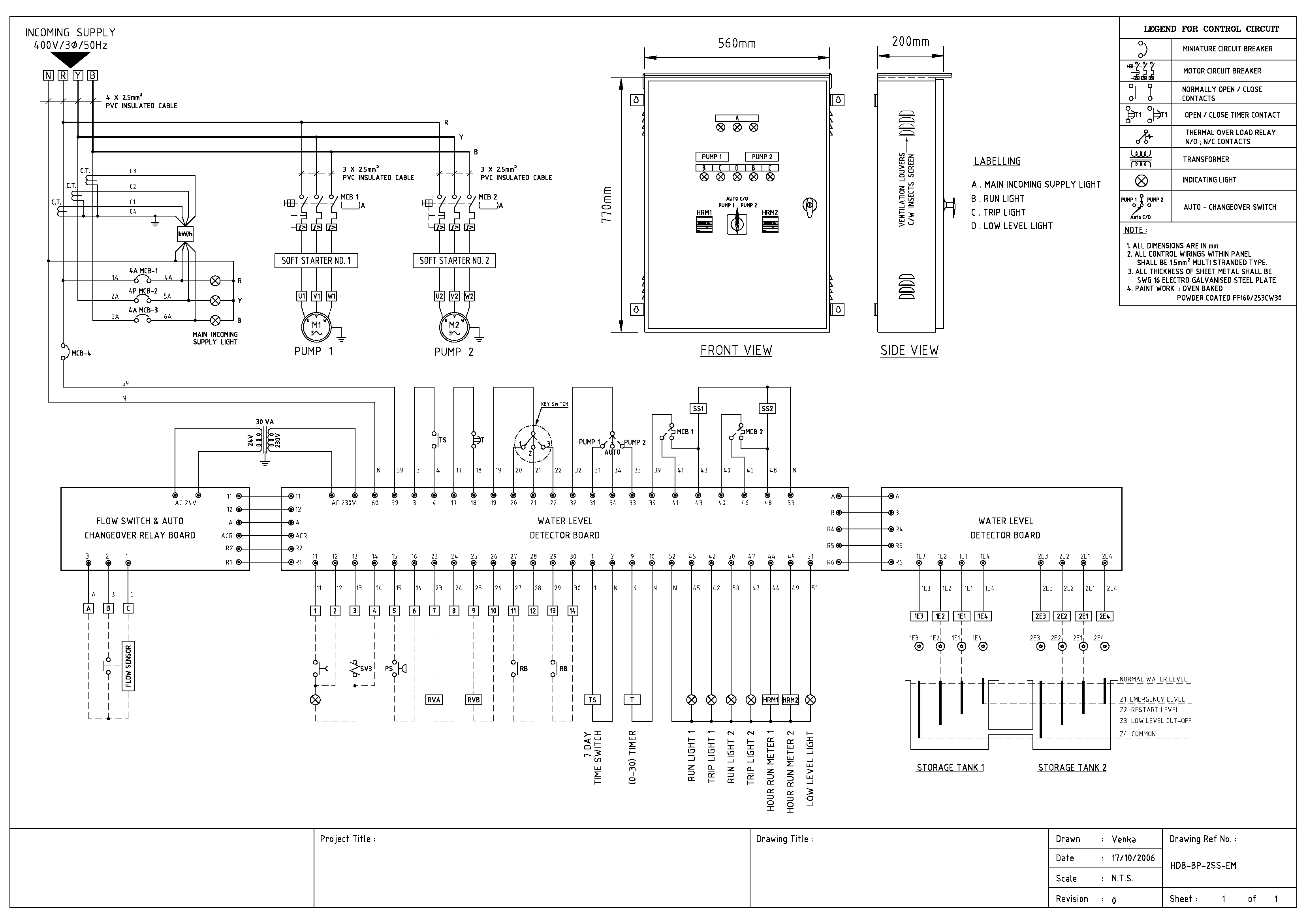
This page provides a short write-up of the various types of water level detection sensor available. You can click on the individual links which provide a more detailed description of the particular water level sensor, or you can visit the compare page to have an overview comparison of the water level sensors.

Type of Water Level Sensor

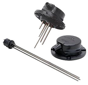
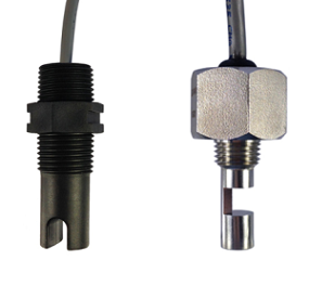
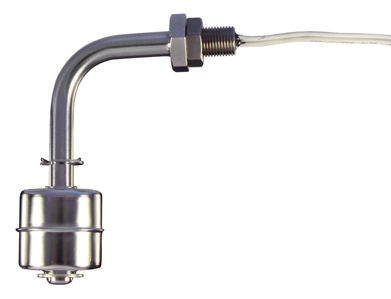
Electrode Water Level Sensor

eletrode sensor holder from Omron

Water Level Electrode Sensor Holder from Omron.

$120. (holder for water sensing rod)

Water level detector control panel for sale

Fully automated water level control system for water tank. Electronic control circuit board for electrode water level sensing.

Click here to check out this low-cost electrode water level detection system available for sale at a from Hong Lam Engineering Pte. Ltd.

For more information about an electrode water level sensor, click here.

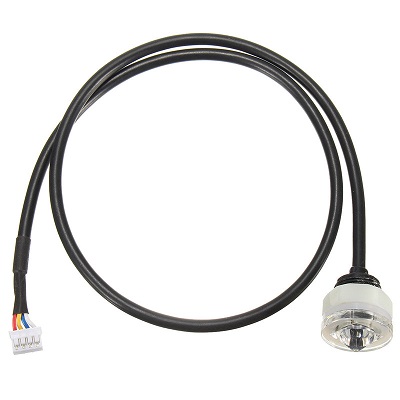
Optical Infrared Water Level Sensor

Optical water level sensor work with the principle of light refraction. Light is internally reflected. When in contact with water, the light ray gets refracted out of the sensor. The reduce light intensity through internal reflection indicates the presence of water, hence water level is detected.

The sensor is usually mounted on the side of the tank to detect water level. Water is required to be in contact with the sensor in order for the sensor to work.

Optical IR Water SensorOptical IR Optical Sensor (Stainless Steel)

http://www.fluidswitch.com/blog/how-do-optical-level-sensors-work/

Datasheet: water sensor for water level detection.pdf (filesize: 1.3MB)

Ultrasonic Water Level Sensor

Ultrasonic water level sensor works by emitting a sound wave pulse and listen to the reflected wave (like how a bat detects its surrounding). The time it takes for the reflected sound wave to return determines the water level.

The sensor is usually mounted on the top of a water tank, with the emitter facing downwards. The water surface will reflect the emitted wave back to the sensor. If the sound wave takes a longer time to return, the water level is low. A shorter time for the reflected wave indicates a higher water level in the tank.

The advantage of using an ultrasonic sensor for water level detection is because the sensor has no contact with the water or any other liquid in the tank. There is also no need for any drilling or installation on the water container tank.

Ultrasonic Water Level Sensor

http://www.fluidswitch.com/blog/pros-cons-ultrasonic-level-sensors/

Check out further information on using the ultrasonic sensor for water tank level detection application.

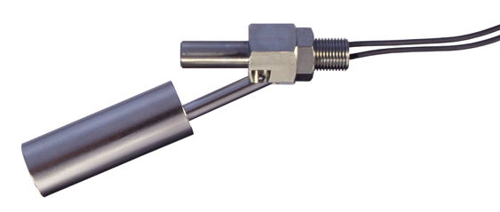
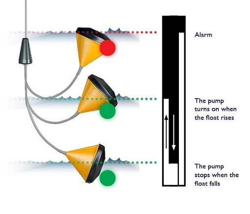
Float Switch Water Level Sensor (magnet)

A float switch is a simple and cheap way to implement a flow level detection system. The switch is activated by a float which will get lifted up by the water. This float switch sensor is sealed and waterproof. The lifted float contains a magnet will then activate a reed switch on the wiring end. The activated switch can then be used to trigger or stop motor pumps.

If you need to have a multiple water level indicator, you will need to install more than one of this float switch. This sensor can only sense the water level when the water reaches the level where the sensor is installed.

Float switch water level sensor (Stainless Steel)Float switch water level sensor

http://www.fluidswitch.com/horizontal-float-switches.php

On the market, there is also a newer advance water level float switch sensor. The working principle is similar, except that this single float sensor contains multiple switch point depending on the water level.

You can detect multiple float level using only on of this advance float switch, which allows you to implement an automatic water level control system, without having to install multiple sensors.

multi level float switch water level detector

http://www.kari-finn.fi/index.php/En/products/float-switches/pintakytkimen-valinta-en

***Check out this page for more information on using a float switch for detecting the water level in a water tank.

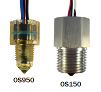
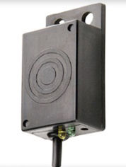
Capacitive Water Level Sensor

Capacitive water level sensor works by detecting the change in capacitance on the surface of the sensor. This allows the sensor to be mount outside of the water tank or pipe, without having to be in contact with the water.

capacitive water level sensor

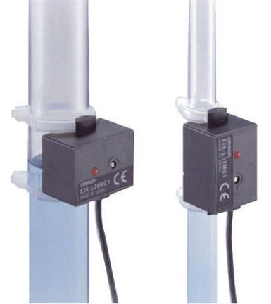
https://www.ia.omron.com/products/family/475/

capacitive water level sensor     capacitive water level sensor

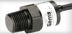
http://www.gemssensors.com/Level/Single-Point-Level-Switches/Capacitive

Selecting a Suitable Water Level Sensor

You can also check out this water level sensor comparison table to help you select a suitable sensor for your water level detection system design.

Flood Water Level Sensor Solution

For a custom water level solution for your water tank or water detection system, you can send in your enquiry to PIC-CONTROL.

Evaluation Kit Development

Looking for a design house to develop an electronic hardware evaluation kit for your customer to shorten their product development time?

A well design evaluation kit can help your client understand the edge your product has to offer. A good electronic evaluation kit has to be simple to use, and it has to enhance the feature of the product that you are selling. The aim is to reduce the barrier for your client which allows you to clinch your deal with them.

Design and Develop evaluation kti for customers Sensor evaluation board developer

Evaluation Kit for a IR sensor. USB connectivity from a computer with simple display that your client can interact with.

Evaluation Kit Design Schematic

Evaluation Kit PCB Layout Design

We would like to hear from you, and help you design your electronic hardware evaluation kit for your client.

Easy and simple for your client to understand so that they can shorten the time to understand your product.

Contact PIC-CONTROL today.


Also, check out our other electronic design services from PIC-CONTROL in Singapore.


Reduce Electrical Wiring for DB Box

Electrical wiring may seem to be a simple job, the scale of the work is typically massive. The wiring job for a home or an office can take days to complete. Any slight wiring improvement can often help save a lot of time and cost.

No More Messy Cables Wiring !!!
Electrical wiring in a mess.

Print your wiring onto a PCB (Print Circuit Board) to

  • reduce Size and Weight.
  • reduce Assembly and the number of Connection.
  • reduce the Wires materials, components.
  • easier to handle.
  • reduce Production Time.
  • reduce Man-hours manpower.
  • reduce your Production Cost.

Distribution Box (Electrical DB Box)

Connecting a wire termination in the DB box may take less than a minute of work. When connecting thousands of wire termination, the work can take days to complete. Reduce and simplify wiring work can significantly improve your efficiency and man-hour cost.

Wiring in the DB box forms the connections between termination to achieve a function. If your wiring function is consistent and repetitive, you may like to consider fabricating a PCB board to reduce the massive connection work. Not only can it save you time in your man-hour, but your wiring will also be neater, saving your significant cost in the long run.

Wiring board for electrical wiring connection (front).Wiring board for electrical wiring connection (back).

Reduce electrical wiring connection in a DB box using PCB board.

PCB board reduce wiring for electrical box     Elco wiring board example.

A simple board from Elco to help reduce distribution box wiring connection.

Reduce Wiring Cost

A significant of the project cost can be due to the massive amount of wiring laid across a distance of 100m or more. If your cable is only used for signalling, and not for the purpose of delivering power, there is a chance that your cable can be further reduced, saving you on the cabling cost.

PCB drawing for simplify electrical wiring connection.     PCB wiring drawing for electrical panel

Send us your electrical wiring/cabling problem that you have onsite. We can help you assess a solution to help you improve your efficiency and reduce your costing.

Contact PIC-CONTROL now.

Check out other related products which is design to help you reduce your wiring work in an electrical box.
Alarm Monitoring Panel Interface Board
LED Indicator Light Panel Board for monitoring the status of your 12V 24V electrical system.

Check out our home page, PIC-CONTROL, your electronic design and manufacturing provider in Singapore.

Electronic Part Shop Near Me

Click on the bracket to view larger map for electronic related shops in Singapore.

Click here to check out the electronic components shops page for the address and the details.

Central

  • Sim Lim Tower, (opening hours 10am-6pm Mon-Fri, 10am-1pm Sat, Closed on Sun)
  • Sim Lim Square
  • Jalan Besar Plaza
  • People’s Park Centre, Chinatown (KOBA Electronics)

North

  • Woodland (sgBotic)

East

  • 15 Tai Seng Drive (element14), (opening hours 9am-6pm Mon-Fri, Closed on Sat & Sun)

West

  • nil

Learning Basic Electronic (Hands-On-Approach) Crash Course Syllabus


Electronic Crash Course (Singapore)

Introduction

This is a crash course which provides students who have the interest in building electronics projects but do not have any formal education in electronic engineering, to have the fundamentals which empower them with the confidence to hands-on electronic in a systematic and practical manner.

Summary

  • Basic practical electronic.
  • Teaching step by step how to diagnose and troubleshoot the circuit.
  • Consultant and technical support offline.
  • Course material will be made available online.

Lesson 1: Soldering and Simple Electronic (2 to 4 Hours)

Learn basic electronic theory. Learn good soldering practice and manually fabricate a board with switch and LED.

Objective:

  • Identify components and symbols (resistor, LED)
  • Simple Ohms Law Theory (Voltage, Ohm, Current, Wattage), -> V/ohm = A
  • Learn how to use a power supply and digital multimeter
  • Soldering Theory
  • LED Circuit
  • Solder LED circuit.
  • Switch Circuit
  • Solder Switch circuit.

Tools required:

Equipment

  • Bench power supply
  • Multimeter

Soldering Equipment

  • Soldering iron
  • Solder (0.6mm, 0.8mm)
  • Solder Paste
  • Tweezer
  • Crocodile clip wire
  • Wire stripper, cutter, plier
  • Crimping tool
  • Hand Drill (1mm, 3.2mm drill bit)

Materials

  • Prototype board (doughnut pad, single side)
  • Wire wrapping wire
  • Resistor LED, through hole / SMD components (small/big, fresh/oxidise)
  • Turn pins socket (through-hole resistor for LED)
  • Screw Terminal (2pin, 5.08mm)
  • Header pin (test pin)
  • Crimping pins, Housing
  • Wire (7/0.2mm, Black, Red)
  • Ferrule
  • Wire heat sleeve
  • Toggle Switch
  • Push button (PCB mount)

Others

  • Laptop
  • 5V, 3V3 power supply

Lesson 2: Soldering and Simple Electronic (2 to 4 Hours)

Objective:

Learn component selection and power distribution.
Using transistor and relay as a switch.
Design (schematic drafting) and manual fabricate a test board.

Electronic

  • Identify components and symbols (capacitor, inductor, diode, transistor, IC chip)
  • Identify component package (SMD 1206 0805)
  • Learning how to use transistor and relay. Using the transistor as a switch.
  • Learning to read transistor datasheet. How to look for a transistor for your project.
  • Learn to dig for resource and learn electronic parameters from Element14
  • Industry standard size, standard rating (LED 20mA, resistor 1/8W, 1/4W)
  • Current distribution computation to the circuit module. (Power design and distribution) How to buy a power supply?

Typical things that you may look out for in a datasheet.

  • Absolute Maximum
  • Operating Voltage
  • Current Consumption

Learn by copying and replicating electronic circuit.

  • Memorising Switch/LED circuit
  • Recognising standard circuit.
  • Learn to read a schematic

Troubleshooting procedure

  • check power voltage
  • check all expected component voltage on a schematic.
  • isolated problem
  • test component.

Lesson 3: Arduino I/O Interface (2 to 4 Hours)

Objective:

Introduction to microcontroller datasheet in an Arduino, pin mapping and I/O. Design schematic from student’s project requirement, step by step. Sensor NPN/logic interface, Output relay/transistor control, ADC, solenoid

  • Concept of looping
  • Hello world blinking LED (LED PWM)
  • Switch programming (switch glitches)
  • Motor control, speed control.
  • Using I/O LED indicator for debugging purpose.
  • Selecting transistor to run LED, Motor, Relay

Lesson 4: Arduino UART (Communication with a computer)

Objective:

Learn digital numbering system, Hexidecimal. AND, OR, NOT, XOR UART theory.

  • build a UART interface to observe data transmission
  • learn oscilloscope
  • push switch glitches
  • writing delay()
  • ADC
  • Bluetooth, Ethernet, WiFi

Tools:

  • Computer
  • USB to UART
  • Oscilloscope (visual aid)
  • LED

Reference:

Lesson 5,6,7: Mini project that uses I2C, SPI Sensor

Objective:

  • Dynamic teaching.
  • Evaluating the student knowledge and teaches them as they do their project.

Project Examples:

  • DC motor control
  • PWM, lighting brightness control
  • I2C related sensor
  • SPI related sensor

Optional Topic:

  • Arduino Interrupt
  • Timer

Spending time troubleshooting with the students.


Electronic Crash Course in 24 Hours
Private Training Cost Fee at $3500 + GST

Contact PIC-CONTROL to personalised your electronic crash course.


Click here to access a collection of self-learning electronic resources.