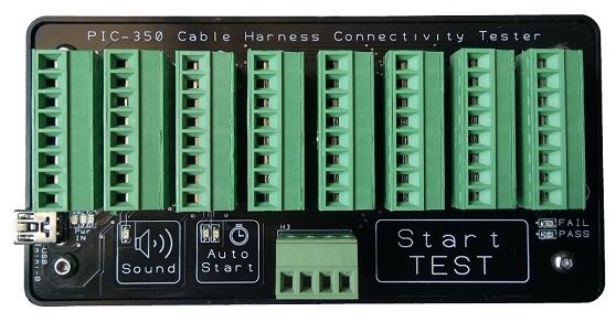
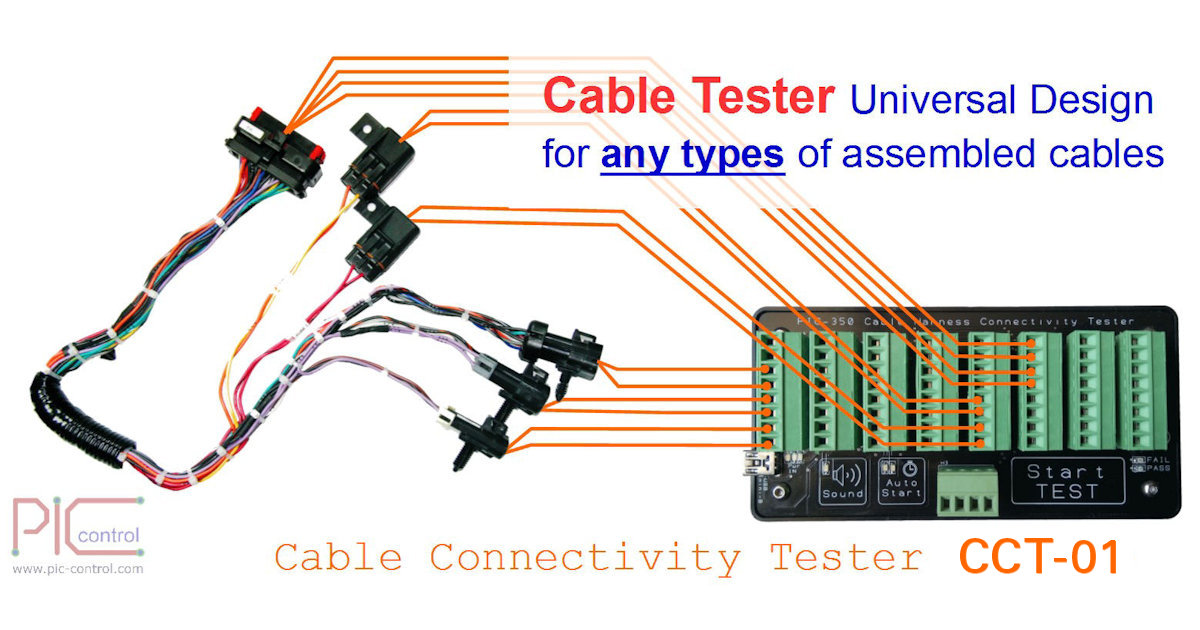
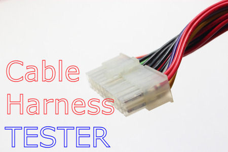
CCT-01 Cable Harness Connectivity Tester
Efficient cable testing tool that you must have for your cable production and maintenance work.
Check out ![]() www.cable-tester.com for more information.
www.cable-tester.com for more information.
Application
Improve your efficiency and quality of your cable harness assembly production using this cable harness tester. Fast checking to ensure that your harness wiring is done correctly by your operators.
- Testing of cable harness connectivity for your production line.
- Reverse engineering of any unknown cable wiring connection.
- A portable tester for onsite cable checking.
- Using it as an electrical wire tester to check for electrical connection.
- Automated connection checking on PCB board.
- Multiple wire cable tester.
- Test setup to capture intermediate cable issue due to broken or loose wiring connection.
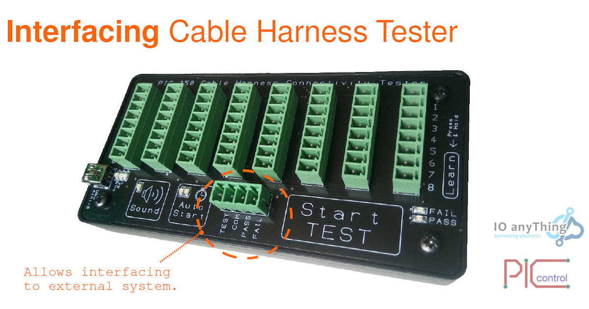
This cable tester is also designed for interfacing to your existing equipment machinery and computer to allow for a fully automated testing system.
Advantages
- Reduce production time.
- Reduce labour cost.
- Improve quality with reduced defects.
- Suitable for small to large scale cable production
Video Demonstration
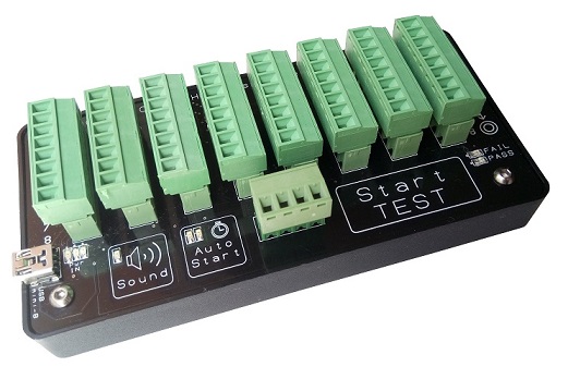
Simple To Use
This cable harness tester is designed to be simple to you. You can train the tester with your working set of cable harness. The tester will base on this master cable harness to test if the subsequent cables.
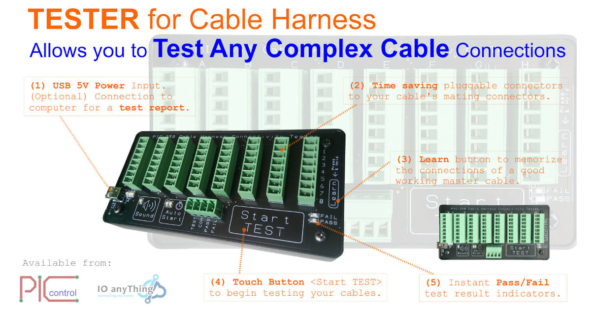
To make your testing production process easier, you can connect the mating connector for your cable harness to the tester first. This allows you to connect your cable harness faster to the tester. You can connect the wire to any terminal. There is no specific port to connect because this tester can self-learn your cable connection. Simply ensure that all your wires are connected to one of the screw terminals. The tester can learn and memories the connection of your good working master cable harness connection.
Once the tester has learned the wiring connection from your cable harness, you can start to test your production cables using the same connection. A green light flash indicating “Passed” means that the cable matches the master cable connectivity. A red light flashing indicates a “Failed” test. There will also be a beep sound option to allow the operator to know the test status without them having to pay attention to the light indicator.
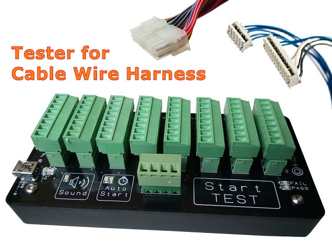
Basic Features
This cable harness tester provides the basic testing of your harness wiring connection to your connectors. Ensure your production quality by checking all the connection on your cable harness.
- Low-cost cable connection tester kit.
- Checks all open/close connection between all the wire terminals on your cable.
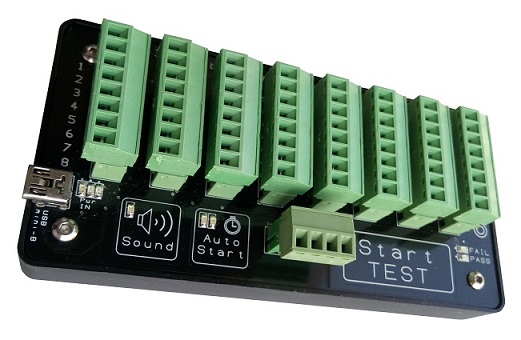
- Small size, light weight (easy portable).
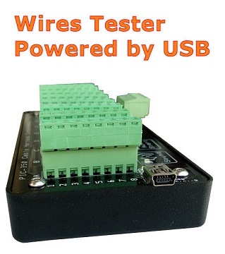
- Power using USB from wall plug or via portable power bank.
- Beep sound alert (enable or disable).
- Auto-start testing when the cable is connected or manual press button to start.
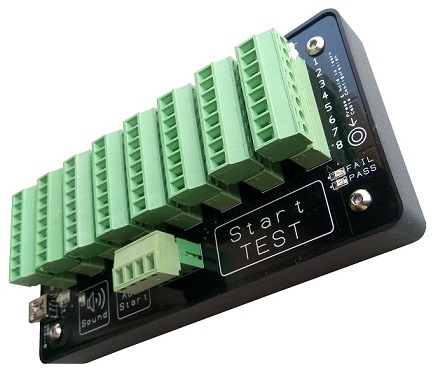
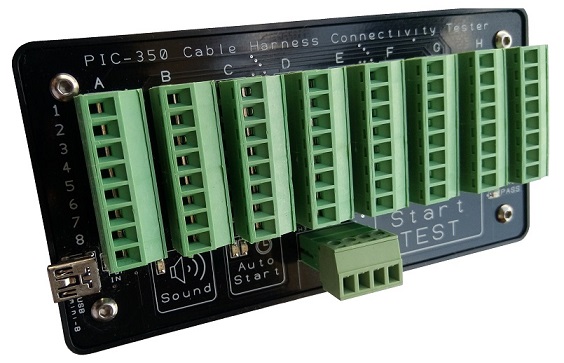
- Screw terminal to allow you to easily setup with your own connector for your cable harness test.
- Master connection learned will still be retained after power-off.
- Generate test report for you to see the connection of unknown wiring for your documentation.
- Test setup to capture intermediate wire connection problem.
- Test up to 64 connector’s termination points/nodes per tester. For more then 64 points, you can link-up with multiple CCT-01 tester.
- External interface allows tester to be controlled with your automated machine or link-up with multiple CCT-01 tester.
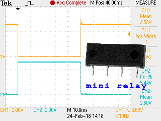
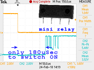
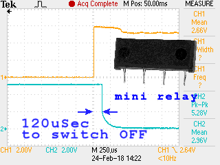
The test method implemented in this cable tester uses pulse signal through each and every pin to detect if a particular connection is open or close. The continuity result will be checked with the learned master connection to determine if the connection is correct.
General purpose cable connection continuity checking. The screw terminals provide you with the flexibility to use this tester for any of your cable harness connectors. If you prefer to have a specific connector tailor-made for your cable harness assembly, you can contact us for your customisation.
Generate Connection Test Report
This cable tester operates with just a simple USB power supply. When connected to a computer/laptop the tester can display a detailed connectivity report of the assembled cable harness. You can use this report to find out how this cable harness is assembled, how each individual pins is connected to each other. A handy instrument tool for reverse engineering of any unknown cables.
Click here for more information about this cable tester.
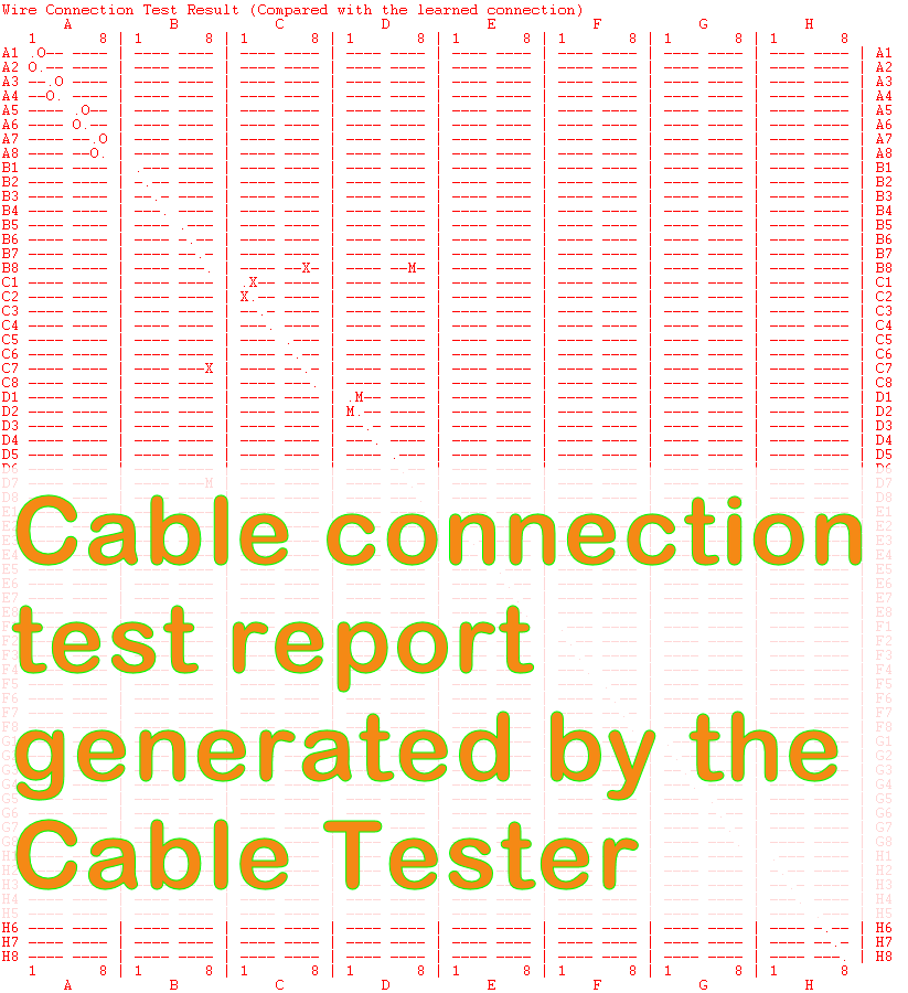
<- Cable Test Report generated from CCT-01 Cable Tester
Enhance Features
- View details test report using a computer or laptop via the USB connection.
- Allows interface to an external switch or light indicators.
- Allows cascade of more testers to test for more wiring connection.
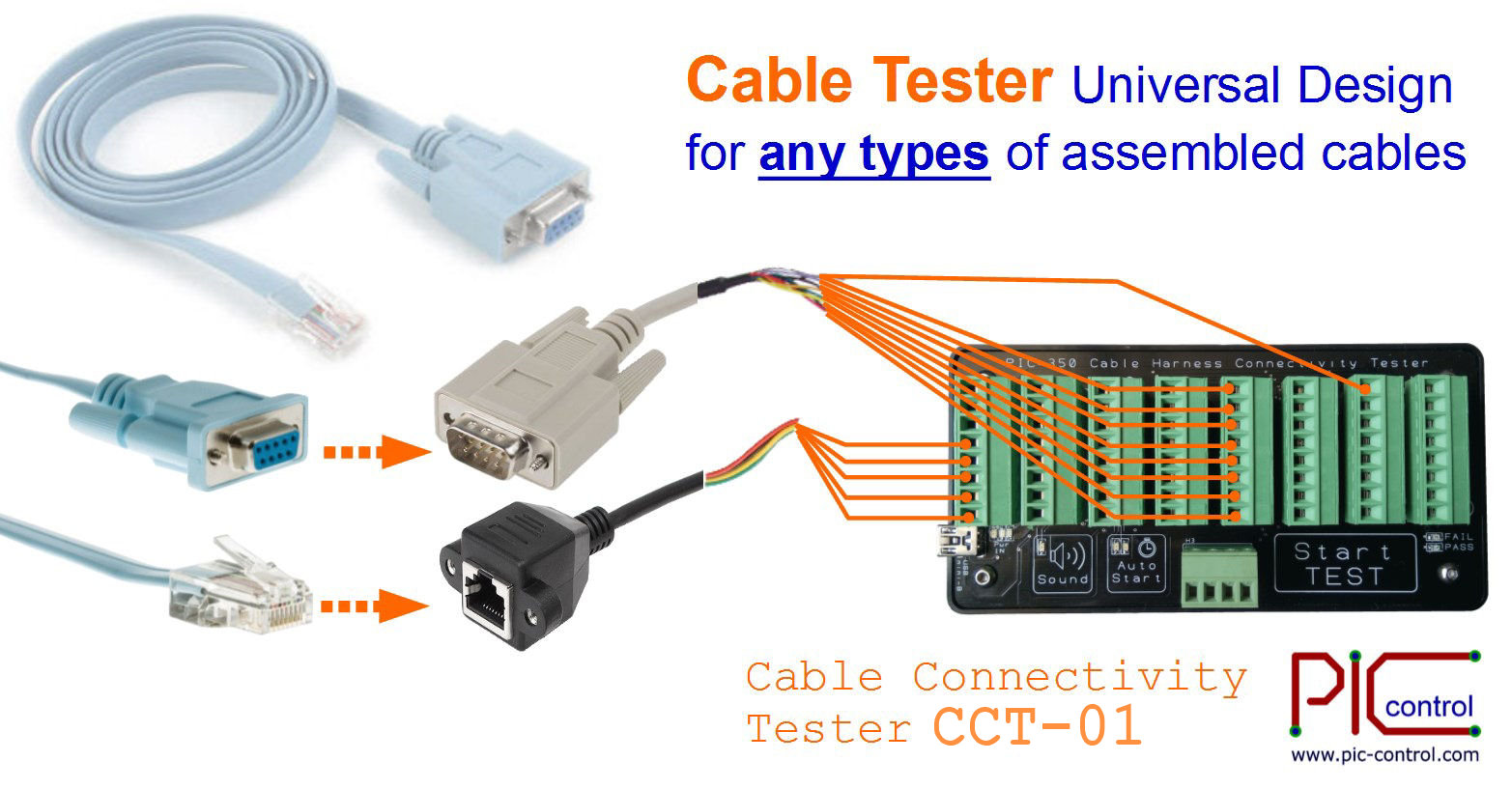
Typical Tester Application Guide
D-sub and RJ11 connector connection test setup
Click here for more information about the cable test setup procedures.
Custom cable harness wiring connectivity test setup
Custom cable tester design service
We can custom made to have your connectors on board so that
it is neat (without connecting wires) and cater specially for your particular cable harness.
The tester can also be designed with a PCB board adaptor. This allows you to swap the connector type to match the connector of your cable harness assembly. It can also be custom made to fit your test jig fixture or machines, to allow for a fully automated production system.
Customised your productivity tool today.
For a customised wire connection testing for your unique cable’s connector, please contact us with your design requirements.
Other Custom Tester Services
Click here for more other cable harness tester products.
Price (Order Yours Today)
Click here to check for price and purchase.
Check out ![]() www.cable-tester.com for more information.
www.cable-tester.com for more information.
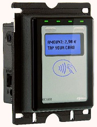 iUC180 Payment Terminal
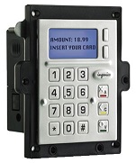 iUP250 Payment Terminal
 iUP250 Payment Terminal


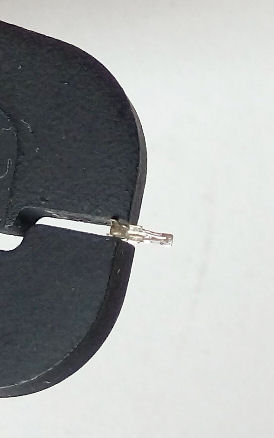
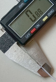
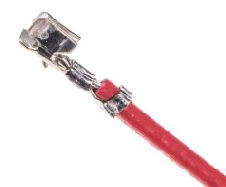
 Tolerance ±0.5mm
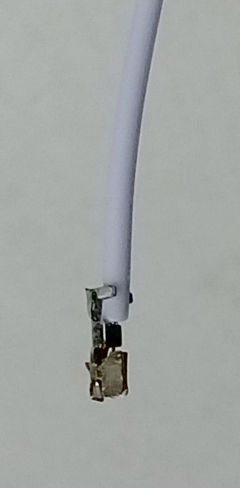
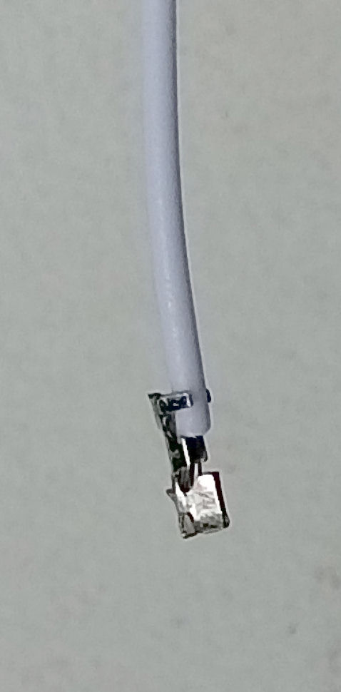
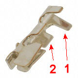 1mm pitch pin for crimping onto wire
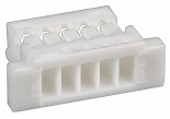 receptacle socket for housing the pins
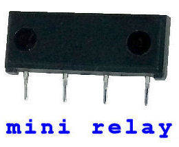
 Not only it is small in size, the tool for crimping this 1mm pin is also difficult to find. This tool is rare, hence it is also very expensive. The crimping tool for a