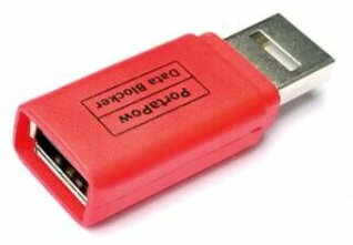
A dongle adaptor device to protect your mobile phone from hackers while charging your mobile phone in the public facilities. Stay safe while charging and protect your privacy from hackers. A must have data protection condom for your mobile phone.
Juice Jacking (Phone Hijacking)
A new method of mobile phone hacking known as Juice Jacking is used by hackers to hijack your phone. Mischievous virus program can infect your mobile phone via a public charging station.
Once your phone is plugged in the USB port, your phone will gets the infection. The malware infection will remains inside your mobile phone even when it has already been unplugged from the mischievous charging station. This allows the hackers to sniff on your online communication activities, your banking information, and sensitive data stored inside your phone.
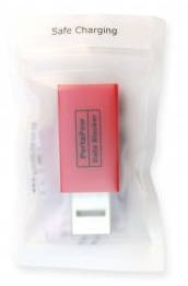
How to use this Data Blocker?
Charge your phone smartly.
Stay vigilant and protect your phone today by plugging in this Datablocker device between your mobile phone and a public charging station. This will prevent the infection to your phone and hence ensuring that you are safe from hacker.
If you are facing chip shortage issue, we can also help you to assess for design change or modification of the circuit to overcome IC chip shortage problem.
Microcontroller IC Chips
IC Chip Part Number
Qty Stock Available
PIC10F322T-I/OT
2
PIC16F18313-I/SN
27
PIC16F18325-I/ST
100
PIC16F18326-I/ST
1
PIC16F18344-I/SS
22
PIC16F18346-I/SS
21
PIC16F18456-I/SS
0
PIC24FJ256GA702
13
PIC16F1454
25
PIC16F1455
1
DSPIC33FJ128GP804-E/PT
7
DsPIC33FJ256GP506A-I/PT
12
PIC16F18323-E/SL
11
PIC12F1840-I/SN
3
PIC24FJ64GB002-I/SS
1
DSPIC30F2012
0
IC Chip Part Number
Qty Stock Available
PIC18F67J50 64 pins
PIC18F6722 64 pins
PIC24FJ256GB106 64 pins
Attiny44A SOIC-14
ATMEGA328PB-AU TQFP-32
ATMEGA32U4-AU TQFP-44
ATMEGA16U2 TQFP-32
dsPIC30F4013 DSP, 40 pins
DSPIC33FJ256GP506A-I/PT
DSPIC33FJ128GP804-I/PT
dsPIC30F2010
2
dsPIC30F3010
3
dsPIC30F3012
3
dsPIC30F3013
3
dsPIC30F4011
13
dsPIC30F4012
6
PIC12F675
3
PIC12F683
3
PIC16C745
6
PIC16LF84A
3
PIC16F628A
14
PIC16F684
3
PIC16F688
6
PIC16F88
10
PIC16F767
6
PIC18F1320
10
PIC16F84A
7
PIC16LF876A
8
PIC18F2220
3
PIC18F2320
6
PIC18F2331
3
PIC18F2410
3
PIC18F242
3
PIC18F2420
9
PIC18F2450
3
PIC18F248
3
PIC18F252
3
PIC18F2539
3
PIC18F258
9
PIC18LF1320
7
PIC18LF252
3
PIC18LF2520
1
PIC18LF2550
3
PIC16F648A
8
rfPIC12C509
4
PIC18F2553
6
PIC16C765
9
PIC16F74
3
PIC16F777
3
PIC16F874A
3
PIC16F876A
26
PIC16F886
20
PIC16F877A
42
PIC16LF877A
10
PIC18F2455
12
PIC18F2550
14
PIC18F4320
6
PIC18F4550
18
PIC18F4431
3
PIC18F4455
9
PIC18F452
6
PIC18F4520
9
PIC18F4525
3
PIC18F4539
6
PIC18F458
12
PIC18LF452
2
PIC18F4610
3
PIC18F4620
17
PIC18F4685
3
PIC18LF4520
5
PIC18LF4550
6
PIC18LF458
2
Other IC chips available in stock
IC Chip Part Number
Qty Stock Available
ENC28J60
7
MAX3232 SOIC16
LM5575
LM3224
LM2574M-ADJ
MAX668, MAX669, MCP1630
MAX4126, MAX4132, CA3130, ISL2827, ADR821
MAX4242
MAX4332
MCP111, MCP112
MCP9700
L6203
L298N
ADT7410TRZ
MMA7660FCT
PCF8574AT
MAX253
ADM3260ARSZ
MAX5400
MAX5401
MAX5402
MX536,LTC1968 (LTAFG), LTC1966 (LTTG)
AD71056ARZ, ADE7768ARZ, ADE7769ARZ
LM2588S-ADJ
LM2596S-5.0
LM2678S-5.0
LM2679S-5.0
ADG453, ADG452, ADG451, AS1500, AS1503
MCP3906A
ADE7753ARSZ
ADE7169ASTZF16
A1389LLHLT
A1324LLHLX
A1302KUA
A1321
ISL28276FBZ
ISL28218FBZ
LM336
Rclamp 0502A
LM258
MAX4562
MAX4574
TMP006
LM358DG, LMV358MMX, LM358DR
LM386M-1
HT9170D
INA126
MCP6N11
MCP73871
BMP085
TPS61200
TSC101BILT
CSD16322Q5C, CSD16325Q5C
A4915MLPTR-T
MTS2916A-HGC1
A4989 TSSOP-38
MCP8024T TQFP-4
L297D SOIC-20
DRV8805PWP HTSSOP-16
AD7781
25AA010A
TC77
TMP100
MAX3232
DIP package IC chips in stock
AD558JN 7 Mixed Signal 8bits DAC digital to analog converter
74LS245N 7 Digital Logic OCTAL BUS TRANSCEIVERS WITH 3-STATE OUTPUTS
AD574AJN, AD670JN, AD570JD Mixed Signal ADC, Analog to Digital converter
ADDAC80N, DAC0832 Mixed Signal DAC, Digital to Analog converter
AD834JQ Analog 500 MHz Four-Quadrant Multiplier
74LS259 Digital Logic 8-Bit Addressable Latches
74LS137 Digital Logic 3-LINE TO 8-LINE DECODERS/DEMULTIPLEXERS
WITH ADDRESS LATCHES
MA 339, 349, 03JB291 Analog Murata Japan gyro sensor
AD7523 Mixed Signal 8-bit multiplying DAC
TL16C550 2 Communication ASYNCHRONOUS COMMUNICATIONS ELEMENT, serial communication buffer
MAX233 4 Communication rs232 transceiver, without external capacitors
UC3906, bq2031 Lead-Acid Battery Charger
TCM680 9 Power Supply dual charge pump voltage converter Vout= +2Vin -2Vin
LM231, AD7742 Analog Voltage to Frequency Converter
LM2917 7 Analog Frequency to Voltage Converter
LBC180A 5 Communication RS485
MC145026 1 Communication data encoder decoder
LMC567 5 Tone Decoder
74LS00 2 Quad 2-Input NAND Gate
74LS04 9 Digital Logic Hex Inverting Gates
74LS08 5 Digital Logic Quad 2-Input AND Gates
74LS14 1 Digital Logic Hex Inverter with Schmitt Trigger Inputs
74LS15 5 Digital Logic TRIPLE 3-INPUT AND GATE
74LS32 2 Digital Logic Quad 2-Input OR Gate
74LS93 1 Digital Logic Decade and Binary Counters
74HCT123 3 Dual retriggerable monostable multivibrator with reset
74LS138 1 Digital Logic Decoder/Demultiplexer
74LS164 4 Digital Logic 8-Bit Serial In/Parallel Out Shift Register
74LS245 1 Digital Logic 3-STATE Octal Bus Transceiver
LBC179A 5 PCI/ISA Single Board Computer
LM311 2 Voltage comparator
DS1267 8 Dual Digital Potentiometer Chip
DS1869 6 3V Dallastat Electronic Digital Rheostat
DS275 2 Line-Powered RS-232 Transceiver Chip
MAX3100 16 SPI/Microwire-Compatible UART
MAX4623 2 Analog Switches 00175
MAX4700 2 Analog Switches 00176
MAX1062, MAX4584 Mixed Signal DAC digital to analog convertion, serial control video audio switch
MAX527 2 Mixed Signal Octal / 13-Bit Voltage-Output DAC with Parallel Interface
MAX731 2 Power Supply +5V/Adjustable Step-Up Current-Mode DC-DC Converters
We are a electronic specialist helping businesses to solve problems in the electronic industry.
Since year 2020 there has a global chip shortage trend. This is brought in by the Covid pandemic. Demand for electronics has massively increase. The semiconductor factories around the world has not been able to keep up with the global demand.
This chip shortage is projected to last till at least 2023. This boom in electronic demand is likely going to affect many electronic business. Sales will be affect and price of IC chips is likely having an upward pressure with the shortage.
Typically lead time of 3 months chip delivery has already increase to 12-24 months (as of 23rd Nov 2021). This long lead time is a big pressure to the electronic industry.
With panic buyers buying and hogging on to stocking up more electronics chip for their own use, or for their own profiting, this will even squeeze the market to an even higher demand. It is projected that this shortage situation is going to last at least till year 2023.
Preventive measure and preparation from PIC-CONTROL
PIC-CONTROL style of designing electronic product is by using parts/components that are easily available on the market. Pricing is typically better and we seldom will face IC chip or electronic components shortage.
Even when the IC chip ran out of stock, we can help our client to re-design their existing product so that it can retain its function through the use of alternative compatible IC chips. Our strength in electronic design.
We also provide services to help our client to research for IC chips alternative so that they are replace their existing components. Design adapter to replace them with compatible chips.
Solution to chip shortage problem
If you need expertise consultation to your current chip shortage issue, feel free to contact our sales engineer at PIC-CONTROL
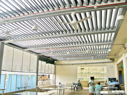
Automatic motorised Trellis system to shelter you from wet rain and hot sun shine, while you still get the fresh airy breeze. Louvered roof panel system installed with a rain sensor to automatically close the panel when it rains.
Installed Examples of Trellis Roof Shade System
Airy indoor open space using Trellis roof system.
The trellis roof can also be installed for indoor/outdoor balcony to create a spacious cool and relax area.
Feel the outdoor air breeze without too much hot and sunny sun shine. Nice natural lighting and cool open space.
This aluminum roofing system is designed to be light weight yet robust against strong wind and rain fall. Suitable for indoor and outdoor installation.
Trellis open close roof shade system for outdoor swimming pool.
Trellis roof system provides shades for your outdoor pool during a sunny day as well as raining days.
When the weather is good, the trellis can be open up to allow for shine and breeze through the open area.
Enjoy your pool with comfort.
Trellis shade roof system for indoor corridor.
This is an indoor trellis roof canopy structure installation for a corridor inside the house.
Allows outside natural light and air breeze to enter into the house.
Makes the house cooler, brighter while using less energy.
The rain sensing mode will automatically close up the trellis to ensure that your indoor environment is keep dry and clean.
Operating Instruction
The trellis roof control is simple to operate. One button to open and another button to close the trellis.
The trellis system also comes with a rain sensor. When rain is detected, the trellis shelter can automatic close up itself so that your corridor stays dry.
An optional external buzzer can be install for auditory feedback to the user.
Opening Closing Trellis
A single push and release on the open button, the trellis will open to its preset half opening position. This preset position can be adjusted form the blue color POT on the circuit board. Another push and release will fully open the trellis.
A single push and release to the close button will fully close the trellis.
For controlling of the trellis opening to your preference, you can simply push and hold the button, to open/close the panel, and release the button when the panel reaches the position that you want.
Rain Detection
Rain detection mode can be activated to automatic control the trellis when it rains. The trellis will automatically be closed and do not allow to be open until the water gets dry out.
To open the trellis manually while the trellis is still wet, you have to switch off the rain detection mode first.
User can select this rain detection mode via a switch. The rain sensor mode indicator will get light when this mode is selected. When it is in OFF mode, the indicator will be turned off. This indicator will blink when rain is detected. If the rain mode is switched ON, the lighted indicator will starts to blink when rain is detected. Even if the rain mode is switched OFF, the indicator light will still blink when rain is detected, just that the blinking rate is slower.
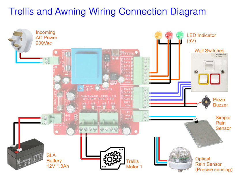
System Connection Wiring
This section shows how
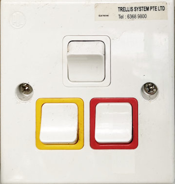
Wall switch to open/close the Trellis and to set for rain sensing.Wiring Connection Diagram (for single bay Trellis installation)
Low cost rain sensor can be connected to this board to detect raining event. If the rain sensing mode is active, the trellis will automatically close itself to shelter away from the water. If you like the trellis to reacts faster to the rain, you can choose to install optical rain sensor instead. It is more precise in the rain sensing and can react faster to raining and rain stopping. You can order optical rain sensor from PIC-CONTROL.
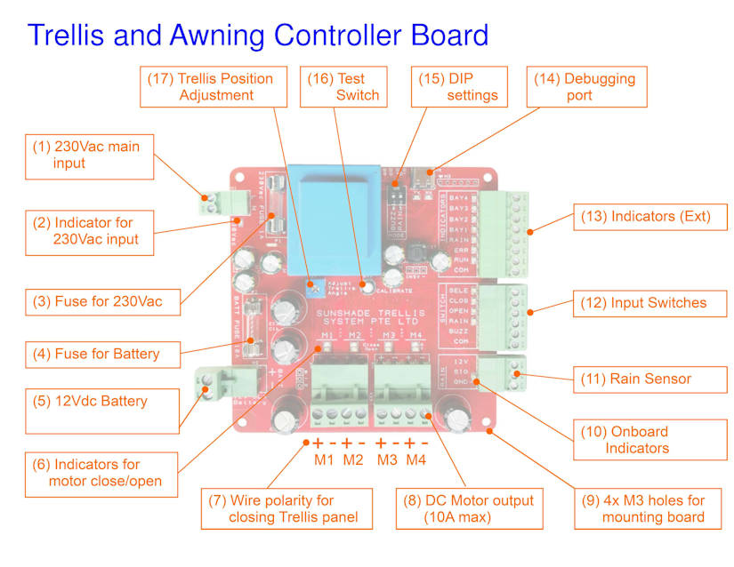
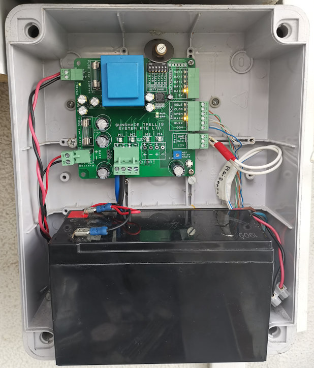
Trellis Roof Controller Board
This is the main controller board for the trellis automated roofing system. It is the main board for driving the geared DC motor of the trellis system. Design to drive geared DC motor with a rating at about 1A (when it moves), and a stall current at about 8A to 10A.
The following is the description of the controller board.
Electronic controller circuit board for Trellis Roof Shade System.
(01) 230Vac mains incoming power input
230Vac is required for charging of the SLA battery.
(02) Indicator for 230Vac incoming power
Green indicator will gets lighted up when there is power coming from the 230Vac input.
(03) Fuse for 230Vac
Fuse of 1A is recommended for protection from the 230Vac incoming mains power source.
(04) Fuse for Battery
Fuse of 10A to 15A is recommended for protection from the battery.
(05) SLA Battery
Sealed Lead Acid Battery. Recommending 12V 1.3Ah capacity battery (97 x 43 x 51mm). Larger size 12V 7Ah SLA battery (152 x 66 x 94mm) can also be use.
This battery is used for driving the DC motor of the Trellis.
(06) Indicators for Trellis motor
When the controller is driving the Trellis motor to close, Green indicator will gets lighted up. For opening of the Trellis, Yellow indicator will gets lighted up.
(07) Motor Wire polarity (closing the Trellis)
Motor wire polarity for closing the Trellis panel is motor positive terminal on the left (pin 1), and negative terminal on the right (pin 2). Apply this polarity should activate the motor to close the Trellis.
(08) DC Motor output
DC motor output is design for driving a DC motor up to a maximum current of 10A. Typical operating current is about 1A, and can spike up to 8A to 10A when the motor is in a stalled position.
(09) Mounting Holes M3 x 4
Mounting holes available at the 4 corner of the board. Design for M3 screw mounting. Distances between the mounting holes are about 91.5mm apart.
(10) Onboard indicators
Indicators onboard for technician monitoring and troubleshooting use.
(11) Rain Sensor interface
This interface allows a simple resistivity rain sensor to be connected via two wire, signal and ground pins.
It can also connect to a more sensitive and responsive optical rain sensor for a better user experience.
(12) User switches and buzzer interface
Switch buttons for user to control and beep sounder feedback.
Open Trellis
Close Trellis
Rain Sensing Mode
Bay Select
Beep Sounder
(13) External Indicators
User indicators for operation and monitoring.
RUN
ERROR
RAINING
BAY 1 (available in 4 bay controller board)
BAY 2 (available in 4 bay controller board)
BAY 3 (available in 4 bay controller board)
BAY 4 (available in 4 bay controller board)
(14) Debugging port
USB debugging port for monitoring purpose. It is a virtual serial communication port with the following settings,
baud-rate 115200bps
No Parity
8 Data bits
1 Stop bits
(15) DIP switches
— Not available —
(16) Test switch
— Not available —
(17) Trellis position adjustment POT
When the open button is pressed for the first time from the Trellis panel closed position, the panel will open to the half open panel position. This half open panel position can be adjusted to your preference by adjusting this (17) Trellis position adjustment POT.
Battery Power and Protection System
The whole system is powered by a 12Vdc SLA Battery (Sealed Lead Acid Battery). A battery capacity of 1.3Ah is enough for typical operation.
The charging of this SLA battery is supplied via the 230Vac power input. This power do not supply power to the trellis. It is only used for charging the connected SLA battery. If the SLA battery is not connected, the system will not be able to operate correctly. This 230Vac do not have enough power to drive the trellis motor. A 1.3Ah SLA battery capacity can drive the Trellis for about 30min to 60min without any charging. It is ok to install a high capacity battery if want the system to operate longer when AC power is not available (A power blackout scenario).
A battery monitoring is designed onto the system. If the voltage level of the battery falls below a healthy level, the ERROR indicator will start blinking. When this happens, the controller will only allow user to close but not open the trellis. This is to protect the battery from over draining itself, and to conserve the energy so that it can have enough power to close up the trellis when it detect rain. If the blinking appears, you can simply wait for a while. The battery will be charged up, and allow for normal operation again. This can happen when someone is operating the trellis for a continuous period of 30min or more, or if the battery becomes faulty after long use.
It is recommended to replace the battery every 4-5 years of operation.
The system ERROR indicator will appeared to blink faster if the battery is suspected to be faulty. If this happens, leave the system alone for 24 hours. If the ERROR indicator blinking persist, please contact for technical support. It could likely be cause by the following…
No incoming 230Vac power supply.
Faulty charging circuit.
Battery is faulty (normal wear & tear).
The technician will diagnose and help you rectify the problem.
Technical Specification
Board power consumption is about 1W, up to 12W max
AC Power Input: 230Vac 0.1A (for battery charging purpose)
DC Power Input: Sealed Lead Acid Battery SLA 12Vdc 1.3Ahr (for motor operation)
Output driver support geared DC motor of 12Vdc 1A (10A max rating)
Support low cost resistive, or high precision optical rain sensor.
Cable current capacity for the Battery and Motor can operate peak at about 10A. Cable gauge size of AWG16 is recommended.
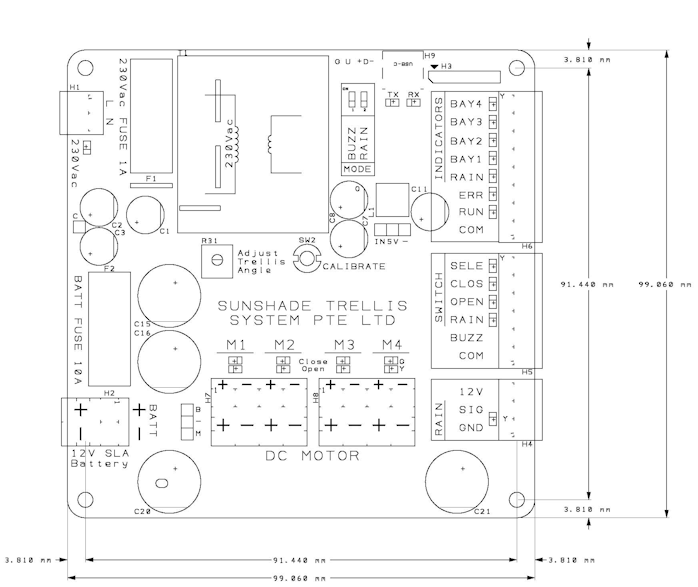
Trellis Controller Board Dimension
The physical board size is about 99 x 99 x 36mm.
Propose M3 mounting hole position is 91.5 x 91.5mm. (mounting hole size is 3.2mm, suitable for M3 size screws)
Trellis Controller Board Dimension
The weight of this board is about 350g.
Deployed Site Installation
This is a installation for a single bay Trellis controller.
The board requires a 12Vdc Seal Lead Acid battery to function and for powering up the motor. Battery as small as 12Vdc 1.2Ahr battery can be use. (can continuously operates for about 45 minutes without the charging 230Vac power mains)
Trellis controller installation
Troubleshooting
Symptom Observation
Possible Cause
Error Buzz Tone
This is the most common feedback from a user. A low sound tone sounded when the switch is pressed. This can occurred when the Trellis is not allowed to be opened when it is raining and the rain sensing function is enabled.
Error buzz tone will also sound when you are trying to open the Trellis when the battery charge is low or the battery is faulty.
ERROR Indicator Blinking (slow).
Battery voltage is low. Low in charge. This may also happen if 230Vac is not connected, or the charging circuit is faulty. If the system has been operating open/close action for long period of time, this may happen too. To conserve energy during this period, the Trellis can be close but cannot be open. You can wait for 24 hrs for the battery to be charged up before you can operate it normal again.
ERROR Indicator Blinking (fast).
Battery voltage is super low. Battery probably needs a replacement. Please call for technical support.
Cannot open Trellis.
Check if ERROR indicator is not blinking. If it is blinking, read up the possible cause above. You can
If the Rain indicator is blinking. The Trellis will not allow to be open, if battery level is low. You can wait for 24 hrs for the battery to be charged up, and attempt to open again. The trellis will also not open if the rain sensing is enabled and water is detected. You can disable the rain sensing function, and open the Trellis.
If no indicator is blinking and the Trellis cannot be open, please call for technical support.
Cannot close Trellis.
Please call for technical support.
Trellis do not automatically close when it rains.
Please ensure that the rain sensing mode is enable. If rain sensing mode is enabled and the Trellis do not close automatically when it rains, please call for technical support.
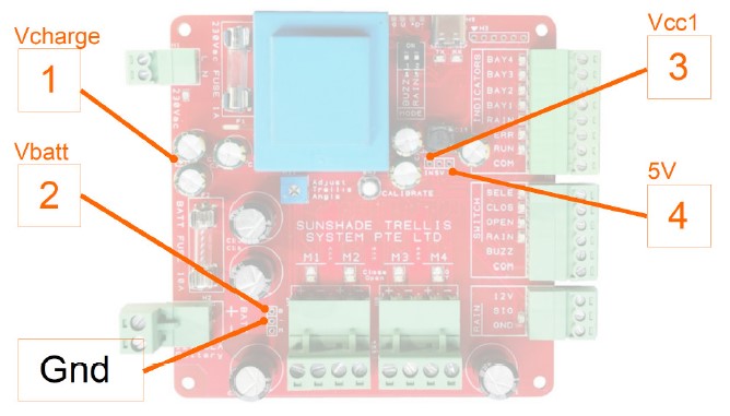
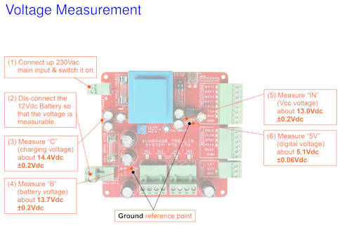
Board Voltage Measurement Test
When doing this measurement to test if the board has all the voltage at the correct level, the battery has to be disconnected, and the AC main power input has to be switched on.
With reference to the Gnd pin, the voltage measured from the board labelled no. 1 to 4 should be as follows,
Vcharge = 14.4V ±0.2V (battery charging voltage)
Vbatt = 13.7V ±0.2V (battery voltage)
Vcc = 13V ±0.2V (unregulated supply to the circuit)
5V = 5V ±0.06V (regulated supply to the circuit)
Checking voltage measurement point on the board.
Fast measurement tips:
The voltage different between point 1 and 2, point 2 and 3 is about 0.7V differences.
This section shows how to setup a tool for sniffing of Bluetooth protocol and learn about the Bluetooth devices through reverse engineering of the Bluetooth protocol.
Inside contains the *.hex file for the nRF Bluetooth board. This file is a firmware to program the hardware board and turns it into a Bluetooth sniffer tools for sniffing Bluetooth communication.
It also contain some script program plugin for Wireshark software to work seamlessly with the nRF sniffer hardware. The files is all inside the folder “extcap” to be copy later into wireshark folder.
Turn nRF52 DK into a Bluetooth Sniffer board
The board I am using is nRF52 DK board. So prepare the hex file “sniffer_pca10056_xxxxxxx.hex”. Connect the board to the computer.
Once you are in the Programmer program, (top left corner) select the device that shows “PCA10040”. This the board model of the nRF52 DK board that we are using.
You should see success message in the Log messages below the application. After a few seconds, the connection will be ready, and you will notice that the <Read> button on the right column of the application is enabled.
Now click on the button that says “Add HEX file”. Browse and select the correct hex file for this PCA10040 board.
Once you choose the hex file, you will be back onto the main window. The file memory layout display will be refresh with a orange block. The button for the <Erase & write> will be enabled too. Click this button to program the PCA10040 board with this sniffer firmware.
The <Read> button will be grayed off during this firmware programming period. When the firmware finish flashing, you will also notice the button is enabled back.
Now your board has become a Bluetooth data sniffer.
After installation, go to the menu -> Help ->About Wireshark. Go to the tab Folders. Double click on the link next to the name Personal Extcap path. This will open up the folder from your Window explorer.
From the files that you have downloaded earlier, copy all the files from the folder “extcap” onto this new directory from Wireshark program.
Press Ctrl+Esc and type in “cmd” from the search field. You will the Command Prompt app appear on the menu. Right click it and click on the “Run as administrator“. This is important to give administrator right when you key in the command in the following section.
Go to the directory “extcap”. Key in the following command in the command prompt.
pip3 install -r requirements.txt
Once installed, key in the following command to check if the installation is correct and is working.
nrf_sniffer_ble.bat --extcap-interfaces
C:\Program Files\Wireshark\extcap>nrf_sniffer_ble.bat --extcap-interfaces

extcap {version=3.0.0}{display=nRF Sniffer for Bluetooth LE}{help=https://www.nordicsemi.com/Software-and-Tools/Development-Tools/nRF-Sniffer-for-Bluetooth-LE}
interface {value=COM16}{display=nRF Sniffer for Bluetooth LE COM16}
control {number=0}{type=selector}{display=Device}{tooltip=Device list}
control {number=1}{type=string}{display=Passkey / OOB key}{tooltip=6 digit temporary key or 16 byte Out-of-band (OOB) key in hexadecimal starting with '0x', big endian format. If the entered key is shorter than 16 bytes, it will be zero-padded in front'}{validation=\b^(([0-9]{6})|(0x[0-9a-fA-F]{1,32}))$\b}
control {number=2}{type=string}{display=Adv Hop}{default=37,38,39}{tooltip=Advertising channel hop sequence. Change the order in which the siffer switches advertising channels. Valid channels are 37, 38 and 39 separated by comma.}{validation=^\s*((37|38|39)\s*,\s*){0,2}(37|38|39){1}\s*$}{required=true}
control {number=3}{type=button}{role=help}{display=Help}{tooltip=Access user guide (launches browser)}
control {number=4}{type=button}{role=restore}{display=Defaults}{tooltip=Resets the user interface and clears the log file}
control {number=5}{type=button}{role=logger}{display=Log}{tooltip=Log per interface}
value {control=0}{value= }{display=All advertising devices}{default=true}
Enable the nRF Sniffer capture tool in Wireshark
Refresh the interfaces in Wireshark, go to Capture -> Refresh Interfaces (or pressing F5). You should see that nRF Sniffer is displayed as one of the interfaces on the start page.
Go to Capture -> Options, to untick other communication interface that is not relating to the Bluetooth. We only want to see communication data from Bluetooth. If all interfaces are enabled, the data captured will be massive and difficult to find Bluetooth data.
Select View -> Interface Toolbars > nRF Sniffer for Bluetooth LE, to enable the sniffer interface menu bar to appear below the file menu in the Wireshark program.
Adding Wireshark profile
Go to Help -> About Wireshark. Select the Folders tab. Go to the link Personal configuration, and double click on the link to open up the folder. There is this profile folder. Open up this profile folder.
Copy the folder “…\Profile_nRF_Sniffer_Bluetooth_LE\” to this into this profile folder. Your directory path should look like the following, “C:\Users\xxx\AppData\Roaming\Wireshark\profiles\Profile_nRF_Sniffer_Bluetooth_LE\“
Go to the menu select Edit > Configuration Profiles. Select the new “Profile_nRF_Sniffer_Bluetooth_LE” profile. This is the configuration of how the data display is setup for easy viewing.
Start Sniffing
Press Ctrl+E or go to menu Capture -> Start to start capturing the Bluetooth packets. You can select the exact Bluetooth device that you want to listen/sniff.
I have two nRF52840-DK boards, with one programmed as a Peripheral which advertise (broadcast), and another one programmed as a Central to do scanning (searching).
Blinky Central (examples->ble_central->ble_app_blinky_c)
To keep learning simple, we evaluate step by step. We switch off the Blinky Central module.
Advertising Packet Transmitted from Blinky
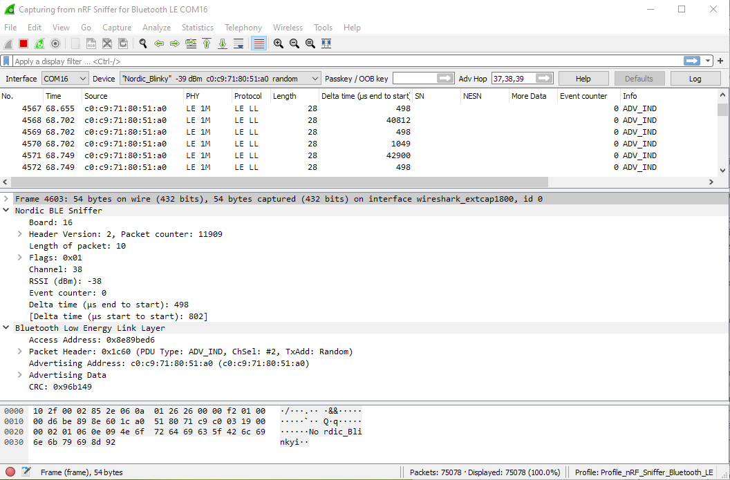
Blinky being a peripheral will boardcast advertising packet to allow other Bluetooth device to locate it. We will study what is inside an advertise packet of this peripheral from Nordic Bluetooth Blinky example.
Packet captured from the Blinky Peripheral
The period of blinky sending advertising packet is about 1msec
From this packet, I can see two part of data. One is from the sniffer itself, displaying the channel that it is sniffing, the RSSI (signal strength).
The other is the BLE Link Layer data sent from the peripheral displaying the address, and its peripheral device name.
Received Signal Strength Indicator RSSI: -17dBm (Very Good Signal Strength) RSSI: -35dBm (Good) RSSI: -50dBm (Ok) RSSI: -70dBm (Poor)
The delta time (end to start): 498us is the time delay of the end of the previous data packet to the start of the current packet. It is the idling time between packet data transmission.
The delta time (start to start): 802us is the time delay of the start of the previous data packet to the start of the current packet. It is the time period of the transmission. (transmission frequency of the packet)
Packet Information from the Sniffer
Is probably added information from the sniffer itself. It tells us about the information of the packet. Eg. Timing, RSSI, packet counting, data direction, transmitting channel, etc…
PDU Type: ADV_IND means Undirected Advertising. To broadcast itself to a Bluetooth Central device for a connection.
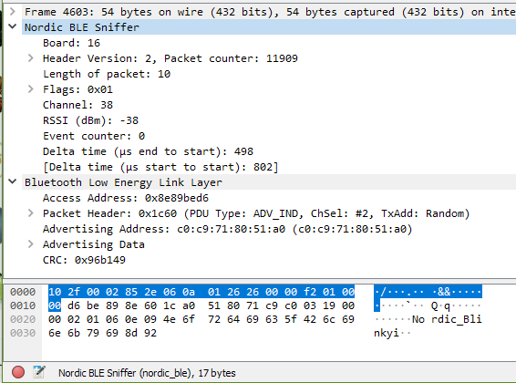
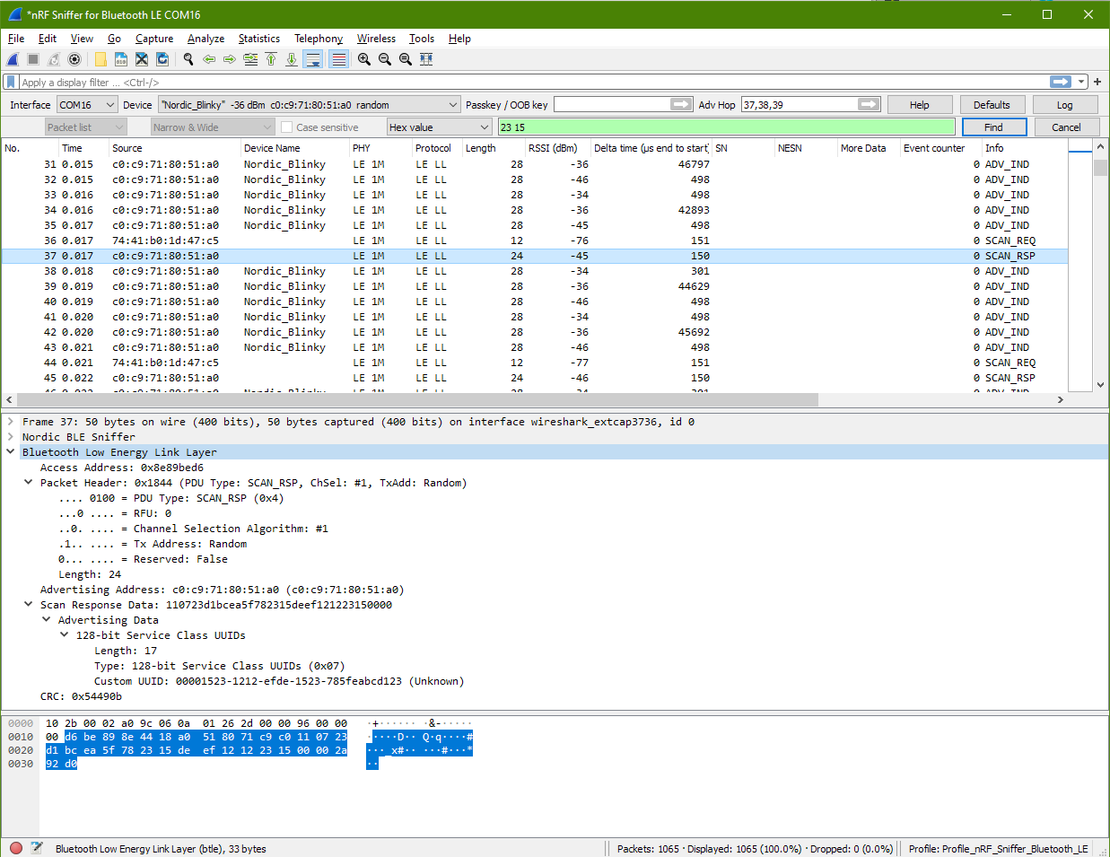
Scan Response Detected from Blinky
After looking at the the advertising packet from Blinky, I also notice Blinky transmitting out another packet.
Scan Request Packet to Blinky Peripheral
From the packet no. 37, I can see that Blinkly is transmitting a packet. Looking at the end of the “Info” column, I see SCAN_RSP. This is a scan response from Blinky
Looking at a packet before this packet, I can see packet no.36 (source=74:41b0:1d:47:c5) sending out a SCAN_REQ scan request packet. It is other Bluetooth device sending a scan request to Blinky. You can see from the RSSI of -76dBm that this device is quite a distance away from my Blinky device.
As the front data are from Nordic BLE Sniffer, we will skip that and proceed to look at only the data from the Bluetooth Low Energy Link Layer only.
The Access Address (AA) is the same as the previous evaluation that we did. After some research, it is found that this Access Address is standardise to 0x8E89BED6. It is a preamble signal to identify the radio communication on the physical link.
Now going back to look at the Scan Response packet.
d6 be 89 8e 44 18 a0 51 80 71 c9 c0 11 07 23 d1
bc ea 5f 78 23 15 de ef 12 12 23 15 00 00 2a 92
d0


d6 be 89 8e | Access Address: 0x8e89bed6

44 18       | Packet Header: PDU Type: SCAN_RSP
              44 |
                 | b7 Reserved: False
                 | b6 Tx Address: Random (1)
                 | b5 Channel Selection Algorithm: #1 (0)
                 | b4 RFU: 0
                 | b3-b0 PDU Type: SCAN_RSP (0b0100)
              18 | Length: 24 (Advertising Address (6bytes) + Scan Response Data (18bytes))

a0 51 80 71 c9 c0 | Advertising Address: C0:C9:71:80:51:A0

11 07 23 d1 bc ea 5f 78 23 15 de ef 12 12 23 15 00 00
                  | Scan Response Data (advertising data)
                    11 | Length: 17
                    07 | Type: 128-bit Service Class UUIDs (0x07)
                    23 d1 bc ea 5f 78 23 15 de ef 12 12 23 15 00 00
                       | Custom UUID: 00001523-1212-efde-1523-785feabcd123

2a 92 d0          | CRC: 0x54490b
The scan response returns the data type 128-bit Service Class. This is the long form UUID 00001523-1212-efde-1523-785feabcd123, which identify the service provided by this Bluetooth peripheral.
How CRC is computed?
CRC is 0x54490b base on the hex data of 2a 92 do
Probing a Connection to Blinky
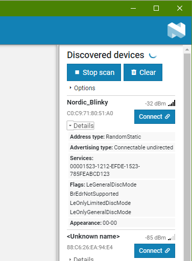
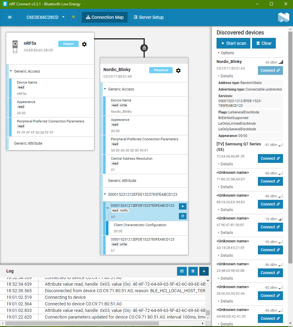
The following uses nRF Connect to connect to the Blinky board.
Connected to Blinky
This screen shot shows what data will be read to this nRF software when the Blinky gets connected.
This data will be verified with the data communication after the module is connected. We will dive into the data packet details later. We should be able to see all the data as reflected in this nRF Bluetooth app.
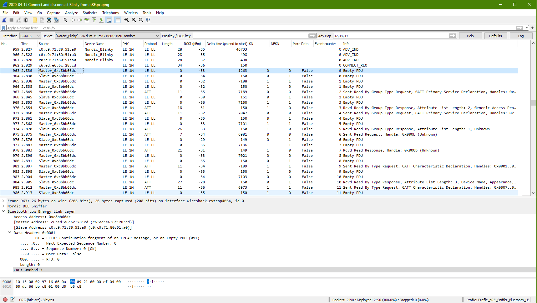
The nRF software uses nRF52 Dongle as the bluetooth device to scan for Blinky device. The nRF52 Dongle MAC address is C6:ED:E6:6C:28:CD
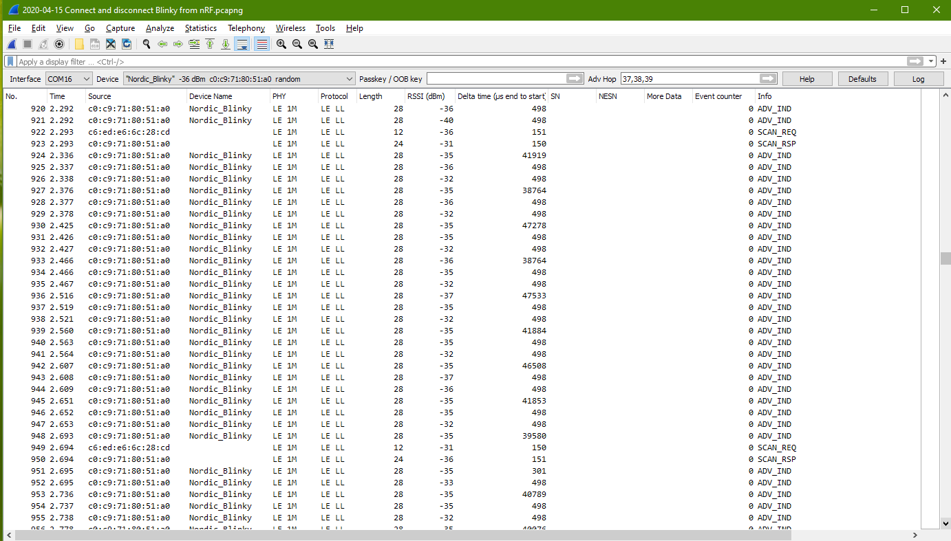
Packet Capture to show nRF scanning for Blinky board.
This packets shows Blinky sending advertise packets to broadcast to other bluetooth. It also shows that the nRF software is sending out scan request to check out the blinky device which was advertising itself frequently. The scan request message from nRF to the Blinky is observed to be about 400ms apart. About 2 scan request message per second.
Blinky responsed to the scan request sending back more detail about itself.
Packet Capture to show nRF scan request connection to Blinky
The nRF apps get to connect with Blinky about 135ms after its scan request.
This connection started at packet no. 962, with the nRF Connect connects to the Blinky.
After the connection, the source and destination MAC address seems to be no longer appear.
There will be no more advertising from the Blinky.
Communication is only between nRF apps (Master) and the Blinky (Slave). Period of communication is about 5-10msec.
PDU is no longer indicated after the connection. PDU is for higher level BLE device discovery and connection process. Type of PDU available – ADV_IND – ADV_DIRECT_IND – ADV_NONCONN_IND – SCAN_REQ – SCAN_RSP – CONNECT_REQ – ADV_SCAN_IND
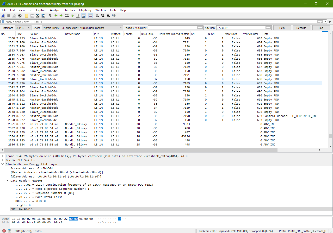
Packet Capture to show nRF disconnect from Blinky
When nRF apps disconnect from the Blinky, the Control Opcode: LL_TERMINATE_IND can be observed. Slave response, and shortly after return to its disconnected state and begin to advertise again. Advertise period is about 10msec.
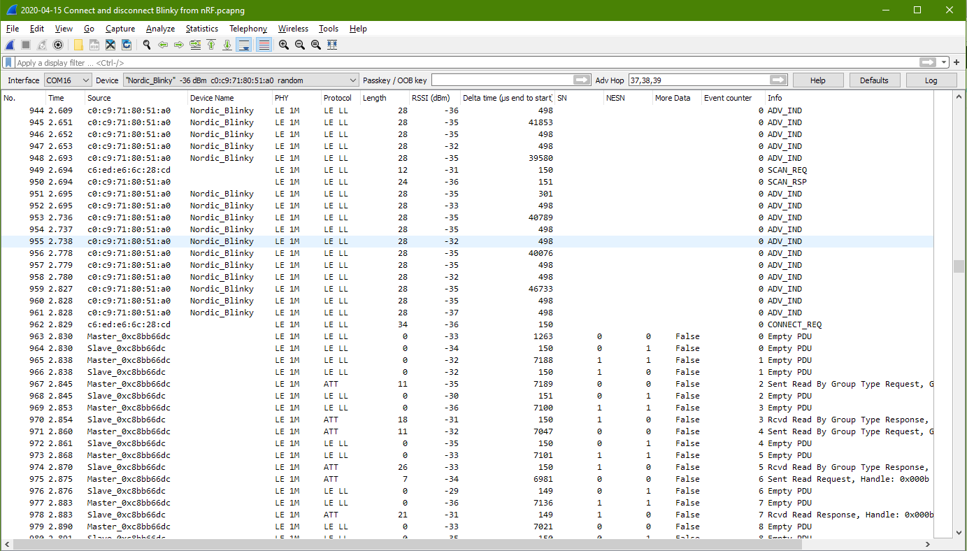
Service Discovery packets after connected
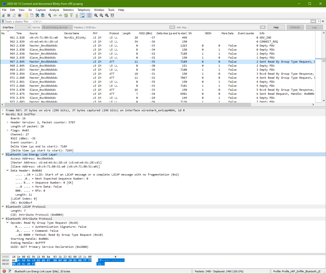
Shortly after the Blinky gets a request to be connected at packet 962, the GATT discovery starts popping out from packet 967 (time 2.845sec) to packet 1036 (time 3.100sec)
Packet 967 from master has a starting handle of 0x0001 to 0xffff, seems to be master asking for services that within these range from the slave.
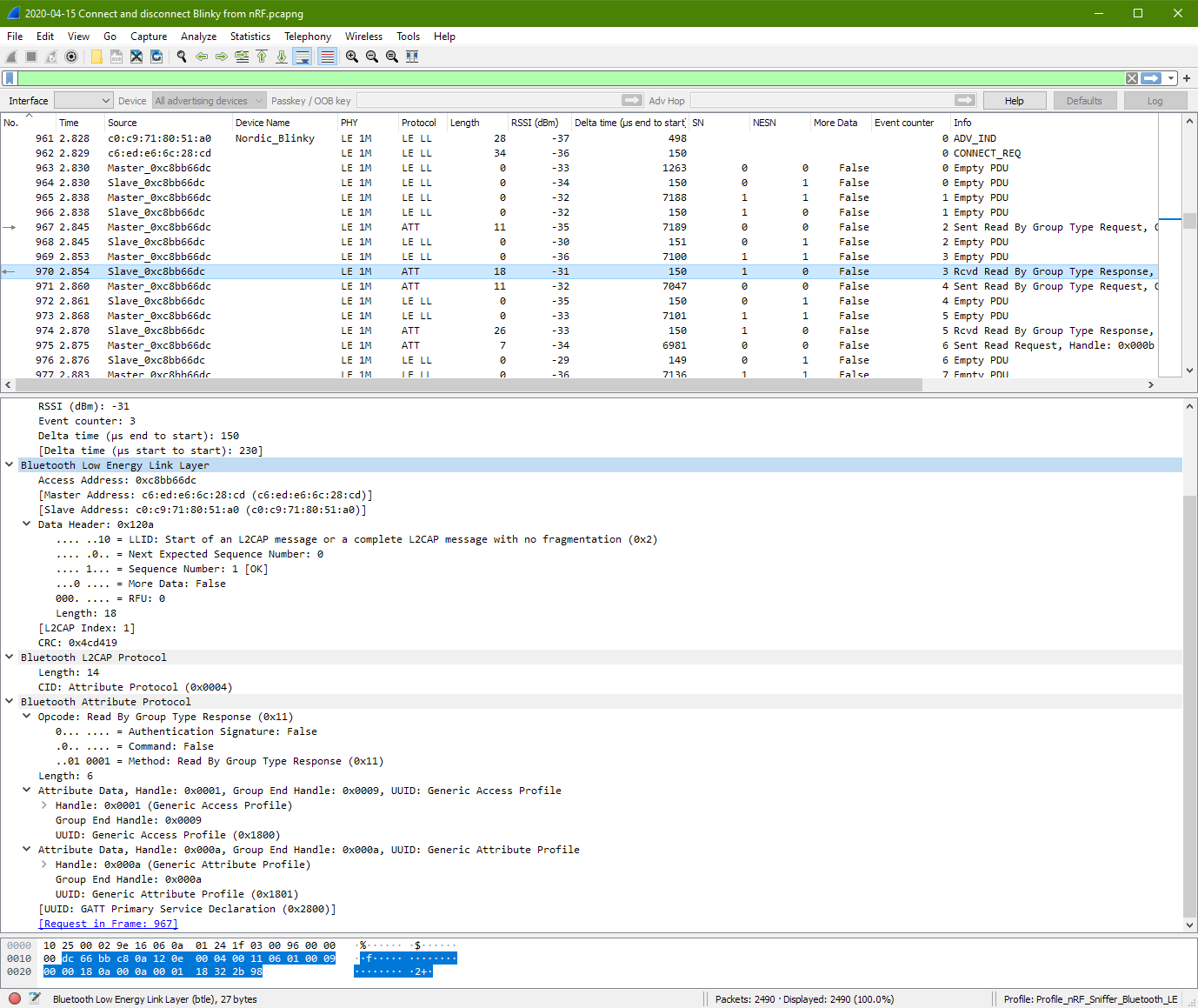
Packet 970 from slave response with 2 services. One at handle 0x0001, the other at handle 0x000a.
Packet 971 packet from master is almost the same as packet 967. Only the starting handle is different thsi time. It is at 0x000b. This is perhaps master is probing from the slave whether if there are more services from the handle range 0x000b to 0xffff.
The slave response at packet 974 with a handle at 0x000b (which is unknown) with a UUID of 23d1bcea5f782315deef121223150000.
Handle 0x000b eventually stop at packet 978.
The master send a packet no. 981 for a range from starting handle: 0x0001 to 0x0009. Seems that the master understand the messages from slave and starts to adjust its range. It is note that this master has change its read request from “Read By Group Type Request” to “Read By Type Request”.
At packet no. 984, the slave returns even more information. Information about the Generic Access service block.
The master continue to probe at packet 985. Slave packet 988 returns the remain information from the Generic Access service block.
Packet no. 989 to 1004 is master probing deeper (Read Request) from the Generic Access service for more detailed information.
The master starts from “Read By Group Request” (packet 967 to 974) to “Read by Type Request” (packet 981 to 988), and finally “Read Request” (packet 989 to 1004).
These are the GAP profile from what I can see on the Wireshark screen.
Then the master process to Find Information from packet 1007 to 1029. These are the GATT characteristic as displayed.
The last 2 packets (packet 1033, 1036) are Read Request from GAP Profile’s Device Name.
Summary of the connection.
The connection happens at packet no. 962 (time: 2.829sec), and ends at packet no. 2350 (time: 8.027sec).
Within the connection period from packet no. 962 to 2350, the GATT protocol appear. GATT communication (ATT L2CAP protocol) start on packet no. 967 (2.845sec) and ends at packet no. 1036 (3.1sec).
The GATT packets are filtered out from Wireshark. It is noted that it took a total of 28 packets (ATT L2CAP protocol), to complete exposing Blinky’s GATT services to the master device.
Average RSSI maintain good at around –35dBm.
Generic Access Service information can be detected at packet no. 970
Generic Attribute Service information can be detected at packet no. 970
Going through the connected packets one at a time.
We are more or less familiar with how data are presented in the bytes level. We will now focus more on the data information instead of the bytes level.
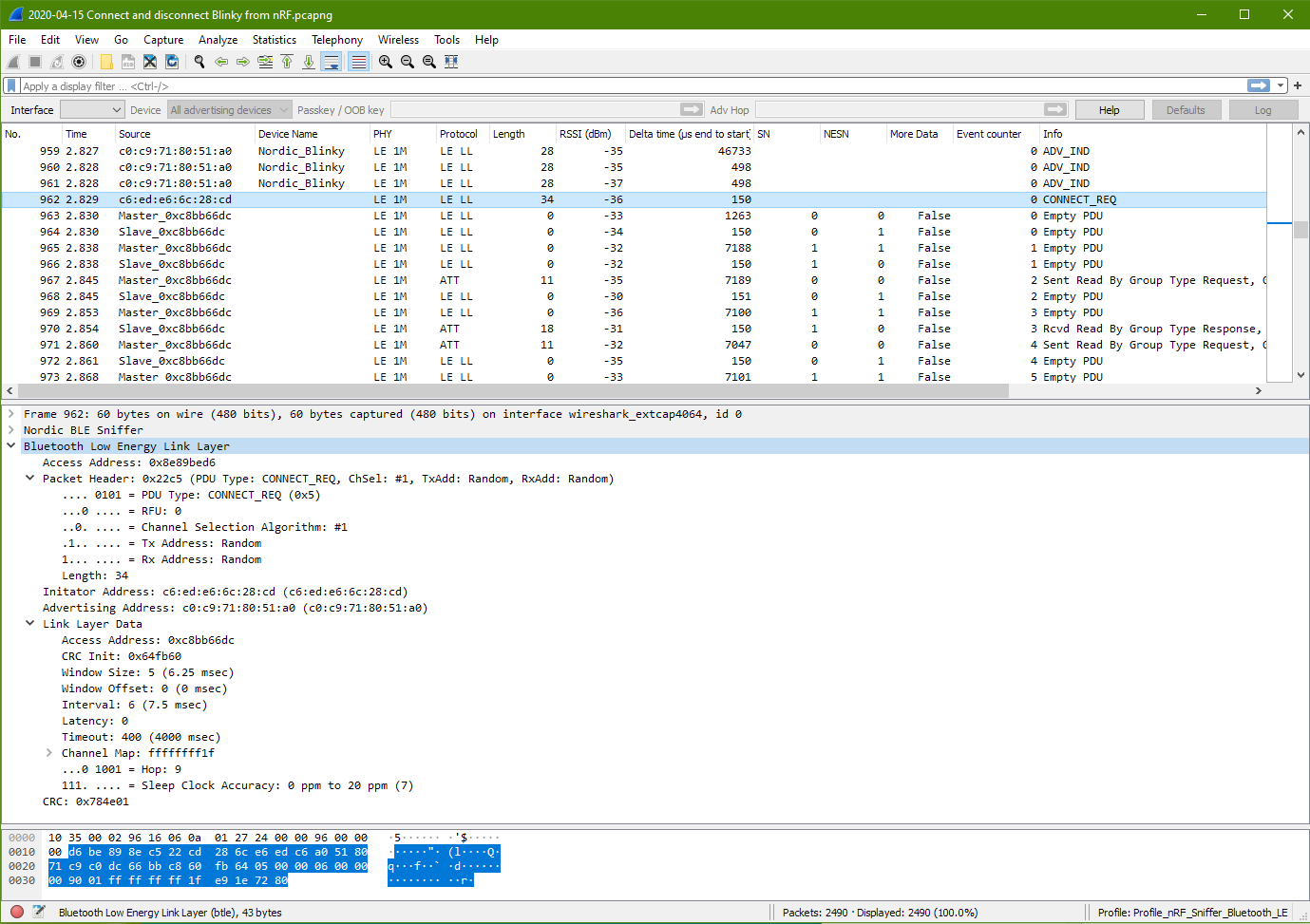
Connect Request Packet
This packet data and the usual data structure to take note. The Bluetooth Low Energy Link Layer packet is always consist of size part.
Bluetooth Low Energy Link Layer
Access Address (preamble data)
Packet Header (what this packet is about)
Initator Address (who request the connection)
Advertising Address (the peripheral device to accept this connection)
Link Layer Data (the data)
CRC (data integrity checking)
Access Address: 0x8e89bed6 (the usual fixed preamble data at the beginning of the BLE data packet)
Packet Header
PDU Type: Connect_REQ (0x5) Data Length: 34 (address + link layer data)
Initator Address: c6:ed:e6:6c:28:cd
Advertising Address: c0:c9:71:80:51:a0
Link Layer Data
An new Access Address is assigned as 0xc8bb66dc CRC Init: 0x64fb60 Window Size: 5 (6.25msec) Window Offset: 0 (0msec) Interval: 6 (7.5msec) Latency: 0 Timeout: 400 (4000msec) Channel Map: ff ff ff ff 1f (default RF Ch 0, 12, 39 for advertising) Hop: 9 Sleep Clock Accuracy: 0 to 20ppm (7)
CRC: 0x784e01
Hop: 9 means to hop 9 channel away from the current channel. New channel = (curr_channel + hop) mod 37
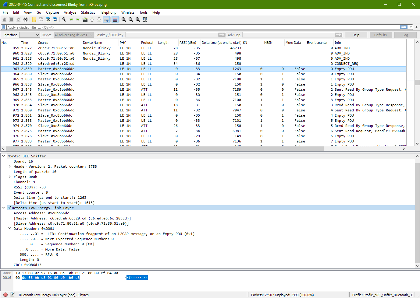
Connected (Master packet 963)
10 13 00 02 97 16 06 0a 0b 09 21 00 00 ef 04 00
00 dc 66 bb c8 01 00 d0 b6 c8

10 13 00 02 97 16 06 0a 0b 09 21 00 00 ef 04 00 00 | Nordic BLE Sniffer

dc 66 bb c8 01 00 d0 b6 c8 | Bluetooth Low Energy Link Layer
It is noted that the communication Channel is 9. The previous channel during the advertising and connection packet was at Ch 39. This current channel 9 could be the result of the channel hopping.
Access Address: 0xc8bb66dc The access address is different from the previous one. This same access address is used through out the connection period.
It is noted that the Master & Slave Address being keep tracked. However the address is no where to be found in the packet. This means that the addresses should be tracked by the Wireshark program, probably through the Access Address 0xc8bb66dc
There is only the data header with no data. The data header format has changed. It is different from the format before the connection. – LLID: L2CAP message – Next Expected Sequence Number: 0 – Sequence Number: 0 [OK] – More Data: False – RFU: 0 – Length: 0
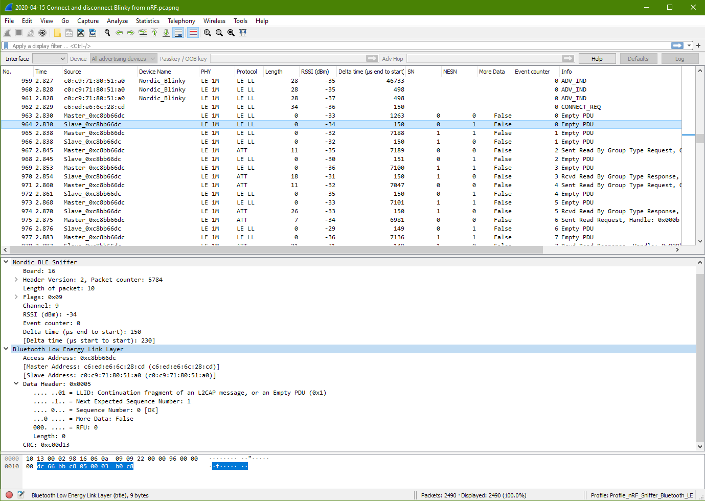
Connected (Slave packet 964)
This slave packet looks very similar from the master packet. The Access Address is the same. The next expected sequence number is 1.
It is observed that both the Next Expected Sequence Number and the Sequence Number keep rotating in sequence 00 01 11 10 ….. It is a sequence number using 2 bits.
More Data could mean if there are more following packets coming which is related to this current packet.
It is also observed that for every pair of master/slave packet, the channel hop by 9 ch. Ch9, 18, 27, 36, 8, 17, 26, 35, 7, ……. The channel keep hopping. There is also an event counter on the sniffer which will increment for each pair of master/s;ave communication.
The delta delay between the Master and Slave pair is about 150us gap, 230us packet period.
The delta delay between the Slave and Master of the next pair is about 7190us gap, 7270us packet period.
This packet seems to be sending a command to start the GATT.
The slave seems to reply nothing (packet 968) like the previous slave response. Seems more like an acknowledge purpose to the master device.
This is followed by Master sending nothing (Master packet 969).
It is noted that packet 968 and 969 doing nothing is labelled as the LE LL protocol (Low Energy Link Layer).
The attribute data packet 967 and 970 are labelled as ATT L2CAP (Logical link control and adaptation protocol).
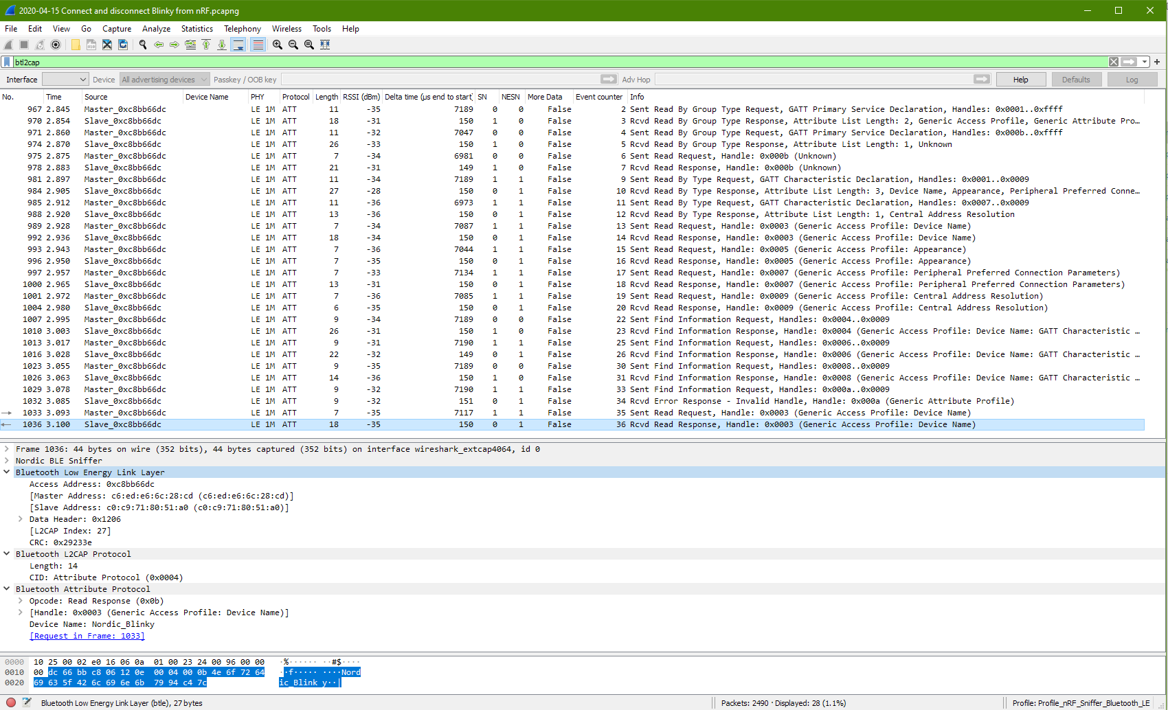
First Attribute Response Protocol (Slave packet 970)
This is noted in the sniffer wireshark that this packet 970 is the response that is requested from packet 967 (GATT Service request 0x2800). The tools is keeping track of the messages.
More data can be seen by this slave response. The slave is returning 2 groups of attribute data.
UUID: Generic Access Profile (0x1800)
Handle ID (0x0001)
End Handle ID (0x0009)
UUID: Generic Attribute Profile (0x1801)
Handle ID (0x000a)
End Handle ID (0x000a)
Other observation on the bluetooth communication
In this observation on the bluetooth pad lock, it was noted that during the CONNECT_REQ, the Channel Map turns out to be FF FF FF 07 00. This is very different from the previous observation which is FF FF FF FF 1F. In the previous observation, all the channels are active except for the advertising channel 37, 38, 39.
Base on this difference and some research from online, I would assume that the purpose of this Channel Map is probably to map out the available channel for use. In the previous observation, except for the 3x advertising channel, all the channels are available for use. So it means that in this new observation channel 27 to 36 (or RF Channel 29 to 38) may not be available for use. Let’s looking into the other packet to see if this understanding is true.
Note that RF channel is the physical radio frequency channel. The RF channel for advertising is RF Channel 0, 12, 39. The corresponding Channel number for these 3 advertising channel is data digitally represented in decimal as 37, 38, 39. Please take note of the difference…..
The Hop number is found to be 5. Meaning that for every pair of data packet communicated, the next channel will increment by 5, to the next channel. This Channel Map should be determine by the CENTRAL device connecting to the PERIPHERAL device. It is probably representing which channel is busy and to be avoided.
The connect request from Master started on channel 37. This is followed by Master communicating at channel 5 on the next packet. The slave responded on channel 5. Next following two packet is channel 10. Next pair is at channel 15. Next is channel 20. Next pair is at channel 25. Then it jump straight into channel 3 fromo Master. Followed by response at channel 3 too by the slave. Then next pair are channel 8, 3, 8, 13, 18, 23, 1, 6, 1, 1, 6, 11, 16, 21, 26, 4, 9, 4, 9, 9, 14, 19, 24, 2, 7, 2, 7, 12, 17, 22, 0, 5, 0, 5, 10, 15, 20, 25, etc… (from packet<1194> to packet<1282>)
It is note that the channel can sometimes go backward, sometimes remains the same. For this observation, it is always on the lower channels. Could be be that there are data corruption and there is a need from the master to repeat using the channel? How did the slave knows that the master has switch backward to the previous communicating channel?
One thing noted is that there isn’t channel 27 to 36 appearing. Which proves the purpose of the channel map. It determines which channel can be used for the communication, and communicated to the slave device during the connection request. From channel 23 to channel 1, is exactly 5 hops away from the next available channels. Those not available is not counted in the hopping.
One possible explanation that I can imagine could be that the receiver board may not have acknowledge or captured the packet, prompting the sender to do a resend on the same channel or even move backward to the previous channel.
Wireshark Filter Operator for digging out the data.
You can select a variable for the filter by right clicking the variable and click on -> Apply as Filter -> Selected (to pick them up) or Not Selected (to hide them)
Start scan on the program to search for the Bluetooth device named “Nordic_Blinky”. Connect to it.
Browse through the services, there is one that starts with 00001523xxxxx… Under this service, there is a attribute ID starting with 00001525xxxx… This is the input that acts like a switch on the actual board. Change the number in this field to 00 or 01 and see the LED 3 lights up on the nRF52840-DK server board. Under this service, there is also an attribute ID 00001524. Here there is a play button. Click on the play button to receive notification from the server board. When the button 1 is pressed on the server board, you should see that this value will change according to the physical button pressed.
The whole experiment is similar to the BLE Blinky Client Application board.
Program one of the board to view the frequency spectrum. When you select the board inside the RSSI Viewer, it will assist you to flash in the RSSI Viewer firmware.
Setup RF Transmitter Board
On another board, load in the firmware for the example Hardware peripheral examples – > Radio Test Example
This can be found from the SDK directory F:\…..\nRF5 (SDK)\examples\peripheral\radio_test\hex
Connect this board to a console.
Key in the command “start_tx_carrier“. This will make the board transmit at a frequency. You should notice that frequency (at channel 0) spike up from the RSSI Viewer on the spectrum analyser board. You can change the frequency to transmit using the command “start_channel” followed by again the command “start_tx_carrier“. Example to change transmitting RF at channel 20.
start_channel 20
start_tx_carrier
You can also change the transmit power using the command “output_power” followed again by the command “start_tx_carrier” to start transmitting at the new power set.
The command “cancel” switch off everything.
The command “parameters_print” display the current settings.
Key in the command “start_tx_sweep“. You will see the frequency sweeping from the left (lower frequency) to the right (higher frequency). You can use the command “time_on_channel” to set a sweep delay (from 1ms to 99ms) to make the sweeping slower. You can also control the channel (frequency) range to sweep using the command “start_channel” and “end_channel“.
Issue with Radio Test example
No idea how to send and receive data for the radio test.
You will need at least two development board to play around with the advertise, scanning for Bluetooth devices, and connection.
The source code and *.hex provided by Nordic are for nRF52840-DK (PCA10056) and nRF52832-DK (PCA10040) boards. In this example, I am using two sets of nRF52840-DK board.
The example used is nRF5 (SDK) -> Examples -> BLE Central and Peripheral -> Experimental -> BLE App Interactive -> PCA10056
The *.hex file can be found from this directory. Source codes are here as well. \…..\nRF5 (sdk)\examples\ble_central_and_peripheral\experimental\ble_app_interactive\pca10056\s140\ses\Output\Release\Exe
Flash both boards with the same firmware.
Playing with the Bluetooth connectivity through console
Once the firmware is flash, the USB connection is also the virtual com port. Connect them to the PC and open the port using a serial console like MobaXterm.
Serial port settings: Baudrate is 115200bps, 8 bits data, 1 stop bit, no parity, no hardware control.
Once connected through com port, you can start to issue commands
Root Commands
advertise - Turn advertising on or off.
bonded_devices - List bonded_devices.
connect -<address/peer_id> Establish a connection with a device.
connected_devices - Display connected devices and security information on each connection.
device_name -<name> Set device name.
devices - List available (advertising) devices.
disconnect -<address> Disconnect from a device.
gatt - GATT Client procedures.
key_reply -<key> Enter passkey displayed by another device (for pairing mode: “Passkey Entry”).
nfc_read -<subcmd> Turn on NFC reader (requires additional hardware) <on/off>.
numeric - Confirm or reject a numerical value (for pairing mode: “Numerical Comparison”).
pair -<subcmd> <address> <option> Initiate pairing with a connected device.
parameters -<subcmd> Change or request new Link Layer or GATT parameters.
privacy - Set privacy settings.
remove_bond -<subcmd> Remove a bonded device.
scan - Turn scanning on or off.
LED Indicators
LED indicators to help us see the state that the Bluetooth is in.
LED 1: Means board is scanning for Bluetooth devices
LED 2: Means board is connected to a BLE Peripheral device.
LED 3: Means board is advertising itself. (boardcast)
LED 4: Means board is connected to a BLE Central device.
You can set the name for the board using the command “device_name“. This name is volatile and not permanent. The name will be gone after a reset. Key in this command to set a name “Board 1” & “Board 2” to differential this two board. eg. “device_name Board 1”
Key in the command “scan on“, you will notice that LED 1 will be lighted up. After this key in the command “devices“, you will get to see a list of nearby Bluetooth devices advertising themselves (broadcasting their ID). The command “devices” will only display the list when the board has its scanning activated.
You will not be able to see the other Bluetooth board that you have because that board has not yet started its advertising.
For the other board, key in the command “advertise on“. You will notice the LED 3 on this board lighted up.
On the first board which is still on the scanning mode, key in the command “devices”. You will get to see a list of Bluetooth devices. This time round you should be able to see the other board, its Bluetooth address ID and its device name.
On the first board, key in the command “connect” follow by the board ID of the other board that I want to connect. When connecting, both board will display messages about the connection. This first board will have LED 2 lighted up, indicating that it is connected to a peripheral board, while the other board has its LED 4 lighted up indicating that it is connected to a central board.
You can check the connected device using the command “connected_devices“
In the process of connection, I tried to make another connection from the Board 1 (central) to Board 2 (peripheral). It is known that a central device can make multiple connection to various peripheral devices. In this experiment I notice that it is possible for the Bluetooth peripheral to receive multiple connection. Each connection is reference by a handler ID.
Pairing is a temporary exchange of security features. Security key are exchanged. Bonding is a permanent exchange of security features. It just means the the security key that is exchanged are saved and be used for any future connection. Bonding can only be executed after pairing is done. It is simply saving the security keys on both side.
After the Connection
After the connection you can proceed to use the other commands “pair“, “parameters” and “gatt“.
Technical Name Recap
The GAP (Generic Access Profile) defines the discovery, connection and link management part of Bluetooth. Central (usually connected to multiple peripheral) and peripheral (usually a single connection to the central) are both related to GAP.
The GATT (Generic Attribute Profile) is one of the data communication method after the Bluetooth devices are connected. The Bluetooth device is the server serving the data, while the one accessing it is the client.