Product of Sunshade Trellis System Pte. Ltd. (Singapore)
developed by PIC-CONTROL Pte. Ltd. (Singapore 2021)
Visit website: https://sunshadetrellis.wixsite.com/home
Introduction
Automatic motorised Trellis system to shelter you from wet rain and hot sun shine, while you still get the fresh airy breeze. Louvered roof panel system installed with a rain sensor to automatically close the panel when it rains.
Installed Examples of Trellis Roof Shade System
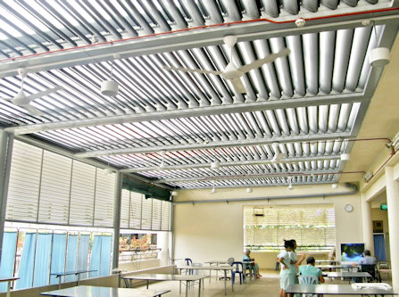
The trellis roof can also be installed for indoor/outdoor balcony to create a spacious cool and relax area.
Feel the outdoor air breeze without too much hot and sunny sun shine. Nice natural lighting and cool open space.
This aluminum roofing system is designed to be light weight yet robust against strong wind and rain fall. Suitable for indoor and outdoor installation.
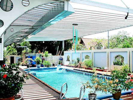
Trellis roof system provides shades for your outdoor pool during a sunny day as well as raining days.
When the weather is good, the trellis can be open up to allow for shine and breeze through the open area.
Enjoy your pool with comfort.
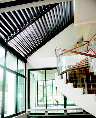
This is an indoor trellis roof canopy structure installation for a corridor inside the house.
Allows outside natural light and air breeze to enter into the house.
Makes the house cooler, brighter while using less energy.
The rain sensing mode will automatically close up the trellis to ensure that your indoor environment is keep dry and clean.
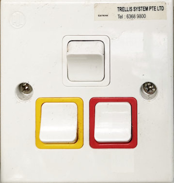
Operating Instruction
The trellis roof control is simple to operate. One button to open and another button to close the trellis.
The trellis system also comes with a rain sensor. When rain is detected, the trellis shelter can automatic close up itself so that your corridor stays dry.
An optional external buzzer can be install for auditory feedback to the user.
Opening Closing Trellis
A single push and release on the open button, the trellis will open to its preset half opening position. This preset position can be adjusted form the blue color POT on the circuit board. Another push and release will fully open the trellis.
A single push and release to the close button will fully close the trellis.
For controlling of the trellis opening to your preference, you can simply push and hold the button, to open/close the panel, and release the button when the panel reaches the position that you want.
Rain Detection
Rain detection mode can be activated to automatic control the trellis when it rains. The trellis will automatically be closed and do not allow to be open until the water gets dry out.
To open the trellis manually while the trellis is still wet, you have to switch off the rain detection mode first.
User can select this rain detection mode via a switch. The rain sensor mode indicator will get light when this mode is selected. When it is in OFF mode, the indicator will be turned off. This indicator will blink when rain is detected. If the rain mode is switched ON, the lighted indicator will starts to blink when rain is detected. Even if the rain mode is switched OFF, the indicator light will still blink when rain is detected, just that the blinking rate is slower.
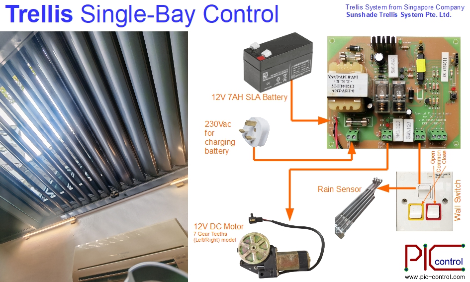
System Connection Wiring
This section shows how
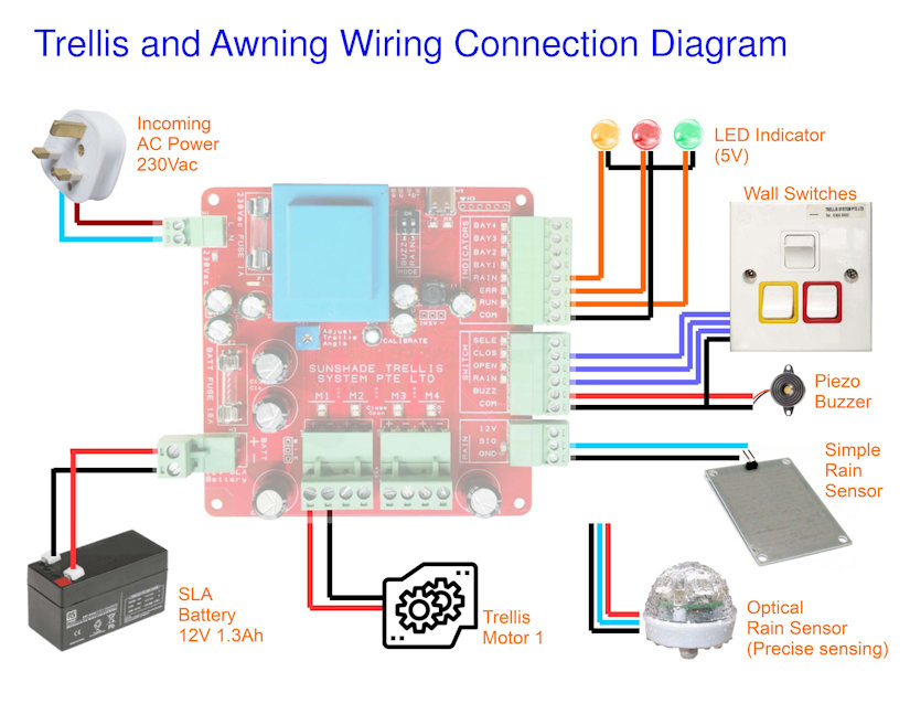
(for single bay Trellis installation)
Low cost rain sensor can be connected to this board to detect raining event. If the rain sensing mode is active, the trellis will automatically close itself to shelter away from the water. If you like the trellis to reacts faster to the rain, you can choose to install optical rain sensor instead. It is more precise in the rain sensing and can react faster to raining and rain stopping. You can order optical rain sensor from PIC-CONTROL.
Trellis Roof Controller Board
This is the main controller board for the trellis automated roofing system. It is the main board for driving the geared DC motor of the trellis system. Design to drive geared DC motor with a rating at about 1A (when it moves), and a stall current at about 8A to 10A.
The following is the description of the controller board.
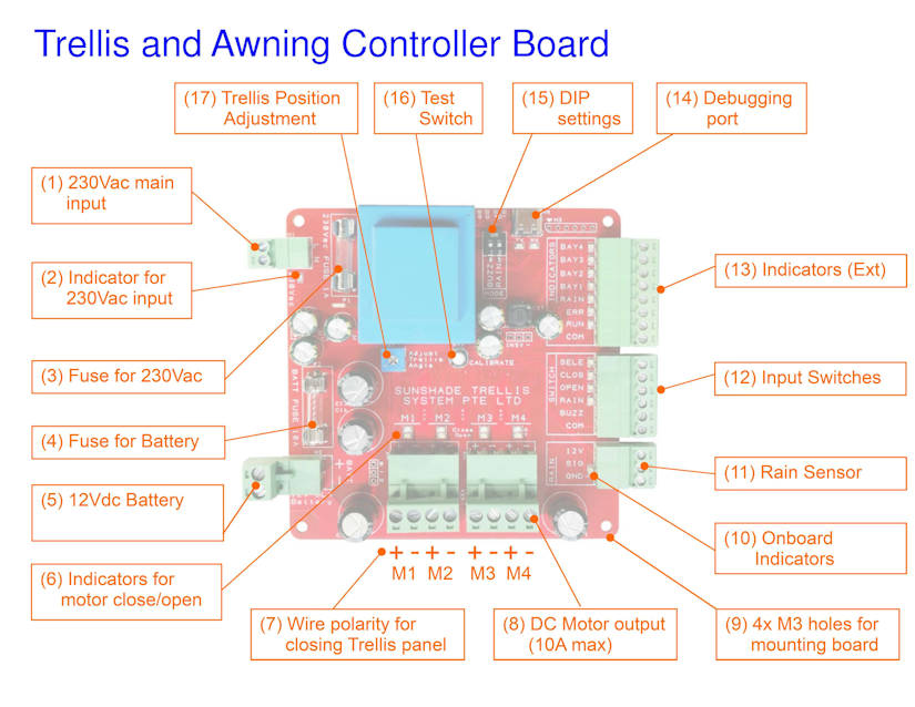
(01) 230Vac mains incoming power input
230Vac is required for charging of the SLA battery.
(02) Indicator for 230Vac incoming power
Green indicator will gets lighted up when there is power coming from the 230Vac input.
(03) Fuse for 230Vac
Fuse of 1A is recommended for protection from the 230Vac incoming mains power source.
(04) Fuse for Battery
Fuse of 10A to 15A is recommended for protection from the battery.
(05) SLA Battery
Sealed Lead Acid Battery. Recommending 12V 1.3Ah capacity battery (97 x 43 x 51mm). Larger size 12V 7Ah SLA battery (152 x 66 x 94mm) can also be use.
This battery is used for driving the DC motor of the Trellis.
(06) Indicators for Trellis motor
When the controller is driving the Trellis motor to close, Green indicator will gets lighted up. For opening of the Trellis, Yellow indicator will gets lighted up.
(07) Motor Wire polarity (closing the Trellis)
Motor wire polarity for closing the Trellis panel is motor positive terminal on the left (pin 1), and negative terminal on the right (pin 2). Apply this polarity should activate the motor to close the Trellis.
(08) DC Motor output
DC motor output is design for driving a DC motor up to a maximum current of 10A. Typical operating current is about 1A, and can spike up to 8A to 10A when the motor is in a stalled position.
(09) Mounting Holes M3 x 4
Mounting holes available at the 4 corner of the board. Design for M3 screw mounting. Distances between the mounting holes are about 91.5mm apart.
(10) Onboard indicators
Indicators onboard for technician monitoring and troubleshooting use.
(11) Rain Sensor interface
This interface allows a simple resistivity rain sensor to be connected via two wire, signal and ground pins.
It can also connect to a more sensitive and responsive optical rain sensor for a better user experience.
(12) User switches and buzzer interface
Switch buttons for user to control and beep sounder feedback.
- Open Trellis
- Close Trellis
- Rain Sensing Mode
- Bay Select
- Beep Sounder
(13) External Indicators
User indicators for operation and monitoring.
- RUN
- ERROR
- RAINING
- BAY 1 (available in 4 bay controller board)
- BAY 2 (available in 4 bay controller board)
- BAY 3 (available in 4 bay controller board)
- BAY 4 (available in 4 bay controller board)
(14) Debugging port
USB debugging port for monitoring purpose. It is a virtual serial communication port with the following settings,
- baud-rate 115200bps
- No Parity
- 8 Data bits
- 1 Stop bits
(15) DIP switches
— Not available —
(16) Test switch
— Not available —
(17) Trellis position adjustment POT
When the open button is pressed for the first time from the Trellis panel closed position, the panel will open to the half open panel position. This half open panel position can be adjusted to your preference by adjusting this (17) Trellis position adjustment POT.
Battery Power and Protection System
The whole system is powered by a 12Vdc SLA Battery (Sealed Lead Acid Battery). A battery capacity of 1.3Ah is enough for typical operation.
The charging of this SLA battery is supplied via the 230Vac power input. This power do not supply power to the trellis. It is only used for charging the connected SLA battery. If the SLA battery is not connected, the system will not be able to operate correctly. This 230Vac do not have enough power to drive the trellis motor. A 1.3Ah SLA battery capacity can drive the Trellis for about 30min to 60min without any charging. It is ok to install a high capacity battery if want the system to operate longer when AC power is not available (A power blackout scenario).
A battery monitoring is designed onto the system. If the voltage level of the battery falls below a healthy level, the ERROR indicator will start blinking. When this happens, the controller will only allow user to close but not open the trellis. This is to protect the battery from over draining itself, and to conserve the energy so that it can have enough power to close up the trellis when it detect rain. If the blinking appears, you can simply wait for a while. The battery will be charged up, and allow for normal operation again. This can happen when someone is operating the trellis for a continuous period of 30min or more, or if the battery becomes faulty after long use.
It is recommended to replace the battery every 4-5 years of operation.
The system ERROR indicator will appeared to blink faster if the battery is suspected to be faulty. If this happens, leave the system alone for 24 hours. If the ERROR indicator blinking persist, please contact for technical support. It could likely be cause by the following…
- No incoming 230Vac power supply.
- Faulty charging circuit.
- Battery is faulty (normal wear & tear).
The technician will diagnose and help you rectify the problem.
Technical Specification
- Board power consumption is about 1W, up to 12W max
- AC Power Input: 230Vac 0.1A (for battery charging purpose)
- DC Power Input: Sealed Lead Acid Battery SLA 12Vdc 1.3Ahr (for motor operation)
- Output driver support geared DC motor of 12Vdc 1A (10A max rating)
- Support low cost resistive, or high precision optical rain sensor.
Cable current capacity for the Battery and Motor can operate peak at about 10A. Cable gauge size of AWG16 is recommended.
Trellis Controller Board Dimension
The physical board size is about 99 x 99 x 36mm.
Propose M3 mounting hole position is 91.5 x 91.5mm.
(mounting hole size is 3.2mm, suitable for M3 size screws)
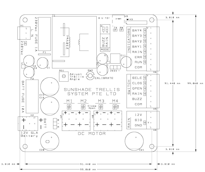
The weight of this board is about 350g.
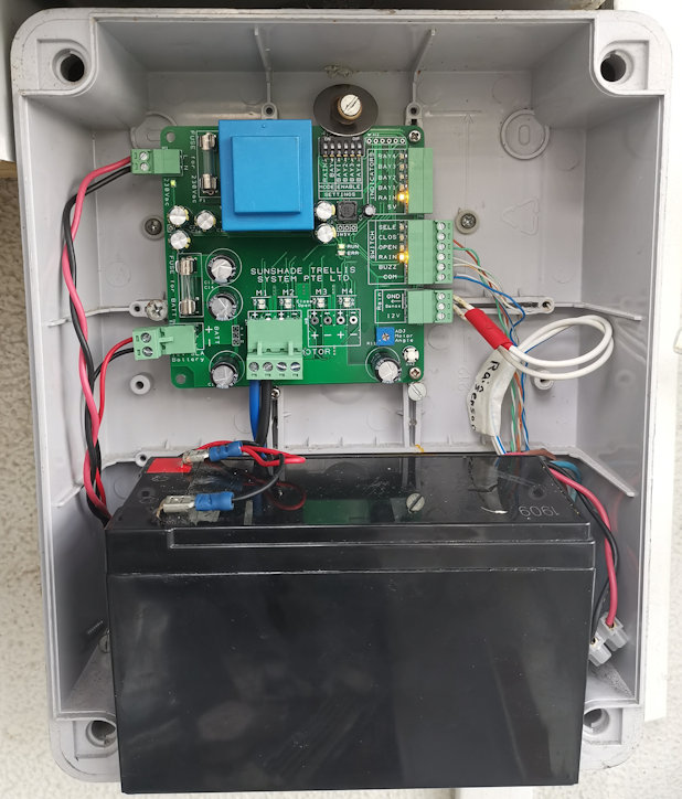
Deployed Site Installation
This is a installation for a single bay Trellis controller.
The board requires a 12Vdc Seal Lead Acid battery to function and for powering up the motor. Battery as small as 12Vdc 1.2Ahr battery can be use. (can continuously operates for about 45 minutes without the charging 230Vac power mains)
Troubleshooting
| Symptom Observation | Possible Cause |
| Error Buzz Tone | This is the most common feedback from a user. A low sound tone sounded when the switch is pressed. This can occurred when the Trellis is not allowed to be opened when it is raining and the rain sensing function is enabled. Error buzz tone will also sound when you are trying to open the Trellis when the battery charge is low or the battery is faulty. |
| ERROR Indicator Blinking (slow). | Battery voltage is low. Low in charge. This may also happen if 230Vac is not connected, or the charging circuit is faulty. If the system has been operating open/close action for long period of time, this may happen too. To conserve energy during this period, the Trellis can be close but cannot be open. You can wait for 24 hrs for the battery to be charged up before you can operate it normal again. |
| ERROR Indicator Blinking (fast). | Battery voltage is super low. Battery probably needs a replacement. Please call for technical support. |
| Cannot open Trellis. | Check if ERROR indicator is not blinking. If it is blinking, read up the possible cause above. You can If the Rain indicator is blinking. The Trellis will not allow to be open, if battery level is low. You can wait for 24 hrs for the battery to be charged up, and attempt to open again. The trellis will also not open if the rain sensing is enabled and water is detected. You can disable the rain sensing function, and open the Trellis. If no indicator is blinking and the Trellis cannot be open, please call for technical support. |
| Cannot close Trellis. | Please call for technical support. |
| Trellis do not automatically close when it rains. | Please ensure that the rain sensing mode is enable. If rain sensing mode is enabled and the Trellis do not close automatically when it rains, please call for technical support. |
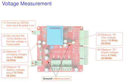
Board Voltage Measurement Test
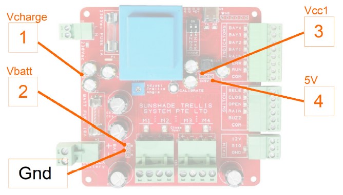
When doing this measurement to test if the board has all the voltage at the correct level, the battery has to be disconnected, and the AC main power input has to be switched on.
With reference to the Gnd pin, the voltage measured from the board labelled no. 1 to 4 should be as follows,
- Vcharge = 14.4V ±0.2V (battery charging voltage)
- Vbatt = 13.7V ±0.2V (battery voltage)
- Vcc = 13V ±0.2V (unregulated supply to the circuit)
- 5V = 5V ±0.06V (regulated supply to the circuit)
Fast measurement tips:
The voltage different between point 1 and 2, point 2 and 3 is about 0.7V differences.
Old Trellis Control Board
For older Trellis control board documentation and references, check out this page here.
Contact Us for further details.
This system is designed and sold by Sunshade Trellis System Pte. Ltd.
Contact them at +65 6368 9800 (office phone), sunshadetrellis@outlook.com (email)
Click here to visit their website at https://sunshadetrellis.wixsite.com/home
Also check out other automated awning retractable roof shade system.