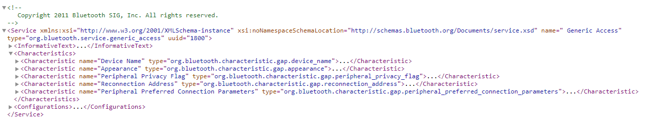
GATT is a protocol style of exchange data over the wireless Bluetooth connection that is introduced for BLE 4.0.
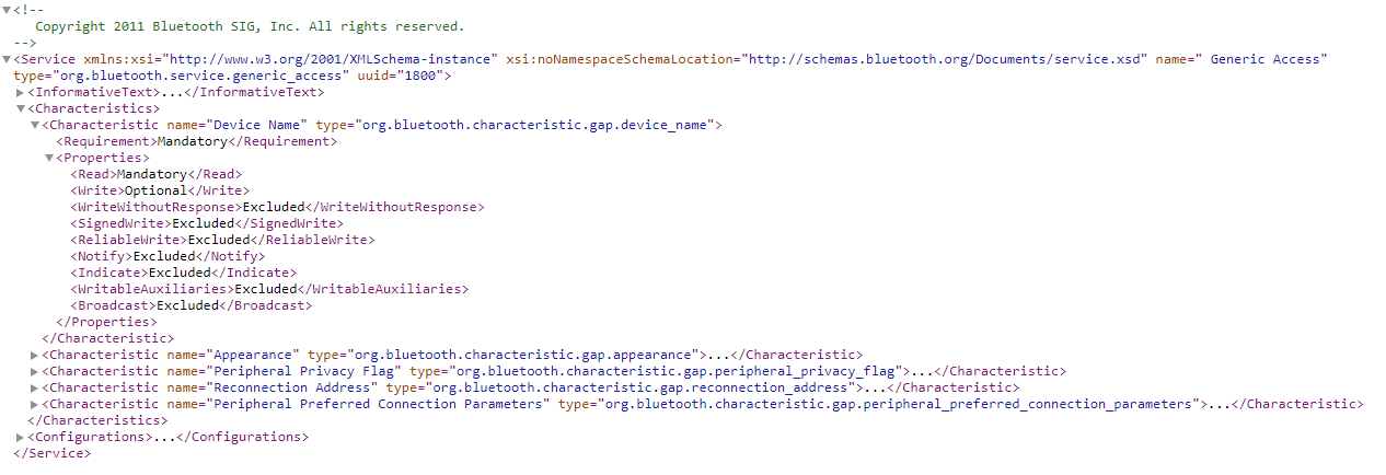
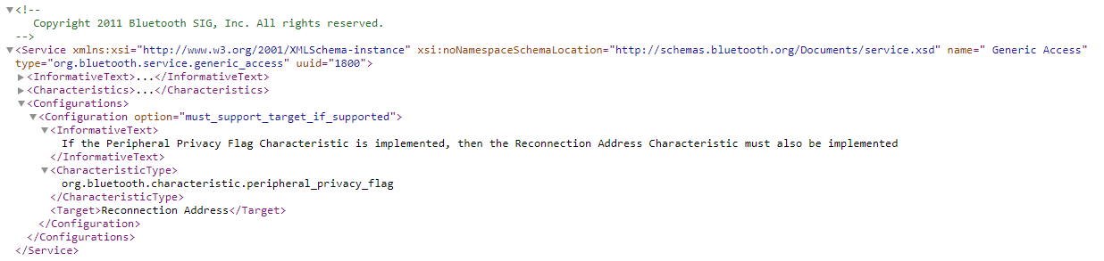
The Bluetooth connection can consist of many services. A service is like data channel or view as a data object passing to and from the Bluetooth device. Inside each service can consist of many data attributes which is also known as the characteristic. Characteristic is simply the data that is associated with a standard defined label.
Topic: – Handler (16 bit ID as and address for the attribute) <- is it address for the Service? – Permission – UUID identify the data attribute type in the data block.
Hands-on GATT protocol
One useful tool in learning the new GATT Protocol designed for Bluetooth Low Energy (BLE4.0 and above) is using the nRF Connect’s Bluetooth Low Energy apps from Nordic. You can install the nRF Connect software to have access to this app.
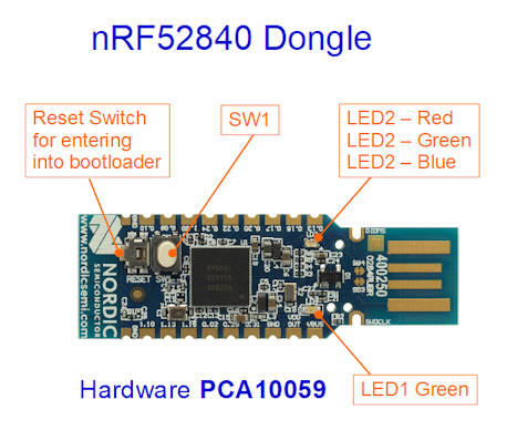
The following example uses nRF52840 Dongle as a sniffer.
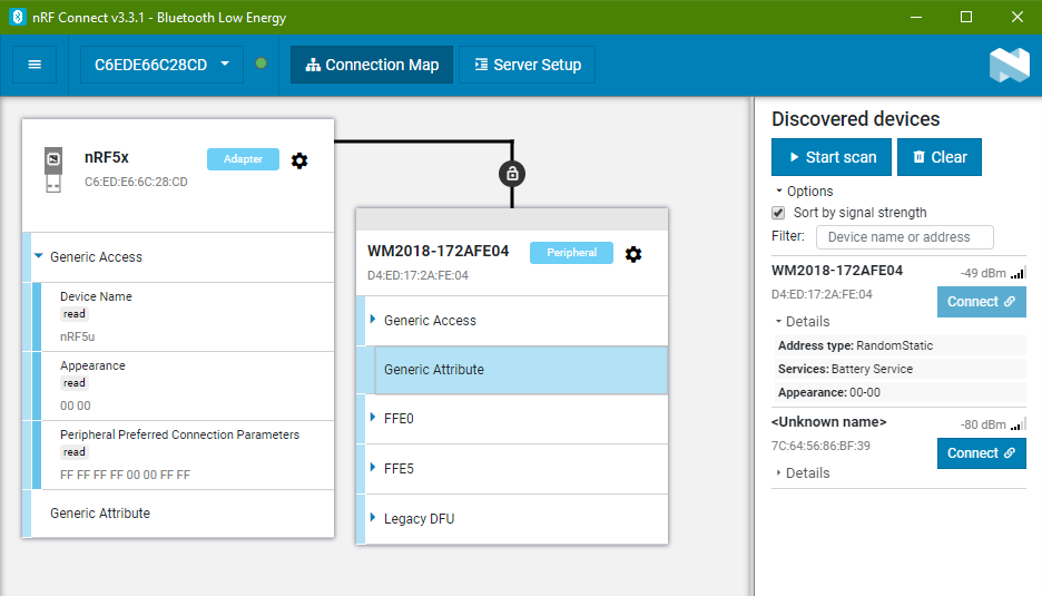
When in the BLE apps, select the dongle device to start.
On the right side, click on the button <Start scan> to scan for nearby Bluetooth devices.
Bluetooth devices is constantly sending our advertisement broadcast so that other Bluetooth client can detect it and be able to connect to it.
In the following example, a BLE device is detected by the scan process. The device name ending with “…..-172AFE04”. Select the device and click on the <Connect> button.
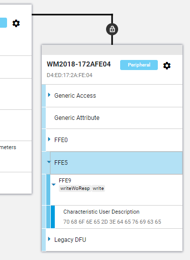
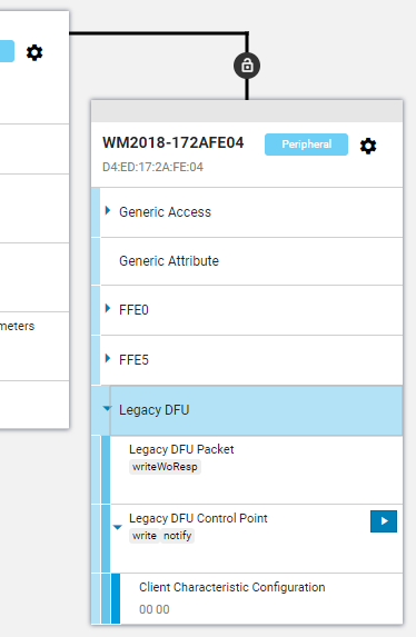
The column on the left represents the nRF52840-Dongle which is now a Central Bluetooth device. The right column is displaying the connected Bluetooth Peripheral (server) device name “…..-172AFE04”. The central is a Bluetooth client device which can connect to one or more peripheral devices. Each peripheral (server) can only accept one connection from the central (client) Bluetooth device. Once the peripheral is connected, they will stop their advertisement broadcast. Other Bluetooth devices will not be able to see and connect to them.
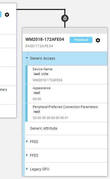
In the connected peripheral Bluetooth device with name ending with “…..-172AFE04”, along the connection line, there is a lock icon. Hover your mouse to check up the connection information. The configuration icon inside the device box have option that allows you to disconnect the Bluetooth connection of the central device to the peripheral device.
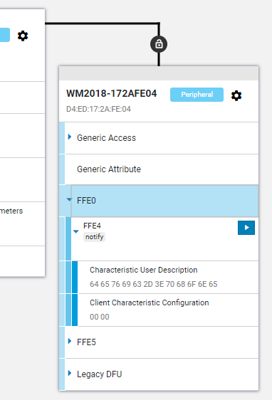
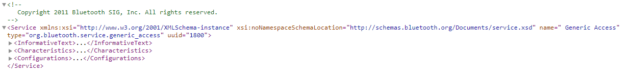
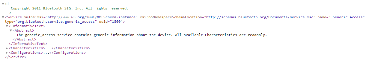
Inside the peripheral device, you will notice the following section of data. These are the GATT Services available from this server peripheral Bluetooth device.
Note that ↵ means sending of char 0x0D 0x0A (<CR><LF>)
//Test if modem is connected
? AT ↵
? OK ↵

//Get the modem firmware version
? AT+CGMR ↵
? 352656100032351 ↵

//Get IMEI number
? AT+CGSN ↵
? 352656100032351 ↵

//Sim Activation
? AT+CFUN=0 ↵     //turn  off cellular functionality
? OK ↵
? AT+CFUN=1 ↵     //turn  on cellular functionality
? OK ↵

//PDP Context Configuration (configure how the data packet be accepted by the telecom)
Maybe useful AT commands
AT+CGPADDR //show IP address allocated by the network
AT Command for iBasis SIM card using nRF9160 (with help from iBasis technical team)
AT+CFUN=0                           //Power of the modem every time that you change the access mode LTE-M or NB-IoT

AT%XSYSTEMMODE=1,0,1,0              //Enable LTE-M1

AT%XSYSTEMMODE=0,1,0,0              //Enable NB-IOT

AT+CGDCONT=0,"IP","ibasis.iot"      //Configure APN (Optional)

AT%XBANDLOCK=1,"10001000000000000"  //Lock the specific band for your testing, put 1 at the position of specific band (17 and 13 on this example, this is Optional)

AT+CPSMS=0                          //Disable PSM

AT+CFUN=1                           //Enable modem

AT%XSIM?                            //Enable UICC

AT+CFUN?                            //Register

AT+COPS?                            //Search network available
AT Command useful reference with other modems
AT+CSTT               //specify APN
AT-CIPPING            //ping to server to check connectivity
NB-IoT locks are digital locks that can be authenticate and unlock itself wirelessly.
NB-IoT is a communication method similar to the data network that we are using for our mobile phone. So this means that the lock can be remotely control over the cellular data network.
NB-IoT has a lower cellular cost compare to LTE-M, LTE network.
Useful coding references for nRF52840 microcontrollers
Variable Declaration
Variable
signed char,   int8_t
unsigned char, uint8_t
signed short,  int16_t
unsigned short,uint16_t
signed int,    int32_t
unsigned int,  uint32_t
signed long,    int64_t
unsigned long,  uint64_t
Useful Basic Function
nrf_delay_ms(500);                 //delay in msec
bsp_board_init(BSP_INIT_LEDS);     //initialising LED
bsp_board_led_invert(0);           //toggle LED
nrf_gpio_pin_set(LED_1); or bsp_board_led_on(0);
nrf_gpio_pin_clear(LED_1); or bsp_board_led_off(0);
LED_1 = NRF_GPIO_PIN_MAP(0,13)
All the function is written in a manner that is portable and general purpose coding. This may make it very difficult to read and understand. But basically, it works like PIC microcontroller where each pin or peripheral can be individually configure.
The entry point to the program is at “main.h” -> “int main(void)”.
Hardware specific “fixed” configuration are all done in “pca10056.h“. All pins input/output definition are configured in this file which is very specific to this designed pca10056 circuit board.
“boards.c” contains generic codes for managing the LED and Push Buttons codes.
Project (Solution) specific codes will be under the Application folder. Usually consist of “main.c” where the code starts, and “sdk_config.h” where are the configuration of the application will be.
Function that starts with sd_XXXXXX(), these are the basic functions provided directly from softdevice API module.
Function that starts with nrf_XXXXXX(), these are functions by nRF encapsulation softdevice API sd_XXXXXX().
Data type naming convention ends with XXXXXX_t
sec  - security
conn - connection
lbs  - led button service
ble  - Bluetooth low energy
params-parameters
auth - authorised
evt  - event
adv  - advertisement
lesc - LE security
len  - length
gattc_evt- GATT client event
gatts_evt- GATT server event
Pin maps for the nRF52840-DK board examples demonstration
Peripherals
Pin out in the nRF52840 example demo
LED1
P0.13
LED2
P0.14
LED3
P0.15
LED4
P0.16
SW1
P0.11
SW2
P0.12
SW3
P0.24
SW4
P0.25
UART-RX
P0.08
UART-TX
P0.06
One of the more important BLE event function
This ble_evt_handler() is callback whenever the BLE events occurs. The lower level will be called and propagated up to our application level through ble_evt_handler() where we will handle the BLE message.
For interrupt there are a total of 4 levels. Highest interrupt priority is taken by SoftDevice, the next level is by the application. Followed by a lower priority SoftDevice, then the lowest priority to the application.
/**@brief Function for handling BLE events.
 *
 * @param[in]   p_ble_evt   Bluetooth stack event.
 * @param[in]   p_context   Unused.
 */
static void ble_evt_handler(ble_evt_t const * p_ble_evt, void * p_context)
The path of the incoming data event (BLE_GATTS_EVT_WRITE) start from ble_conn_params.c->ble_evt_handler(ble_evt_t const * p_ble_evt, void * p_context), then followed by ble-lbs.c->ble_lbs_on_ble_evt(ble_evt_t const * p_ble_evt, void * p_context) then main.c->ble_evt_handler(ble_evt_t const * p_ble_evt, void * p_context)
For the event object p_ble_evt, the data structure is very large. But not all data in the structure are valid. It depends on the event that had took place. Read only that section of the structure. nRF simply lump everything into this single data structure. In actual fact the data communication isn’t so large.
nRF Object Class Documentation
Application Level
---------------------------
ble_lbs_c.c
- LED Button Service modules

Middle Level
---------------------------
nrf_ble_gq.c
- GATT request queue module. Commands from application to SoftDevice are put to a queue system here

Close to SoftDevice Level
---------------------------
nrf_sdh.h

Low Level (Hardware)
---------------------------
boards.h, pca10056.h, bsp.h
- hardware board related. Board Support Package
nRF Singleton Object Instance
m_ represent singleton object.

m_ble_lbs_c
- LED Button Service object for the Central device

m_scan
- BLE scanning object

m_gatt
- GATT object

m_db_disc
- DB Discovery object

m_ble_gatt_queue
- GATT queue object
p_ represent pointer to object
//Explore Variable p_ble_evt
    //  p_ble_evt
    //      header
    //          evt_id          //type of Bluetooth events
    //          evt_len
    //      evt
    //          common_evt      //common event
    //              conn_handle
    //              params
    //                  user_mem_release
    //                  user_mem_request
    //          gap_evt         //GAP originated event
    //              conn_handle
    //              params
    //                  adv_report
    //                  adv_set_terminated
    //                  auth_key_request
    //                  auth_status                     //(ble_gap_evt_auth_status_t)
    //                      auth_status                 //< Authentication status, see @ref BLE_GAP_SEC_STATUS.
    //                      error_src                   //< Authentication status, see @ref BLE_GAP_SEC_STATUS.
    //                      bonded                      //< Procedure resulted in a bond.
    //                      lesc                        //*< Procedure resulted in a LE Secure Connection.
    //                      sm1_levels                  //< Levels supported in Security Mode 1.
    //                          lv1
    //                          lv2
    //                          lv3
    //                          lv4
    //                      sm2_levels                  //< Levels supported in Security Mode 2.
    //                          lv1
    //                          lv2
    //                          lv3
    //                          lv4
    //                      kdist_own                   //< Bitmap stating which keys were exchanged (distributed) by the local device. If bonding with LE Secure Connections, the enc bit will be always set.
    //                          enc
    //                          id
    //                          link
    //                          sign
    //                      kdist_peer                  //< Bitmap stating which keys were exchanged (distributed) by the remote device. If bonding with LE Secure Connections, the enc bit will never be set.
    //                          enc
    //                          id
    //                          link
    //                          sign
    //                  conn_param_update
    //                  conn_param_update_request
    //                  conn_sec_update
    //                  connected
    //                  data_length_update
    //                  data_length_update_request
    //                  disconnected
    //                  key_presed
    //                  lesc_dhkey_request
    //                  passkey_diplay
    //                  phy_update
    //                  phy_update_request
    //                  qos_channel_survey_report
    //                  rssi_changed
    //                  scan_req_report
    //                  sec_info_request
    //                  sec_params_request
    //                  sec_request
    //                  timeout
    //          gattc_evt       //GATT client
    //              conn_handle
    //              error_handle
    //              gatt_status
    //              params
    //                  attr_info_disc_rsp
    //                  char_disc_rsp
    //                  char_val_by_uuid_read_rsp
    //                  char_vals_read_rsp
    //                  desc_disc_rsp
    //                  exchange_mtu_rsp
    //                  hvx
    //                  prim_srvc_disc_rsp
    //                  read_rsp
    //                  rel_disc_rap
    //                  timeout
    //                  write_cmd_tx_complete
    //                  write_rsp
    //          gatts_evt       //GATT server
    //              conn_handle
    //              params
    //                  authorize_request
    //                  exchange_mtu_request
    //                  hvc
    //                  hvn_tx_complete
    //                  sys_attr_missing
    //                  timeout
    //                  write
    //          l2cap_evt       //L2CAP, Logical Link Control and Adaptation Layer Protocol
    //              conn_handle
    //              local_cid
    //              params
    //                  ch_sdu_buf_released
    //                  ch_setup
    //                  ch_setup_refused
    //                  ch_setup_request
    //                  credit
    //                  rx
    //                  tx
Naming convention used in nRF SDK BLE codes
....xxx_t => the "_t" defines the data object type.

scan_evt => scan event data to the main application

nrf_ble_scan => Bluetooth scanning parameters

ble_gap_evt_adv_report => Advertise Report object
ble_evt_t -> ble_gap_evt_t -> ble_gap_evt_adv_report_t

ble_gap_evt => GAP event

//Advertise Data
p_adv_report->data.p_data => Advertising data pointer
p_adv_report->data.len => Advertising data length
Example data:
03 19 00 00 02 01 06 0E |........
09 4E 6F 72 64 69 63 5F | Nordic_
42 6C 69 6E 6B 79       |Blinky

Advertise data starts (length of 22 of the whole packet)
This advertise packet consist of 3x Advertising Data (AD) elements

First byte 03 indicates the length of the first element which is 03 19 00 00.
19 is the AD type «Appearance»
00 00 is the data for Appearance which is unknown
The next set of AD element is 02 01 06.
First byte 02 indicates the length.
01 is the AD type for «Flags»
06 is the data for flags.
It indicates that BR/EDR is Not supported, and LE General Discoverable Mode is true.
The next set of AD element is 0E 09 4E 6F 72 64 69 63 5F 42 6C 69 6E 6B 79
0E is the total number of data bytes which is 14.
The AD type is 09, which stands for «Complete Local Name».
The data 4E 6F 72 64 69 63 5F 42 6C 69 6E 6B 79 represent "Nordic_Blinky" which is the name of the device.

The AD type code can be found on this page,
https://www.bluetooth.com/specifications/assigned-numbers/generic-access-profile/
Notes: Possible point of improving Bluetooth product.
Company Identity. Register for an unique company ID code, and implement into Bluetooth product. Display of Nordic ID 0x0059 as the company ID can be a security breach. https://www.bluetooth.com/specifications/assigned-numbers/company-identifiers/ https://www.bluetooth.com/develop-with-bluetooth/join/ https://www.bluetooth.com/develop-with-bluetooth/join/membership-benefits/ https://devzone.nordicsemi.com/f/nordic-q-a/7594/about-company-identifiers https://devzone.nordicsemi.com/f/nordic-q-a/2636/using-nordic-manufacturer-id-in-advertizing-data https://devzone.nordicsemi.com/f/nordic-q-a/24449/advertising-manufacturing-specific-data-without-company-id
Bluetooth protocol operates at 2.4GHz, same as ZigBee and WiFi, working in the same unlicensed ISM frequency band.
Each network (Piconets) consist of a coordinating Master and many connecting Slaves.
Bluetooth Profile
Bluetooth profile is like the many various protocol of bluetooth communication. Some profile are for keyboards, some for storage, some for audio. Here are a list of commonly used profiles.
Serial Port Profile (SPP), or sometimes known as UART
Human Interface Device (HID)
Hands-Free Profile (HFP)
Headset Profile (HSP)
Advanced Audio Distribution Profile (A2DP)
A/V Remote Control Profile (AVRCP)
Generic Attribute Profile (GATT), custom profile communication using Attribute Protocol (ATT) between the master and slave.
GATT is typically used for proprietary project that uses custom communication through the use of exchanging attribute data (Attribute Protocol, ATT).
A temperature sensor device can be acting as a server providing a service to expose the temperature reading.
A mobile smart phone is this case is a client, sending commands, requests and accepts incoming notifications/indications from the server.
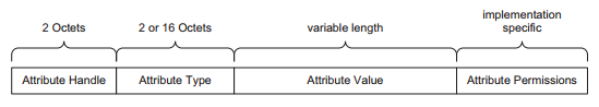
The ATT attributes is made up of 4 components.
Attribute Handle (the address of this attribute during the connection session) 2 bytes address (0x0001-0xFFFF)
Attribute Type (UUID Universally Unique Identifier) 2 or 16 bytes
There are 4 ways of loading your program onto Nordic chip.
Debug header (for use of programming of the full image of the chip memory *.hex). This can be done using nRF52840-DK or nRF9160-DK board as a J-LINK programmer, or using a J-LINK programmer like the j-link Base, j-link BASE Compact or J-Link EDU Mini Programmer.
USB Bootloader (USB Wired DFU, programming of the non-boot loader, application memory *.hex). This can be done using the onboard USB peripheral.
Bluetooth Firmware Loader (Wireless DFU, programming of the non-boot loader, application memory *.bin). This can be done when your chip is pre-flash with bootloader firmware and SoftDevice firmware.
USB Mass Storage (drag and drop *.hex file into the JLINK storage drive to automatically program the chip). This can be done through the nRF52840-DK or nRF9160-DK board.
Tools Required
An nRF52840-DK kit board to act as the programmer for the chip
This is the most fundamental method of loading in firmware into the Nordic nRF52840 chip.
Connect up the nRF52840-DK or nRF9160-DK kit. They are used as a programmer in this example. These boards contains a programmer chip that uses Jlink driver for connection as a programmer, to upload *.hex file into the nRF52840 or nRF9160 chips.
There is typically 3 *.hex module that you need to load into the chip’s memory. Namely,
Bootloader
Soft-Device
Your Application
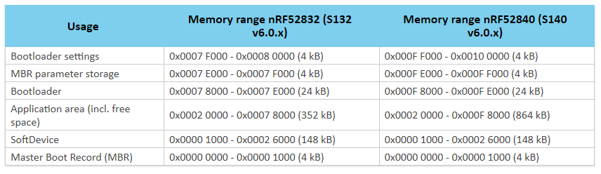
Different chip has its own memory map where the *.hex file should be loaded to. Here is the memory map for nRF52832, nRF52840.
Memory Map of nRF52832 and nRF52840
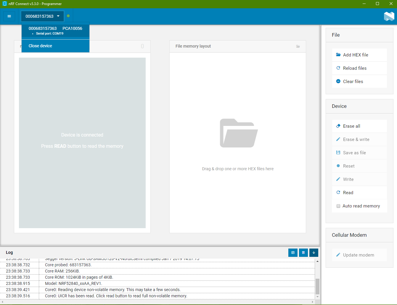
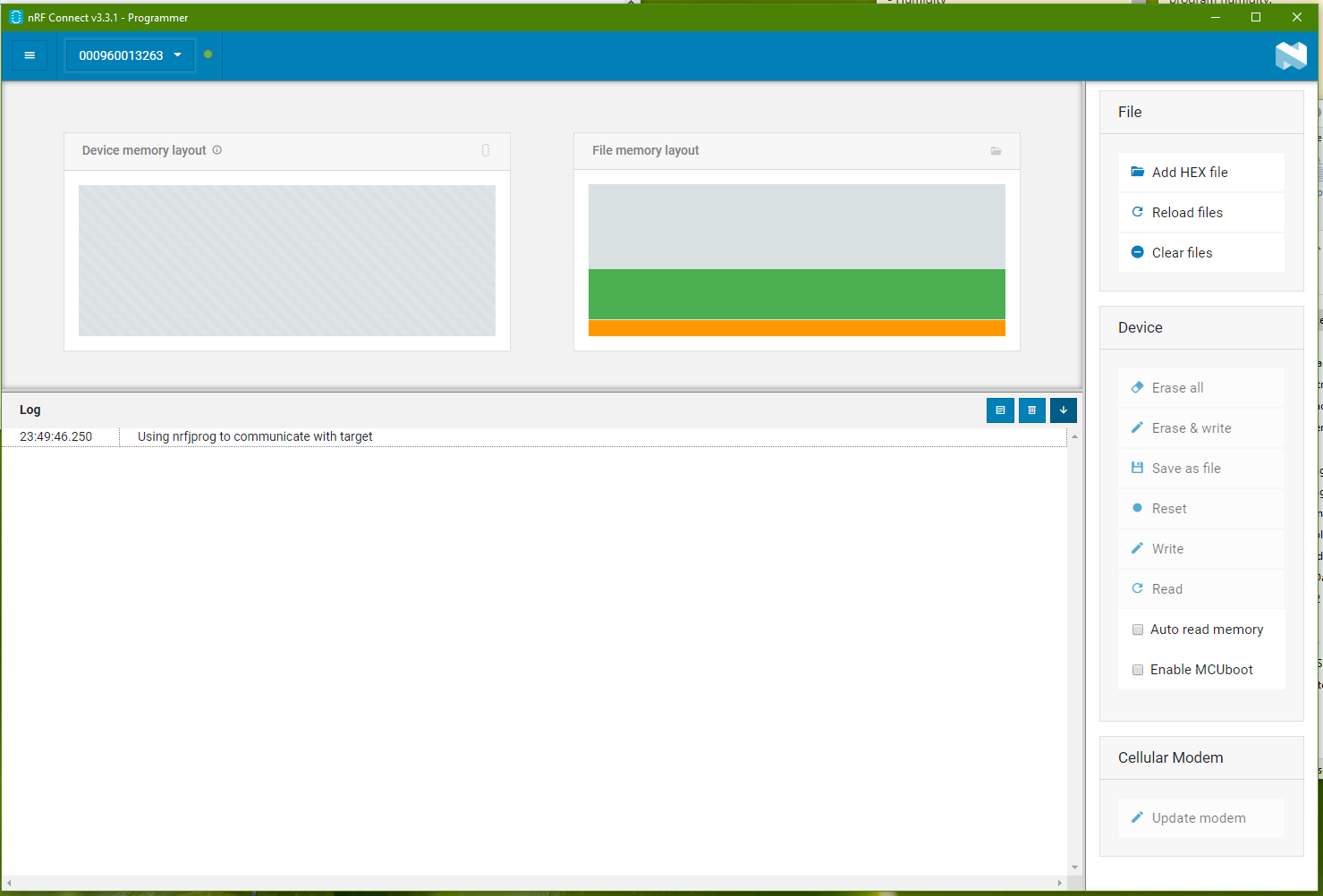
Go to the software “nRF Connect” and open the “Programmer” program.
You will come to the screenshot as follows.
Selecting Programmer Board
There is a drop-down list on the top. When you board is connected, there should be an option in the drop down list for you to choose from. Select the programmer shown in the list.
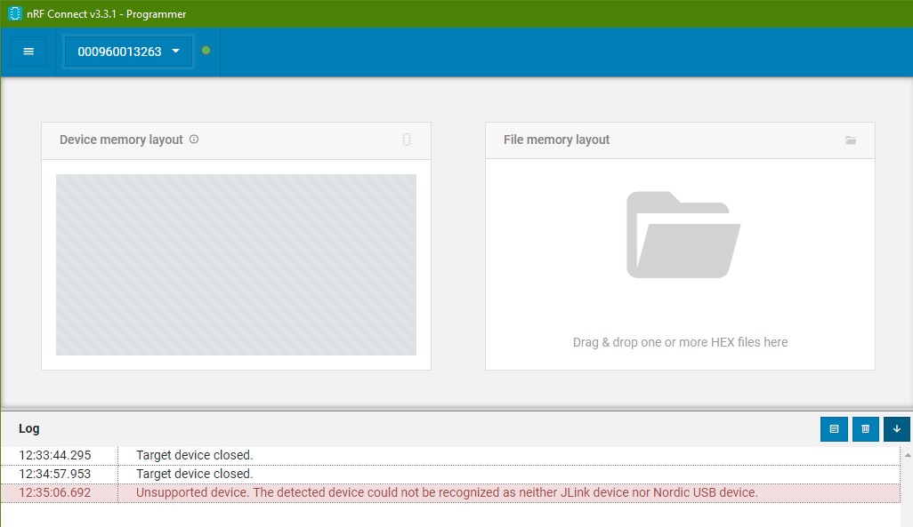
If there is no board listed even when you got your board connected to the computer. You may also see error message in red color at the log box below. Check out the last section to see if there is a solution to resolve your problem.
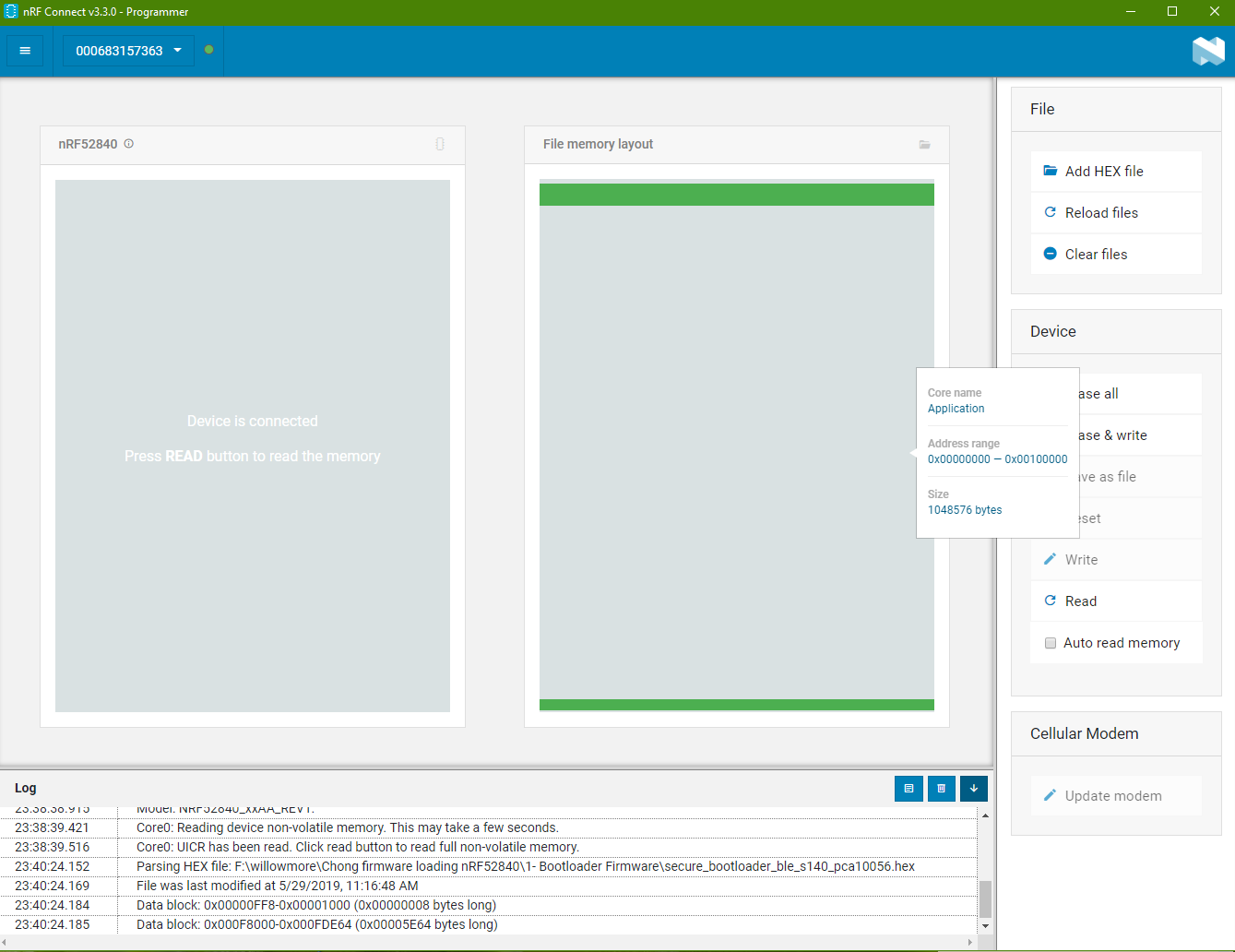
Load Bootloader *.hex file
Bootloader *.hex file is the part that allows you to use USB cable to directly load the program into the chip.
It enables the chip to be able to receive it firmware through wired USB.
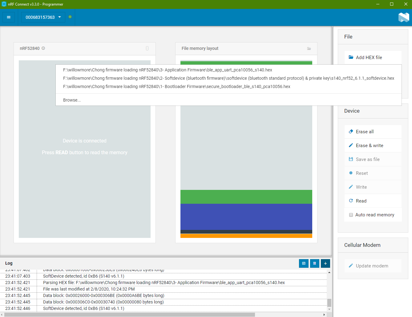
Click on the “Add HEX file” on the right side. Choose the bootloader that you want to use.
On the memory map, you will see green (bootloader sectors in use) on the top and bottom of the memory map.
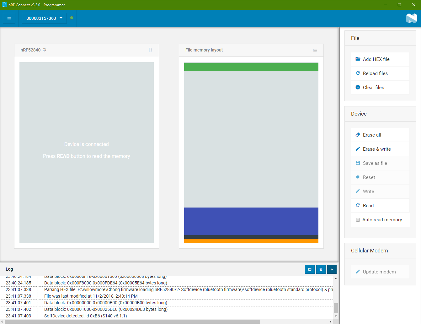
Load SoftDevice *.hex file
SoftDevice is a bluetooth stack codes that you can choose to load into the chip.
Click “Add HEX file” again to load SoftDevice *.hex file.
The SoftDevice *.hex file is loaded in the other memory of the chip. You can see from the purple color zone in the memory map shown on the right side box.
Load Application *.hex file
Lastly, this is the *.hex file for your custom application.
Click on “Add HEX file” again and select the *.hex file of your application.
Download Code into the Chip
Click on the button “Erase & write” to start down loading the firmware containing the 3 sector of the *.hex code into the chip at one go.
nRF52840, “Hello World” Example
Let’s use a simple project “Blinky” as our hello world example to help you kick start your chip programming experience.
Problem Encounter Case Study
Problem encounter from, nRF Connect -> Programmer
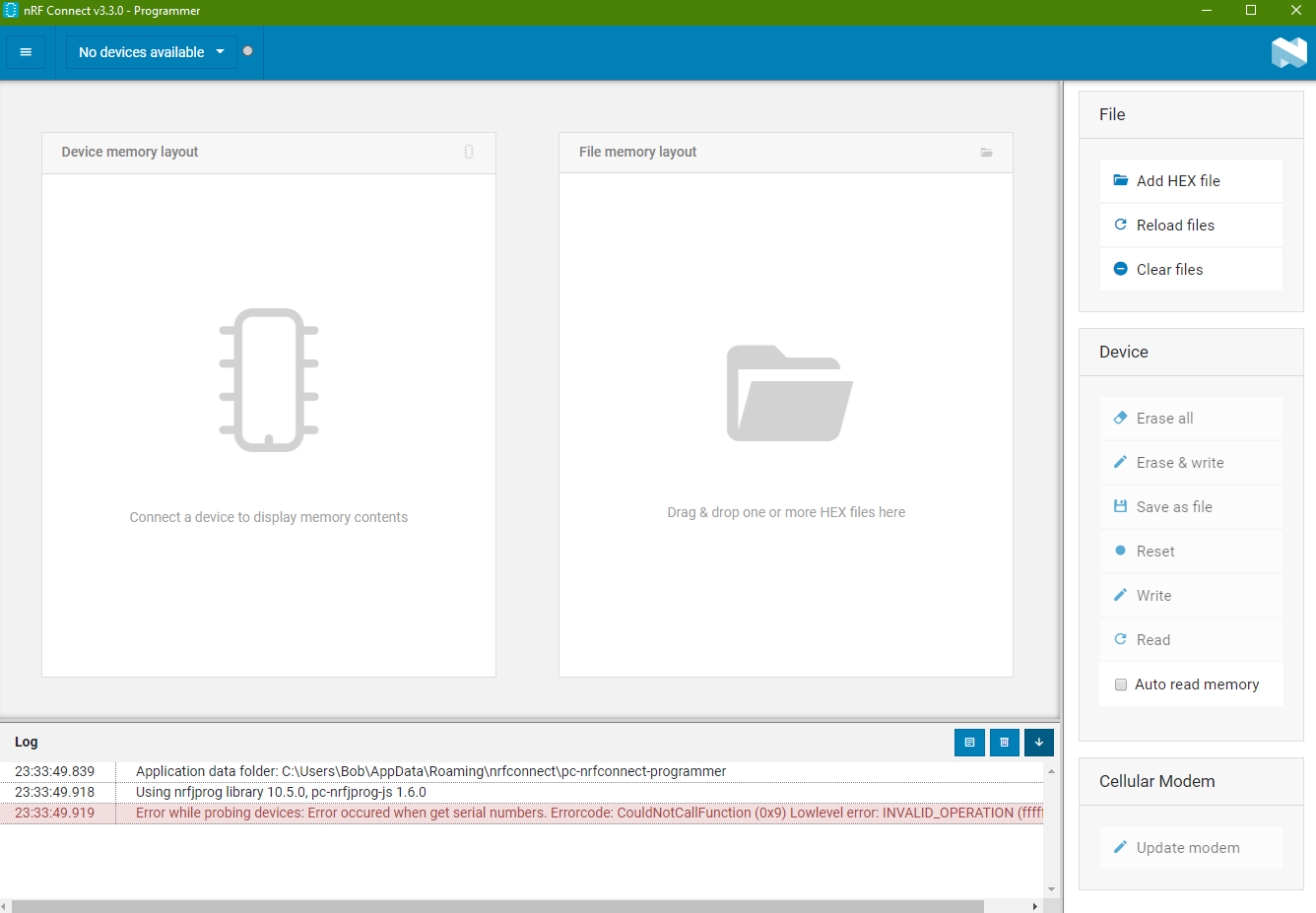
Problem “Error occured when get serial numbers”
Error encounter: “Error while probing devices: Error occured when get serial numbers. Errorcode: CouldNotCallFunction (0x9) Lowlevel error: INVALID_OPERATION (fffffffe)numbers.“
This error occurred if JLINK driver is not installed on the system.
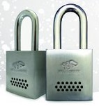
Digital lock pad solution by WillowMore in Singapore.
This product feature a bluetooth smart locks management software system that allows businesses to have stricter lock control system over typical locks with physical keys.
Typical Application
Secure outdoor premises.
Remote telecommunication installation site access.
Benefits
No physical key to manage.
Prevent key duplication, and thief problems.
Smart lock management.
Wireless lock access directly from your mobile phone bluetooth.
Control remote access to vendor or user.
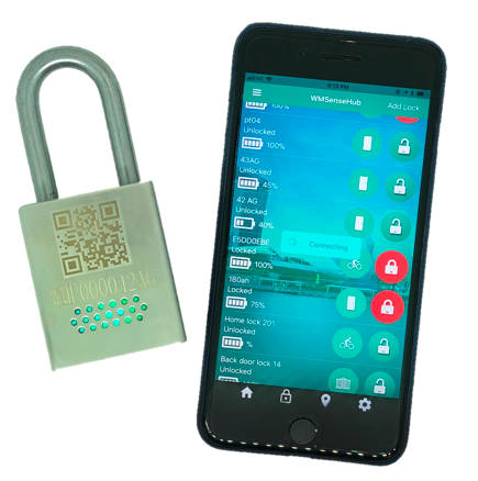
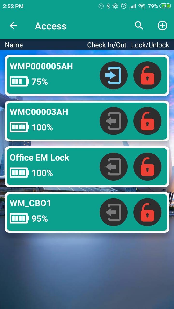
Padlocks Control with Smart Phone Apps
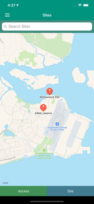
Advance software features to control and manage all your smart locks at different lock with simply your mobile phone apps.
Monitoring individual locks.
Locks’ location map.
Track historical lock access.
Lock management features.
Smart site access.
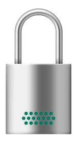
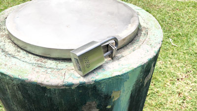
WM Sense Hub
Suitable for Outdoor use
Rain or shine, this padlock is design to withstand hash environment. Press on the lock to wake it up. Use your app to authenticate and request for permission to open the lock.
Instant lock access without managing physical key save time and improves efficiency.
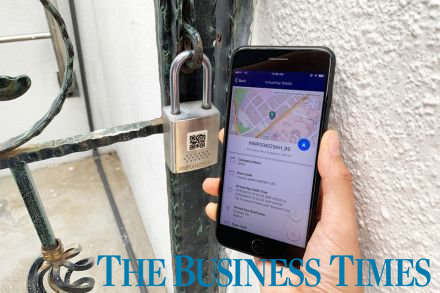
Smart Lock System, News Press Release
Digital padlock system uses bluetooth, design for enterprise asset management to improve the organisation efficiency.