List of
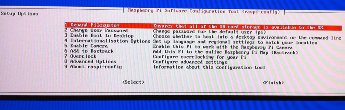
frequently used commands
A list of frequently used Linux command (using Bash Shell) |
Commands
Illustration |
| List directory |
pi@raspberrypi ~ $ ls
Desktop ocr_pi.png python_games
or
pi@raspberrypi ~ $ ls -all |
| Change directory |
pi@raspberrypi ~ $ cd Desktop |
| Returning down one
directory level. |
pi@raspberrypi ~/Desktop $ cd .. |
Access
to /sys directory which is hidden.
Containing system peripherals directory/information, for example GPIO,
I2C, tty (UART, teletype).
http://www.linusakesson.net/programming/tty/index.php |
pi@raspberrypi ~ $ /sys
pi@raspberrypi /sys $ |
| Return to user’s root
directory (~). |
pi@raspberrypi /sys $ cd ~ |
| Rename a file from abc.txt to xyz.txt |
pi@raspberrypi /sys $ mv abc.txt xyz.txt |
| Delete or Remove a file |
pi@raspberrypi /sys $ rm abc.txt |
| Find or search a file name in the sub-directory, where ‘*’ is a wildcard. |
pi@raspberrypi /sys $ sudo find / -name *findText* |
| |
|
| Press up down arrow
keys to scroll through the previously executed commad list. |
|
| Press tab to auto
complete the command, file name, directory name or list all
possibility. Press up down to select related name. |
|
| Shortcut key to open
terminal console <Ctrl+Alt+’T’> |
|
| Create new directory. |
pi@raspberrypi ~ $ mk
DIRECTORY_NAME |
| Remove file. |
pi@raspberrypi ~ $ rm FILENAME |
| Launch GUI, or
Linux’s GUI |
pi@raspberrypi ~ $ startx |
| Stop Linux operating
system |
pi@raspberrypi ~ $ sudo exit
or
pi@raspberrypi ~ $ sudo halt
or
pi@raspberrypi ~ $ sudo shutdown -h
now |
| Reboot Linux
operating system |
pi@raspberrypi ~ $ sudo reboot
or
pi@raspberrypi ~ $ sudo shutdown -r
now |
To get help or further details for any linux command, use the “man” command.
Help manual for any
command or program, where ???? is the
command/program name. |
pi@raspberrypi ~ $ man ????
|
| Pipe following
terminal output text to this grep filter before display on the terminal
console. Only the lines containing the text will be printed out. “XXXX”
will be the command that generate the printed text on the terminal
console, while “TEXT_FILTER” is the text to be
filtered. The operator ‘|‘ pipes the
console output from “XXXX” to the grep
program. |
pi@raspberrypi ~ $ XXXX | grep TEXT_FILTER |
| Direct the terminal
output text, saving to this file.txt |
pi@raspberrypi ~ $ XXXX > file.txt |
| To enable root
privilege. Any command entered will be treated with root privilege as
long as the terminal remains open. |
pi@raspberrypi ~ $ sudo su |
| Allow root privilege
only for the command “XXXX” |
pi@raspberrypi ~ $ sudo XXXX |
Display
the content of the file “XXXX”.
Example to display Raspberry Pi hardware revision, key in “cat /proc/cpuinfo“
Example to display Linux OS information, key in “cat /etc/lsb-release” |
pi@raspberrypi ~ $ cat XXXX
pi@raspberrypi ~ $ cat
/proc/cpuinfoProcessor
: ARMv6-compatible processor rev 7 (v6l)
BogoMIPS : 697.95
Features : swp half thumb fastmult vfp edsp java tls
CPU implementer : 0x41
CPU architecture: 7
CPU variant : 0x0
CPU part : 0xb76
CPU revision : 7
Hardware : BCM2708
Revision : 000e
Serial : 000000005fdceeaf
|
| Execute program in
the background (execute program in a seperated thread), while allowing
the current terminal for other more commands. This is done by appending
the ‘&’ behind a program execution command, which is denoted as
“XXXX”. |
pi@raspberrypi ~ $ XXXX& |
Command “PS” List the program or
threads running in the background of the Linux operating system (for the current user session only).
Where PID is the process ID number.
Command “ps” is a useful troubleshooting tools.
Other related command is “top”.
Other useful troubleshooting commands are,
– “strace“, “ltrace“
– “mtrace“
|
pi@raspberrypi ~ $ ps
PID TTY TIME CMD
2803 pts/1 00:00:02 bash
2948 pts/1 00:00:00 ps
|
To list all the process running in the Raspberry Pi device, use command “PS AX”.
You can see the process created by other user session and you can kill it as well.
These are the bash session started by various user session 0, 1, 2, etc… ,
3477 pts/0 T 0:00 -bash
347? pts/1 T 0:00 -bash
347? pts/2 T 0:00 -bash
This is a bash session started for the main hardware,
2121 tty1 S+ 0:01 -bash
To list only the PID for a particular program, you can use with grep. |
pi@raspberrypi ~ $ ps ax
PID TTY STAT TIME COMMAND
1 ? Ss 0:01 init [2]
2 ? S 0:00 [kthreadd]
3 ? S 0:00 [ksoftirqd/0]
5 ? S< 0:00 [kworker/0:0H]
6 ? S 0:01 [kworker/u:0]
7 ? S< 0:00 [kworker/u:0H]
8 ? S< 0:00 [khelper]
9 ? S 0:00 [kdevtmpfs]
10 ? S< 0:00 [netns]
12 ? S 0:00 [bdi-default]
13 ? S< 0:00 [kblockd]
14 ? S 0:00 [khubd]
15 ? S< 0:00 [rpciod]
16 ? S 0:00 [khungtaskd]
17 ? S 0:00 [kswapd0]
18 ? S 0:00 [fsnotify_mark]
19 ? S< 0:00 [nfsiod]
20 ? S< 0:00 [crypto]
27 ? S< 0:00 [kthrotld]
28 ? S< 0:00 [VCHIQ-0]
29 ? S< 0:00 [VCHIQr-0]
30 ? S< 0:00 [VCHIQs-0]
31 ? S< 0:00 [iscsi_eh]
32 ? S< 0:00 [dwc_otg]
33 ? S< 0:00 [DWC Notificatio]
35 ? S< 0:00 [deferwq]
36 ? S 0:00 [kworker/u:2]
37 ? S 0:08 [mmcqd/0]
38 ? S 0:00 [jbd2/mmcblk0p6-]
39 ? S< 0:00 [ext4-dio-unwrit]
154 ? Ss 0:00 udevd –daemon
1503 ? S 0:01 /usr/sbin/ifplugd -i lo -q -f -u0 -d10 -w -I
1592 ? S 0:07 /usr/sbin/ifplugd -i eth0 -q -f -u0 -d10 -w -I
1778 ? Sl 0:00 /usr/sbin/rsyslogd -c5
1863 ? Ss 0:00 /usr/sbin/cron
1888 ? Ss 0:00 dhclient -v -pf /run/dhclient.eth0.pid -lf /var/lib/dhcp/dhcli
1918 ? Ss 0:00 /usr/bin/dbus-daemon –system
1964 ? Ss 0:02 /usr/sbin/ntpd -p /var/run/ntpd.pid -g -u 102:104
2003 ? Ss 0:00 /usr/sbin/thd –daemon –triggers /etc/triggerhappy/triggers.d
2008 ? Ss 0:00 /usr/sbin/sshd
2037 tty1 Ss 0:00 /bin/login -f tty1
2038 tty2 Ss+ 0:00 /sbin/getty 38400 tty2
2039 tty3 Ss+ 0:00 /sbin/getty 38400 tty3
2040 tty4 Ss+ 0:00 /sbin/getty 38400 tty4
2041 tty5 Ss+ 0:00 /sbin/getty 38400 tty5
2042 tty6 Ss+ 0:00 /sbin/getty 38400 tty6
2044 ? Sl 0:01 /usr/sbin/console-kit-daemon –no-daemon
2111 ? Sl 0:00 /usr/lib/policykit-1/polkitd –no-debug
2121 tty1 S+ 0:01 -bash
2151 ? S 0:00 [kworker/0:0]
2249 ? Ss 0:00 sshd: pi [priv]
2256 ? S 0:00 sshd: pi@notty
2257 ? Ss 0:00 /usr/lib/openssh/sftp-server
2258 ? Ss 0:00 /usr/lib/openssh/sftp-server
2662 ? S 0:00 [flush-179:0]
2663 ? Ss 0:00 sshd: pi [priv]
2667 ? Ss 0:00 sshd: pi [priv]
2674 ? S 0:01 sshd: pi@pts/0
2678 ? S 0:00 sshd: pi@notty
2679 ? Ss 0:00 /usr/lib/openssh/sftp-server
2684 pts/0 Ss 0:03 -bash
3127 ? S 0:00 udevd –daemon
3130 ? S 0:00 udevd –daemon
3338 ? S 0:00 [kworker/0:1]
3393 ? Ss 0:00 sshd: pi [priv]
3397 ? Ss 0:00 sshd: pi [priv]
3404 ? S 0:00 sshd: pi@pts/1
3408 ? S 0:00 sshd: pi@notty
3409 ? Ss 0:00 /usr/lib/openssh/sftp-server
3416 pts/1 Ss+ 0:01 -bash
3469 ? S 0:00 [kworker/0:2]
3476 pts/0 R+ 0:00 ps ax
3477 pts/0 T 0:00 -bash
3478 pts/0 Tl 0:03 java -classpath .:bin:lib/log4j-1.2.14.jar:lib/commons-logging
pi@raspberrypi ~ $ ps ax | grep java
3478 pts/0 Tl 0:03 java -classpath .:bin:lib/log4j-1.2.14.jar:lib/commons-logging |
To
terminate the program running in the background thread, use the kill
command. Where “####” is the process ID
(PID)
Putting an option -9 will force the process to be killed.
The process PID can be kill from another user session, even if the PID is not listed in its session. |
pi@raspberrypi ~ $ kill ####
or
pi@raspberrypi ~ $ kill -9 #### |
| Check
physical disk information. |
pi@raspberrypi ~ $ sudo fdisk
-l |
| Check
physical disk mount information | pi@raspberrypi ~ $ sudo df -h |
| Measure Raspberry Pi temperature |
pi@raspberrypi ~ $ vcgencmd measure_temp
temp=58.4’C |
| |
| Running
a simple echo bash script on the command line terminal. |
pi@raspberrypi ~ $ echo “Hello
World!!!”
Hello World!!! |
The
script can be save onto a file and be run just like a batch file under
Microsoft Windows OS. Save the following echo bash script onto a file
name “bash_script.sh”.
You can actually name the file whatever you like, but it is good to
keep the *.sh file extension as under some GUI Linux OS, double
clicking the file will automatic launch the correct application which
runs the file. |
#!/bin/bash
echo “Hello World!!!” |
| Run
the file “bash_script.sh”. |
pi@raspberrypi ~ $ bash
bash_script.sh
Hello World!!! |
To
run the “bash_script.sh” without the command bash, set the file as
executable and run the file.
Note: You may encounter with
the following
./test.sh: /bin/bash^M: bad interpreter: No such file or directory.
There is a ‘^M’ char detected at the end of the first line. Ensure that
the script is not written on a Microsoft Window OS. Window’s
environment will append ‘^M’ for enter key.
Use vi editor to view the file.
Type in command “vi bash_script.sh”.
You will see the ‘^M’
char in blue.
Delete those char.
Press ‘:w’ save the text file.
Press
‘:q’ to exit the vi program.
Try again, it should work fine now. |
pi@raspberrypi ~ $ source
bash_script.sh
Hello World!!!
or
pi@raspberrypi ~ $ .
bash_script.sh
Hello World!!!
or
pi@raspberrypi ~ $ sudo chmod
u+x bash_script.sh
pi@raspberrypi ~ $ ./bash_script.sh
Hello World!!!
|
To check the permission for the files in the current directory use “ls -l”.
To check permission for a particular file, type out the file name behind “ls -l filname”
File
permissiondrwxrwxrwx
2 pi pi
d – represent the name as a
directory.
– – Regular file or program.
l – file/dir is a symbolic link.
s – setuid/setgid permissions.
t – sticky bit permissions.
b – driver for storage medium.
c – driver for communication
hardware.
rwx – ‘r’ refers to the read permission
‘w’ refers
to the write permission
‘x’ refers
to the permission to execute
1st “rwx” -> owner (‘u’)
2nd “rwx” -> group (‘g’)
3rd “rwx” -> all users (‘o’ or ‘a’)
2 – referes to the number of hardlinks to the file.
pi pi -> Owner:Group
To
change the file permission, use the following command,
“chmod a+x filename”
This will add all (‘a’) with executable
(‘x’) permission.
“chmod a–x filename”
This will remove all (‘a’) with
executable (‘x’) permission.You
can also set file permission using binary references (set to
_rwxr—–),
command “chmod 740 filename”To
change file’s owner and group,
command “chown newuser:newgroup filename”
|
pi@raspberrypi ~ $ ls -l
drwxr-xr-x 2 pi pi 4096 May 30 04:07 Desktop
-rw-r–r– 1 pi pi 5781 Feb 3 2013 ocr_pi.png
drwxrwxr-x 2 pi pi 4096 Mar 10 18:20 python_games
pi@raspberrypi ~ $ ls -l Desktop
drwxr-xr-x 2 pi pi 4096 May 30 04:07 Desktop
pi@raspberrypi ~ $ chmod a+x
ocr_pi.png
pi@raspberrypi ~ $ ls
-l
drwxr-xr-x 2 pi pi 4096 May 30 04:07 Desktop
-rwxr-xr-x 1 pi pi 5781 Feb 3 2013 ocr_pi.png
drwxrwxr-x 2 pi pi 4096 Mar 10 18:20 python_games
pi@raspberrypi ~ $ chmod a-x
ocr_pi.png
pi@raspberrypi ~ $ ls
-l
drwxr-xr-x 2 pi pi 4096 May 30 04:07 Desktop
-rw-r–r– 1 pi pi 5781 Feb 3 2013 ocr_pi.png
drwxrwxr-x 2 pi pi 4096 Mar 10 18:20 python_games
|
Auto Login (login without being prompt for password). Edit the file /etc/inittab.
Comment away the following line by inserting a ‘#’ in front of the statement.
“#1:2345:respawn:/sbin/getty 115200 tty1”
and insert the following line below it.
“1:2345:respawn:/bin/login -f pi tty1 </dev/tty1 >/dev/tty1 2>&1”
Reboot
the system and you should be able to power up and go striaght into the
command prompt without being prompt for user ID and password.
|
pi@raspberrypi ~ $ sudo nano /etc/inittab
#1:2345:respawn:/sbin/getty 38400 tty1
1:2345:respawn:/bin/login -f pi tty1 </dev/tty1 >/dev/tty1 2>&1
|
Run a script after login (user specific),
by adding the following line to the end of the file /etc/profile (similar to /home/pi/.bashrc)
“. /home/pi/script1.sh”
“script1.sh” will run after the user has been sucessfully login. Local
or remote user will get to auto execute “script1.sh” after login.
NOTE!!!
Please ensure to set the file as
executable and run the file. |
#! /bin/sh
echo “— script<1> ————–” |
Run a script after the very end of the boot process (before any login),
by adding the following line to the end of the file /etc/rc.local
“/home/pi/script3.sh”
|
|
Run a script after the booting process (or within the booting process), but before the login (using service method).
1) Create a script “script2.sh” in the folder /etc/init.d/script2.sh.
“sudo nano /etc/init.d/script2.sh”
2) Make the script executable.
“sudo chmod 755 /etc/init.d/script2.sh”
3) Test the script (service start).
“sudo /etc/init.d/script2.sh start”
4) Test the script (service stop).
“sudo /etc/init.d/script2.sh stop”
5) Register the script to be run at start-up (with default priorities).
“sudo update-rc.d script2.sh defaults”
update-rc.d is a program which mananged the start-up and shutdown using
the file /etc/rcX.d (where rcX.d means rc0.d to rc6.d, rcS.d)
You can key in the following command to view the link to your script.
“ls -l /etc/rc?.d/”
6) To remove the script from start-up,
“sudo update-rc.d -f script2.sh remove”
‘-f’ is to force the removal of the symlinks even if the script is
still under the /etc/init.d folder. Remember to delete away your script
away from the folder /etc/init.d
Note: The command above will only disable the service until the next
time the service is upgraded. To enable the service will not be
re-enabled upon upgrade, type the following command, “update-rc.d
script2.sh stop 80 0 1 2 3 4 5 6”
7) You can also register the services with custom priorities. (you can visit this website)
|
#! /bin/sh
# /etc/init.d/script2.sh### BEGIN INIT INFO
# Provides: —
# Required-Start: $remote_fs $syslog
# Required-Stop: $remote_fs $syslog
# Default-Start: 2 3 4 5
# Default-Stop: 0 1 6
# Short-Description: Simple script to start a program at boot
# Description: A simple script which will start / stop a program a boot / shutdown.
### END INIT INFO# If you want a command to always run, put it here# Carry out specific functions when asked to by the system
case “$1” in
start)
echo “— script<2> start ———“
# run application you want to start
# /usr/local/bin/noip2
;;
stop)
echo “— script<2> stop ———“
# kill application you want to stop
# killall noip2
;;
*)
echo “Usage: /etc/init.d/noip {start|stop}”
exit 1
;;
esac
exit 0 |
After testing with various start-up scripts process, I have summarizes the sequence in which the scripts are call up.
— Booting process ——–
before user login
– Script registered with update-rc.d
–
/etc/rc.local
— User login prompt——-
after user login
– /etc/profile
– /home/pi/.bashrc
— End of start-up process —–
command prompt
|
|
Custom Splash screen
“apt-get install fbi”
Name your image file to “splash.png” and copy to the directory /etc
****encounter problem copying file to /etc directory.***
If
the error above is encountered, copy the image file to the user
directory instead. Then use “sudo mv” (move file command) to move it to
the etc directory.
Edit a new text file “sudo nano”.
Cut and paste the followings,
#! /bin/sh
### BEGIN INIT INFO
# Provides:          asplashscreen
# Required-Start:
# Required-Stop:
# Should-Start:
# Default-Start:     S
# Default-Stop:
# Short-Description: Show custom splashscreen
# Description:       Show custom splashscreen
### END INIT INFO
do_start () {
    /usr/bin/fbi -T 1 -noverbose -a /etc/splash.png
    exit 0
}
case "$1" in
  start|"")
    do_start
    ;;
  restart|reload|force-reload)
    echo "Error: argument '$1' not supported" >&2
    exit 3
    ;;
  stop)
    # No-op
    ;;
  status)
    exit 0
    ;;
  *)
    echo "Usage: asplashscreen [start|stop]" >&2
    exit 3
    ;;
esac

:
save the file as /etc/init.d/asplashscreen
make the script executable and install it for init mode:
“sudo chmod a+x /etc/init.d/asplashscreen”
“sudo insserv /etc/init.d/asplashscreen”
Reboot
“sudo reboot “
The custom logo is displayed near the end of the booting process, not at the beginning.
This is followed by a blank screen.
Press <Ctrl + Alt + F2>
to return to the command prompt.
|
pi@raspberrypi ~ $ sudo apt-get install fbi
pi@raspberrypi ~ $ sudo mv splash.png /etc
pi@raspberrypi ~ $ sudo nano
cut and paste, save file as
/etc/init.d/asplashscreen
pi@raspberrypi ~ $ sudo chmod a+x /etc/init.d/asplashscreen
pi@raspberrypi ~ $ sudo insserv /etc/init.d/asplashscreen
pi@raspberrypi ~ $ sudo reboot
|
Place your favourite wall paper on the desktop.
-> Login GUI Desktop
-> On the desktop, press right click , and -> Select “Desktop Preferences”.
-> Select your favourite wallpaper. |
|
| Hide boot up text, kernel loading modules (slient pi boot) |
|
| – List process task,
thread |
enable sound
sudo modprobe snd_bcm2835
disable sound
rmmod snd_bcm2835
Some users believe that the root account has a password
that they are not aware of. This is not the case. For security reasons,
Raspbmc has been hardened by disabling the root account. There is no
need to enable the root account in Raspbmc, and doing so increases the
likelihood of you causing damage to the system. Instead, the following
options are recommended:
- Prefixing the command requiring root privileges with sudo will allow you to run the command as root.
- Alternatively, you can temporarily have root
privileges with the command sudo -s
If you truly wish to enable root access so that you can
login as root. You can do so as follows:sudo passwd rootYou
have now set a root password you can login with.To disable the root
account again:
sudo passwd -l root |
| To change Raspberry Pi password. |
pi@raspberrypi ~ $ passwd
Changing password for pi.
(current) UNIX password:
Enter new UNIX password:
Retype new UNIX password:
passwd: password updated successfully
|
Changing Raspberry Pi user name (“newUserName”) and password (“abc1234”).
Follow the following procedure, |
|
| Add a new user with new password. |
pi@raspberrypi ~ $ sudo adduser newUserName
Adding user `newUserName’ …
Adding new group `newUserName’ (1004) …
Adding new user `newUserName’ (1001) with group `newUserName’ …
Creating home directory `/home/newUserName’ …
Copying files from `/etc/skel’ …
Enter new UNIX password:
Retype new UNIX password:
passwd: password updated successfully
Changing the user information for newUserName
Enter the new value, or press ENTER for the default
Full Name []:
Room Number []:
Work Phone []:
Home Phone []:
Other []:
Is the information correct? [Y/n] y
|
Give the new user sudo privileges, by editing the sudoers file.
Copy the line with the default user name pi and copy below it. Change the name pi to your newUserName.
After you have finished, key in Ctrl+’x’ then ‘Y’, followed by enter key. |
pi@raspberrypi ~ $ sudo visudo
pi ALL=(ALL) NOPASSWD: ALL
newUserName ALL=(ALL) NOPASSWD: ALL
|
| Testing the newUserName if it is working properly with sudo privileges. |
pi@raspberrypi ~ $ logout
pi@raspberrypi ~ $ login
Enter your newUserName and passsword.
|
Try to see if you can edit the sudoers file. The file can only be edited if it has sudo access privileges.
Delete the line containing the “pi” user, if it is no longer required.
After you have finished, key in Ctrl+’x’ then ‘Y’, followed by enter key. |
newUserName@raspberrypi ~ $ sudo visudo |
Delete the old user “pi” account,
or add in option flag “-remove-home” to remove the “/home/pi” directory as well.
The process of changing the Raspberry Pi user name and password is completed.
Reboot the Raspberry Pi for the new user name to take effect. Old user name can no longer be in use.
(method do not work so well. still able login using pi as the user name.) |
newUserName@raspberrypi ~ $ sudo deluser pi
newUserName@raspberrypi ~ $ sudo deluser -remove-home pi |
| Disable screen saver, or disable auto blank screen. |
newUserName@raspberrypi ~ $ sudo nano /etc/kbd/config
BLANK_TIME=0
BLANK_DPMS=off
POWERDOWN_TIME=0 |
| |
|
| |
|
| |
|
Advance
command
– “lsusb” List all the USB peripherals
– “df /” check disk space
– “free” check memory RAM
|
|
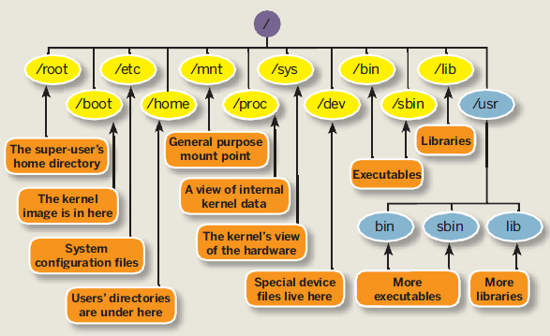
Directory Structure
of
Raspberry Pi running
Soft-float
Debian “wheezy”
I have created an overview directory maps of my Raspberry Pi directory
map to assist me in understanding the files modification that I will be
dealing with.
Learning how things are being organised in a Linux platform. |
/~–/bin Essential
commands that all user
|
|-/boot Information
that boots the machine, including Kernel.
| |-boot.rc
|
|-/dev Device
driver for all the hardware peripherals.
| |-/block
| |-/bus
| |-/char
| |-/disk
| |-/input
| |-/mapper
| |-/net
| |-/pts
| |-/raw
| |-/snd
|-/etc Configuration
files for your system.
| |-/alternatives
| |-/apm
| |-/apparmor.d
| |-/apt
| |-/avahi
| |-/bash_completion.d
| |-/ca-certificates
| |-/calendar
| |-/console-setup
| |-/ConsoleKit
| |-/cron.d
| |-/cron.daily
| |-/cron.hourly
| |-/cron.monthly
| |-/cron.weekly
| |-/dbus-1
| |-/default
| |-/dhcp
| |-/dhcp3
| |-/dictionaries-common
| |-/dillo
| |-/dpkg
| |-/emacs
| |-/fonts
| |-/fstab.d
| |-/gconf
| |-/gdb
| |-/ghostscript
| |-/groff
| |-/gtk-2.0
| |-/gtk-3.0
| |-/ifplugd
| |-/init
| |-/init.d save
and register scripts in this directory to auto run when bootup or
shutdown
| |-/insserv
| |-/insserv.conf.d
| |-/iproute2
| |-/kbd
| |-/ld.so.conf.d
| |-/ldap
| |-/libnl-3
| |-/libpaper.d
| |-/lightdm
| |-/logcheck
| |-/logrotate.d
| |-/menu
| |-/menu-methods
| |-/modprobe.d
| |-/network
| |-/opt
| |-/pam.d
| |-/perl
| |-/pm
| |-/polkit-1
| |-/profile.d
| |-/pulse
| |-/python
| |-/python2.7
| |-/python3
| |-/python3.2
| |-/rc0.d
| |-/rc1.d
| |-/rc2.d
| |-/rc3.d
| |-/rc4.d
| |-/rc5.d
| |-/rc6.d
| |-/rcS.d
| |-/request-key.d
| |-/rsyslog.d
| |-/samba
| |-/security
| |-/selinux
| |-/sgml
| |-/skel
| |-/ssh
| |-/ssl
| |-/sudoers.d
| |-/sysctl.d
| |-/systemd
| |-/terminfo
| |-/triggerhappy
| |-/udev
| |-/ufw
| |-/vim
| |-/wpa_supplicant
| |-/X11
| |-/xdg
| |-/xml
| |-/xpdf
| |-inittab controls the startup/initialization process (example: auto login)
| |-profile
| |-rc.local
|
|-/home Home directory
for each of the user
| |~/pi (User
named pi)
| |-/Desktop
| |-/python_games
| |-.bashrc script
trigger everytime a specific user logs in
|
|-/lib Library
or code, Kernel or other programs use.
| |-/arm-linux-gnueabi
| |-/firmware
| |-/init
| |-/lsb
| |-/modprobe.d
| |-/modules
| |-/systemd
| |-/terminfo
| |-/udev
| |-/xtables
|
|-/lost+found
|
|-/media Temp media (disk,
CD-ROM)
|
|-/mnt Temp
media (disk, CD-ROM, network drive)
|
|-/opt Location
for installing new software package.
| |-/java
| |-/pi4j
| |-/vc
|
|-/proc
|
|-/root Super user’s
home directory
|
|-/run
| |-/ConsoleKit
| |-/dbus
| |-/lock
| |-/mount
| |-/network
| |-/sendsigs.omit.d
| |-/shm
| |-/sshd
| |-/udev
|
|-/sbin Commands
for system adminstrator.
|
|-/selinux
|
|-/srv Data
for system’s services (programs running in the background)
|
|-/sys
| |-/block
| |-/bus
| |-/class
| |-/dev
| |-/devices
| |-/firmware
| |-/fs
| |-/kernel
| |-/module
| |-/power
|
|-/tmp for
storing temp files
|
|-/usr A
complex hierarchy of additional programs and files
| |-/bin
| |-/games
| |-/include
| |-/lib
| |-/local
| |-/sbin
| |-/share
| |-/src
|
|-/var The
data that changes frequently. (log files, emails)
| |-/backups
| |-/cache
| |-/lib
| |-/local
| |-/log
| |-/mail
| |-/opt
| |-/spool
| |-/tmp
|
Linux
Files and Directory Structure Reference
|
/~–/bin Essential
commands that all user
|
|-/boot Information
that boots the machine, including Kernel.
|
|-/dev Device
driver for all the hardware peripherals.
| |-/cd-rom
| |-/fd0
| |-/fd1
| |-/hda
| |-/hda1
| |-/hda2
| |-/hdb
| |-/hdb1
| |-/hdb2
| |-/sda
| |-/sda1
|
|-/etc Configuration
files for your system.
|
|-/home Home directory
for each of the user
| |~/pi (User
named pi)
| |-/Desktop
|
|-/lib Library
or code, Kernel or other programs use.
|
|-/media Temp media (disk,
CD-ROM)
|
|-/mnt Temp
media (disk, CD-ROM, network drive)
|
|-/opt Location
for installing new software package.
|
|-/root Super user’s
home directory
|
|-/sbin Commands
for system adminstrator.
|
|-/srv Data
for system’s services (programs running in the background)
|
|-/tmp for
storing temp files
|
|-/usr A
complex hierarchy of additional programs and files
| |-/X11R6
| |-/bin
| |-/games
| |-/include
| |-/lib
| |-/local
| |-/sbin
| |-/share
| |-/src
|
|-/var The
data that changes frequently. (log files, emails)
-/??? -> Directory related to the Linux operating
system that needs careful attention in handling. |
Linux
Command Reference
– linux_quickref.pdf
– linuxcard.pdf |
|
| |
| |


 raspberrypi
login: pi
raspberrypi
login: pi


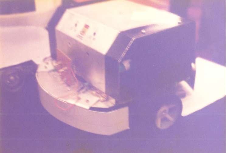
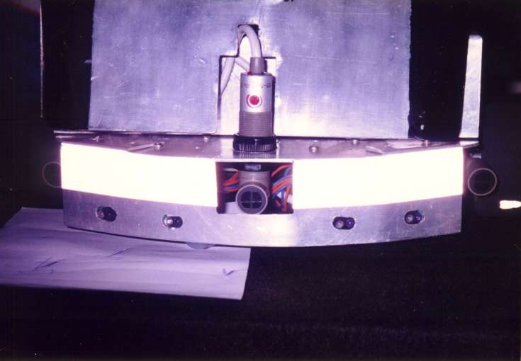
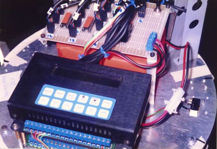

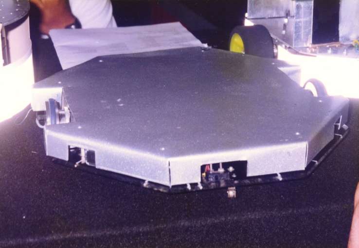

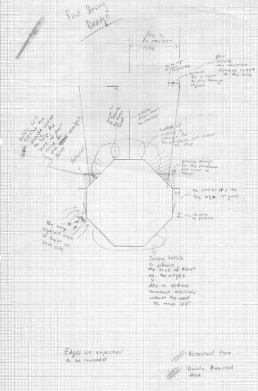
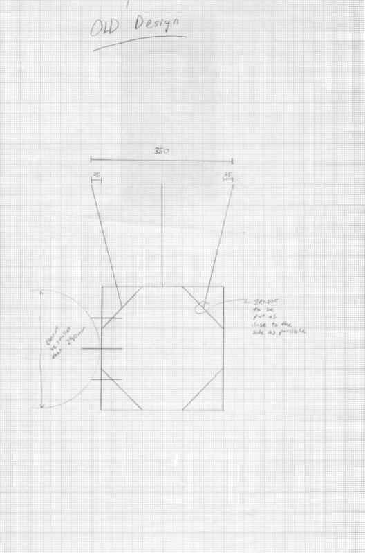
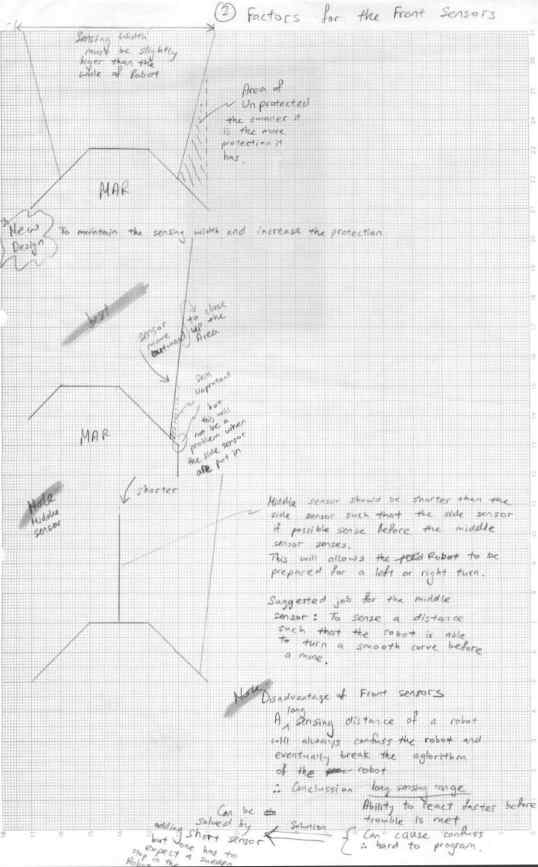
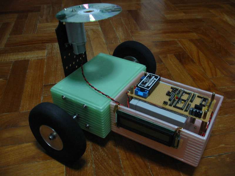
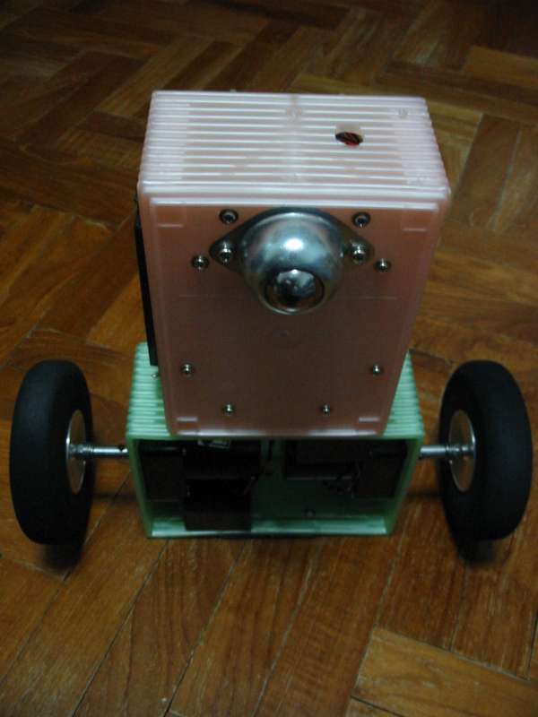
 This
is one of the robot using ultra sonic sensing. The sensor is enclose
behind the casing. We are very aware that only this type of sensor at
that time, can be mounted in this manner. We were trying very hard to
analysis all possible threat for Robot Battlefield 1998.
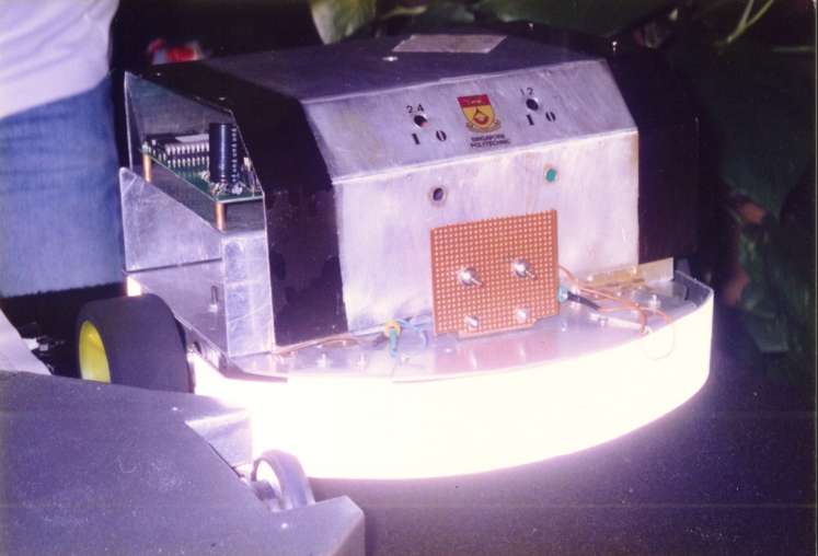
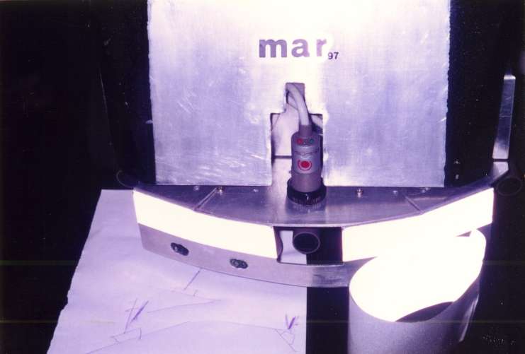
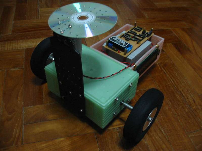
This
is one of the robot using ultra sonic sensing. The sensor is enclose
behind the casing. We are very aware that only this type of sensor at
that time, can be mounted in this manner. We were trying very hard to
analysis all possible threat for Robot Battlefield 1998.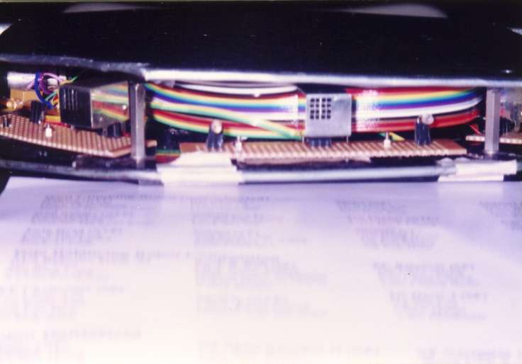


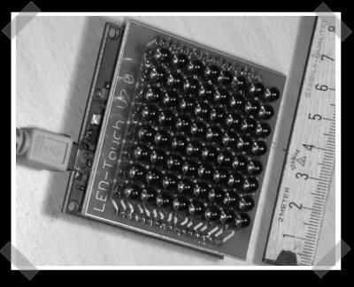
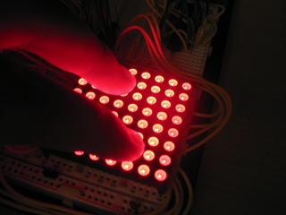
 Resistive touch sensor is
commonly deployed in our touch panel LCD monitor.
Resistive touch sensor is
commonly deployed in our touch panel LCD monitor.

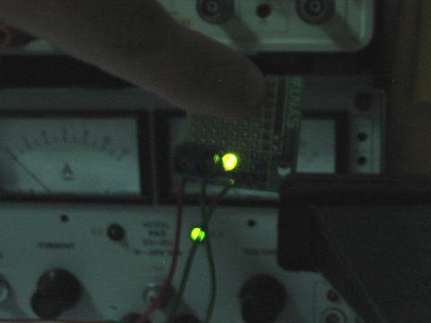
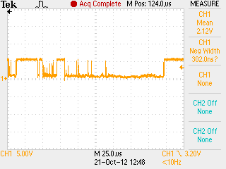
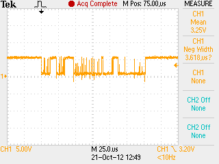
 Acroustic sound sensing, by sensitive object.


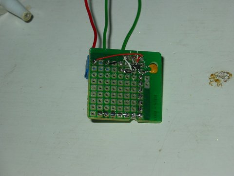


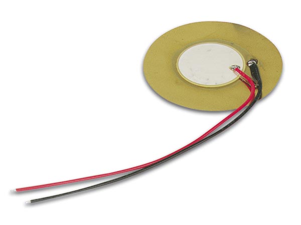


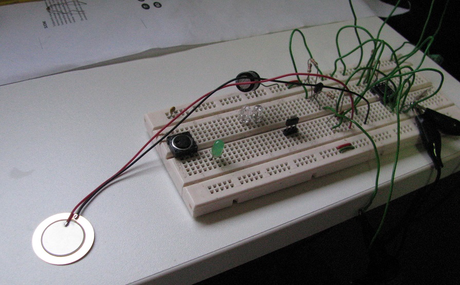
 ceramic back side of the plate.
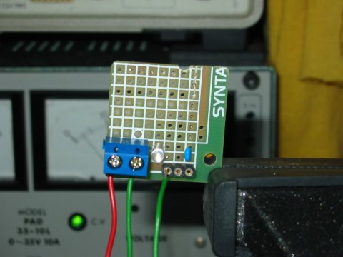
  front side of the plate.
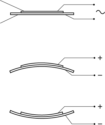
  side view showing the piezo, a very thin
plate.
side view showing the piezo, a very thin
plate.