Get started with Raspberry Pi (RPi), a step by step approach to get your Raspberry Pi with low level electronics hardware control.
Make simple, step by step.
- Edited by Lim Siong Boon, last dated 22-Sep-2013.
Topic Discussion Overview
- Installation from scratch
- Hardware Pin Out
- Raspberry Pi, HelloWorld for I/O pins
- Understanding UART, SPI, I2C port on Raspberry Pi
- Networking on Raspberry Pi
- Accessing Raspberry Pi through the network
- C Programming
- Python Programming
- Java Programming
- List of frequent used Commands
- Add Wifi to Raspberry Pi
| 1. Installation from scratch |
|
|
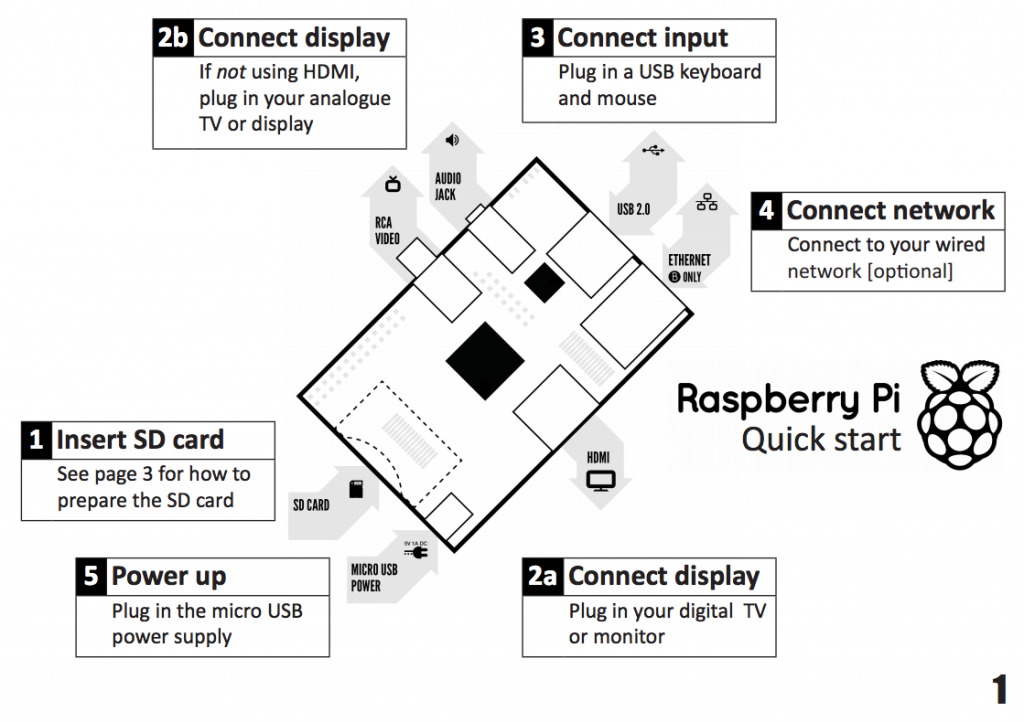
Your orientation to Raspberry Pi.
|
Status
LED Indicator |
|
STEP 01: Download this quick start up guide to help you install your Linux OS on your Raspberry Pi. |
 |
|
STEP 02:
Get yourself a 4GB SD card, which is enough for use in many application. |
|
|
STEP 03: Format
your SD card with SD
Formatter 4.0 for SD/SDHC/SDXC
|
|
|
STEP 04: You can
download the image version New Out Of Box
Software (NOOBS), extract all the files and copy into your SD
card. |
|
|
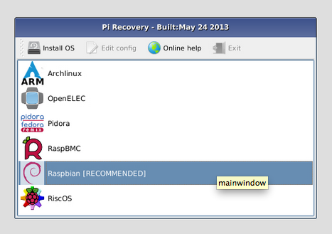
STEP 05: You will be ask
to select an Linux OS to install on your Raspberry Pi.
Proceed to step 10. |
Installing Raspbian operating system onto my Raspberry Pi.
|
|
|
|
|
STEP 06: As of 02 Nov 2013, Raspbian now supports and pre-installed with Java.
|
|
|
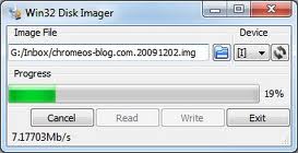
STEP 07: Download
and run the Win32DiskImager
on your Windows Operating System. |
|
|
STEP 08: Unzip
the Debian Linux version Soft-float
Debian “wheezy”, which is a “2013-05-29-wheezy-armel.img”
file. |
 |
|
STEP 09: Insert the SD card into your Raspberry Pi and power it up. |
|
|
STEP 10: On
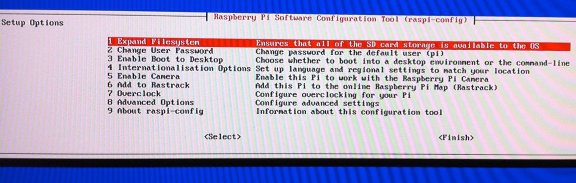
the first boot, the “raspi-config” menu will pop up.
|
“raspi-config” menu
|
Note: You may find yourself having problem when trying to key in the ‘#’ char by pressing <Shift+’3′>. A ” pound char may be generated instead. This is because the Raspberry Pi’s default locale code is set as UK. You will need to set the locale code to US, for a US keyboard layout. Key
in the following command,
Alternative
method to configure you keyboard layout. | |
STEP 11: Select
<1> and press enter to Expand Filesystem. <A4 SSH> to enable or disable SSH (remote command access); it is enable by default. <A5 Update> and then press enter to upgrade to the latest version of this tool. Try to perform this update. | “raspi-config” menu 8-A
|
To change to the Standard US Keyboard mapping, select <4
Internationalisation Options>, |
“raspi-config” menu 4-I
|
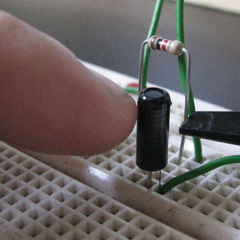
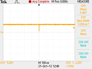
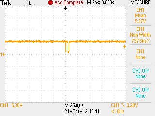
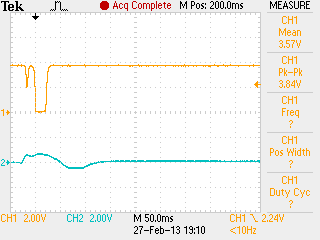
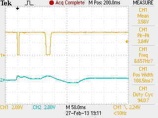
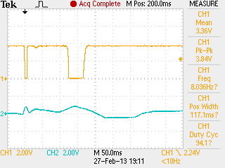
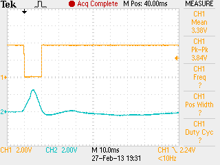
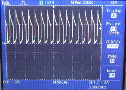
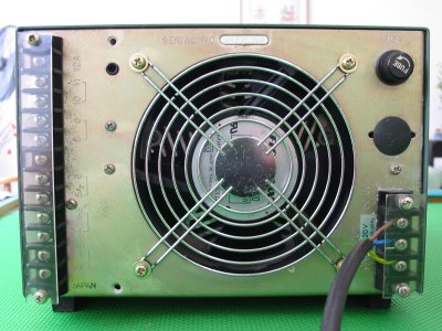
| Very Very Important Note regarding boot up error If you have encounter any error during the Linux operating system boot up, be sure to check the voltage level being supplied to your Raspberry Pi. It is a very common problem faced, if you have tried to power up your Raspberry Pi using any power adaptor that you have picked up. Always check if your power adaptor is suitable by measuring the voltage supplied to your Raspberry Pi. If you deploy your Raspberry Pi for yoru project without ensuring that your power adaptor is ok, you may face random system error freeze/hang/halt. Problem can occur out of the norm. Be sure to check. Click here to find out how you can ensure that you are using the correct power adaptor and cable for your Raspberry Pi. |
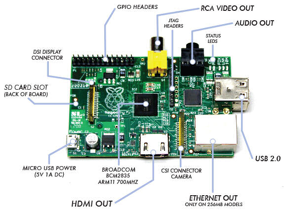


| 2. Hardware Pin Out |
|
||||||||||||||||||||||||||||||||||||||||||||||||||||||||||||||||||||||||||||||
|
Raspberry Pi revision 2, header pins out.
|
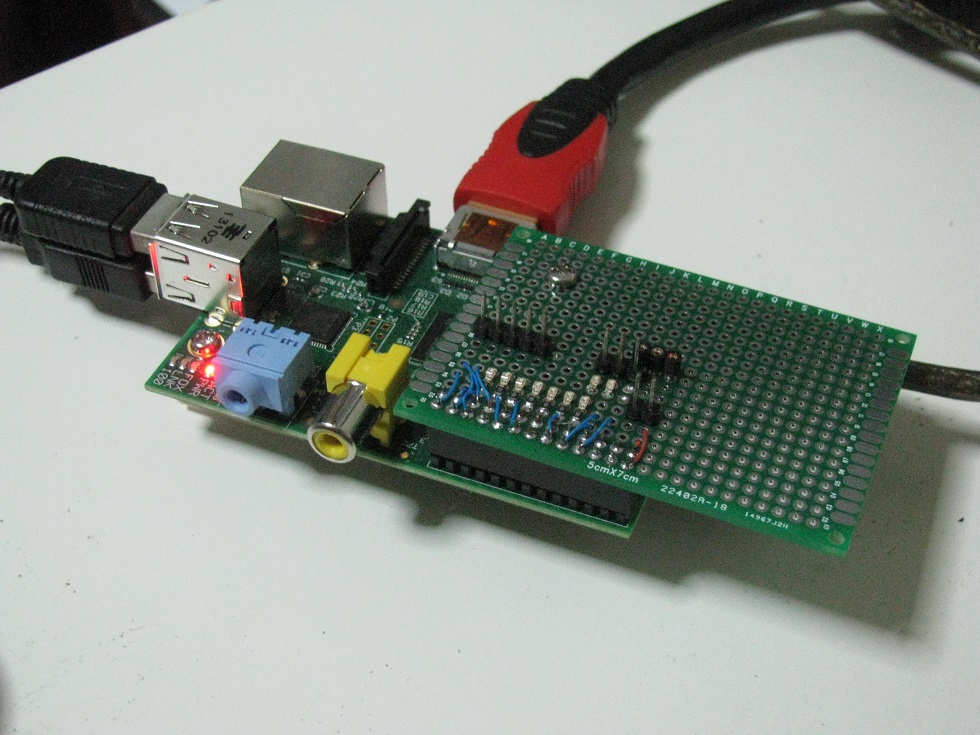
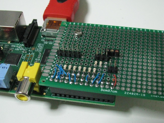
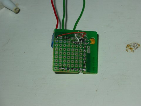
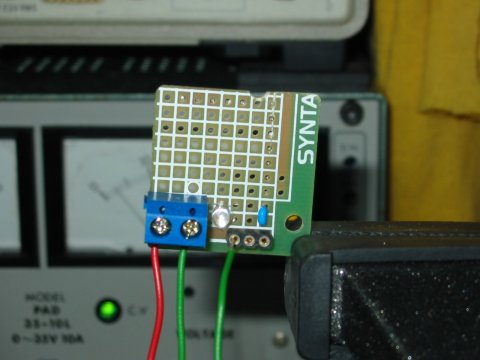
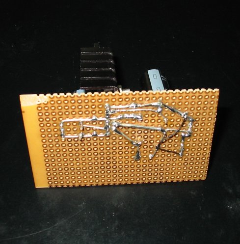
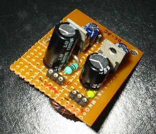
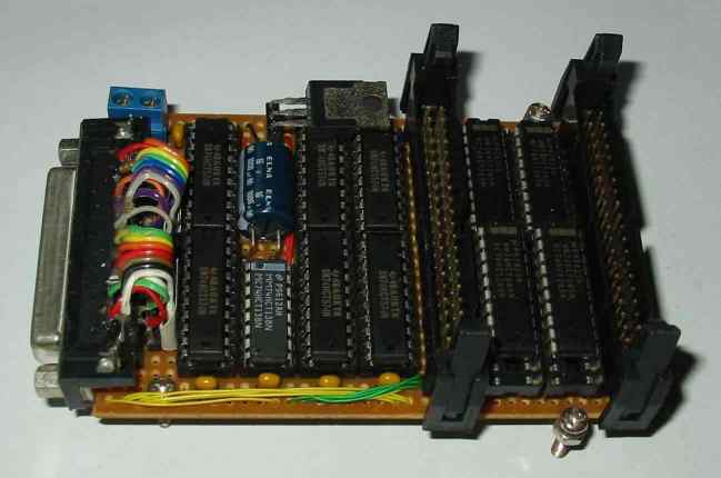
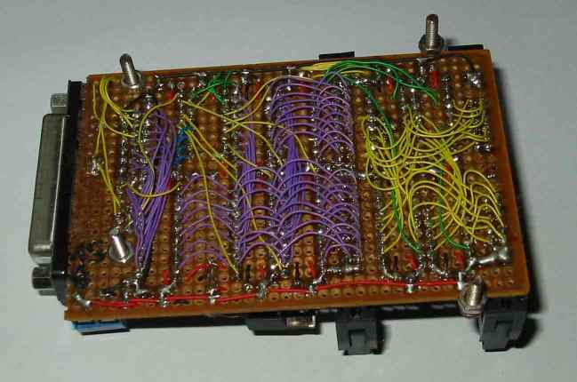
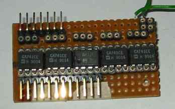
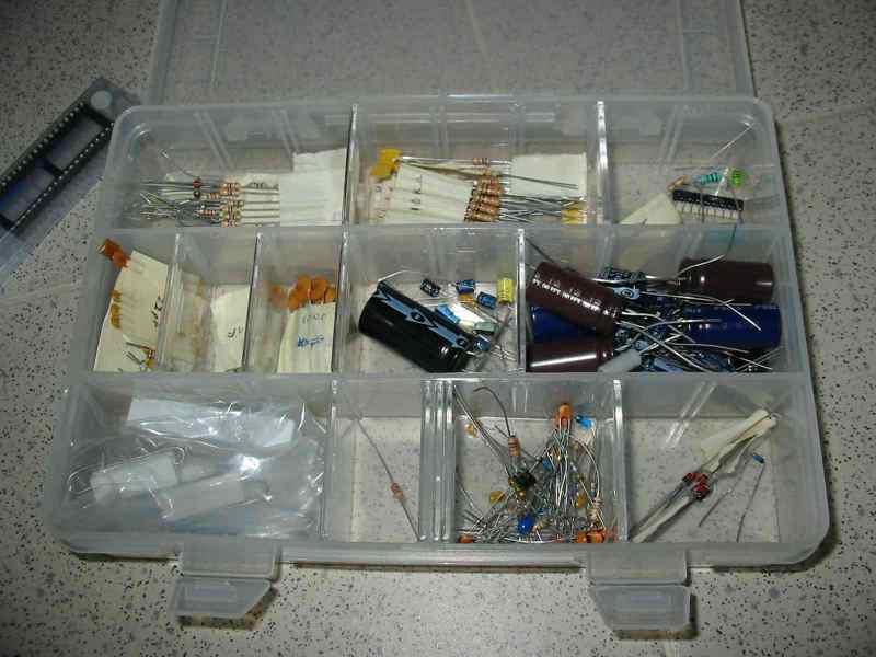
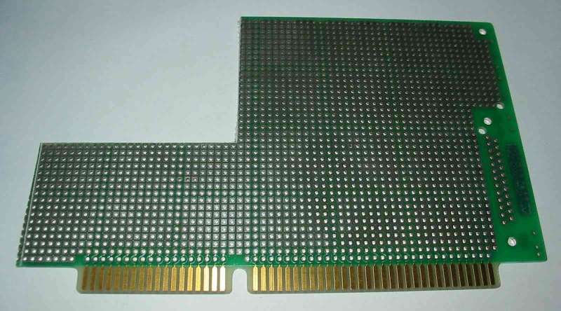
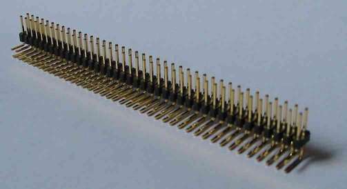
This
is my Raspberry Pi. I have custom built a prototyping board that can be
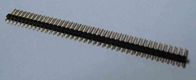
plugged on top of my Raspberry Pi. This prototyping board is soldered
with 2.54mm housing connector (2 rows of 13 pins) so that I can easily
access to the I/O pins of my Raspberry Pi. My
LED indicator wiring is as follows, |
||||||||||||||||||||||||||||||||||||||||||||||||||||||||||||||||||||||||||||||
Information taken from |
|
||||||||||||||||||||||||||||||||||||||||||||||||||||||||||||||||||||||||||||||
| 3. Raspberry Pi, HelloWorld for I/O pins | |
|
Learning to control Raspberry Pi general purpose I/O pin 11 (which is known as GPIO_0, or GPIO_17 if base on BCM2835 IC pin assignment)Power on my Raspberry, and the operating system will prompt for my raspberrypi login.Key in “pi” for the login, and “raspberry” for the password.
|
pi@raspberrypi ~ $ |
| First start by keying the command “” to change to the root user, which have a higher privilege access rights to the system. | pi@raspberrypi ~ $ sudo -i |
| You will see a new prompt -> | root@raspberrypi:~# |
|
Setup or initialise I/O port 17, by sending text “17” to the operating file system “/sys/class/gpio/export” A directory folder will be created. “/sys/class/gpio/gpio17/” |
root@raspberrypi:~# echo “17” > /sys/class/gpio/export |
| Setting the I/O pin as an output port, by sending text “out” to the operating file system “/sys/class/gpio/gpio17/direction” | root@raspberrypi:~# echo “out” > /sys/class/gpio/gpio17/direction |
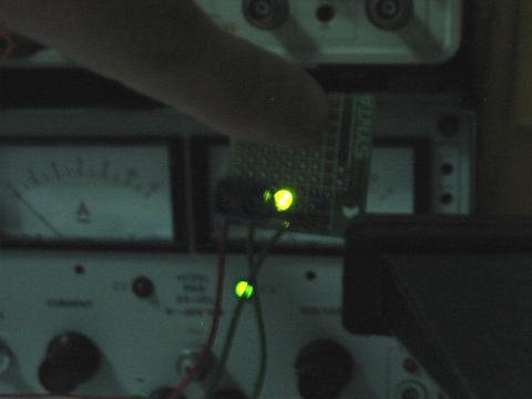
| To set logic 1 to the output port, send a text “1” to the operating file system “/sys/class/gpio/gpio17/value” | root@raspberrypi:~# echo “1” > /sys/class/gpio/gpio17/value |
| My LED indicator0 (green color) gets lighted up. My very first hardware control using Raspberry Pi, Linux operating system. Yuppee… | 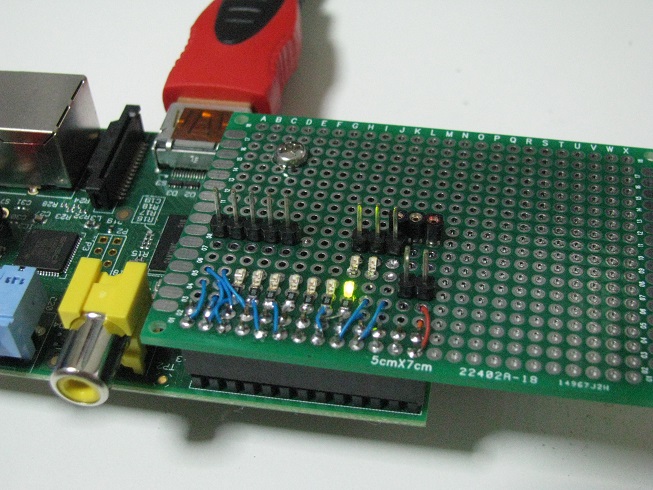 |
| To switch off my LED, send a text “0” to the operating file system “/sys/class/gpio/gpio17/value” | root@raspberrypi:~# echo “0” > /sys/class/gpio/gpio17/value |
| Setting up an input port is quite similar. I will be using I/O port 18 as input. | |
| Setup I/O port 18. | root@raspberrypi:~# echo “18” > /sys/class/gpio/export |
| Setup port 18 as an input port. | root@raspberrypi:~# echo “in” > /sys/class/gpio/gpio18/direction |
| Reading input port 18. | root@raspberrypi:~# cat /sys/class/gpio/gpio18/value |
| Command prompt will return the following value (logic 0) after reading the port. | 0 root@raspberrypi:~# |
| The port 18, which is pin 12 on my Raspberry Pi is now connected to 3.3V to simulate a logic 1 input. The input port is then rRead in again. | root@raspberrypi:~# cat /sys/class/gpio/gpio18/value |
| Command prompt will return the following value (logic 1) after reading the port, which is correct. | 1 root@raspberrypi:~# |
|
Reference:
|
|
|
I am able to control the I/O pins on my Raspberry Pi, but I want to larn more into controlling the I/O pins using native C. Controlling I/O pins using the “file directory system” like method will be very slow.The speed achieved base on this benchmark website, I/O control through this shell (or file directory system) method, achieved a maximum process speed of about 6.8kHz (2x 3.4kHz).To achieve a higher speed, I will need to use native C programming, which can process from 9.4Mhz to 44Mhz (2x 4.7Mhz to 22Mhz). More things to learn… |
|
|
References: Notes regarding digital I/O pins, https://www.kernel.org/doc/Documentation/gpio.txt |
 raspberrypi
login: pi
raspberrypi
login: pi
| 4. Understanding UART, SPI, I2C port on Raspberry Pi | |
|
UART The
UART port is actually pin8 (TxD) and pin10 (RxD) on the Raspberry Pi
connectors. The UART signal is 3.3V.You can use
RS232/RS422/RS485 communication to talk to the UART, but a level
shifter (for example MAX3232) required. RS232 uses about +/- 7 to 13V,
while UART uses digital voltage (1.8V, 3.3V or 5V). For our Raspberry
Pi UART, it is 3.3V. More information about making your own level
shifter, you can visit this
page. There are also standard USB to UART products for
interfacing to your Raspberry Pi.The Raspberry Pi
default operating system uses this UART port as its diagnostic port.
This port has the following default UART settings,
|
|
|
You can use a terminal program to access through this port.Using the Window’s Hyperterminal program, setup the correct com port settings. And connect the terminal. You will see nothing on the terminal screen, but actually the Raspberry Pi is prompting you for your login ID. This ID is “pi” which is similar to how you log on to your typical terminal screen. You will see the terminal replying you with the prompt for password. Key in the default password “raspberry”. You shall get a similar print out from the terminal program, as on the right. ->Looks very much like the typical terminal on your local display. This is mainly for troubleshooting, diagnostic or perhaps used for remote access of your Raspberry Pi.
|
raspberrypi
login: pi Debian
GNU/Linux comes with ABSOLUTELY NO WARRANTY, to the extent |
|
The UART on the Raspberry Pi is quite an useful peripheral. For me, I would like to use this UART as a serial communication to control my other circuit modular. In order to use this UART, I need to disable the diagnostic features from the operating system’s boot up. This means that I do not want the system to setup the UART pins as diagnotic port, when the system boots up. |
|
| This means that we need to edit the boot up file. Before we do any editing, it is good to save a backup copy of it. Type the copy command “cp” as follows. -> | pi@raspberrypi ~ $ sudo cp /boot/cmdline.txt /boot/cmdline_backup.txt |
|
The
following command is key in to edit the system boot up script. vi is an
text editor program, which is not very user friendly.Alternative, you can
use nano editor instead of vi for the
text file editing. A summary of the vi editor’s command is summeries as follows, http://osr600doc.sco.com/en/FD_create/vi_summary.html |
pi@raspberrypi ~ $ sudo vi /boot/cmdline.txt |
|
After the vi command, you should see the following screen display. This is the vi editor diaplaying the text in the “cmdline.txt file”.The objective is to delete the text (in red color), which is relating to the UART setup. Press ‘l’ on your keyboard to shift the cursor to the right, until it is at the position of the char that we want to delete. Move the cursor under the first char ‘c’ (char as illustrated in red).Press ‘x’ on your keyboard to delete the char one by one. You should observed the delete action.When all the text in red are deleted, press ‘:w’ on your keyboard, follow by a enter key to save the text file.Press ‘:q’ on your keyboard, follow by a enter key to exit the vi program.If at anytime you have edit wrongly, you can enter the command ‘:q!’ on your keyboard, to exit the vi program without saving the text file.
|
dwc_otg.lpm_enable=0 console=ttyAMA0,115200 kgdboc=ttyAMA0,115200
console=tty1 root=/dev/mmcblk0p2 rootfstype=ext4 elevator=deadline
rootwait |
| Your “cmdline.txt” should contain the following text after the editing. | dwc_otg.lpm_enable=0 console=tty1 root=/dev/mmcblk0p2 rootfstype=ext4 elevator=deadline rootwait ~ ~ ~ |
| Next edit inittab with the following command. | pi@raspberrypi ~ $ sudo vi /etc/inittab |
|
Find
and comment away the line containing the following text (near the end of the file), Press ‘:q’ to exit the vi program. |
#Spawn a getty on Raspberry Pi serial line #T0:23:respawn:/sbin/getty -L ttyAMA0 115200 vt100 |
|
The
UART device name is /dev/ttyAMA0
|
|
| Reboot for the operating system’s settings to take effect. | pi@raspberrypi ~ $ sudo reboot |
|
To
test the UART serial communication port, we can install a program call minicom.
The use of minicom is similar to hyperterminal
program that I use in Windows operating system (OS). |
pi@raspberrypi
~ $ sudo apt-get install minicom Reading package lists… Done Building dependency tree Reading state information… Done … Need to get 420 kB of archives. After this operation, 1,189 kB of additional disk space will be used. Do you want to continue [Y/n]? y Get:1 http://mirrordirector.raspbian.org/raspbian/ wheezy/main lrzsz armhf 0.12.21-5 [106 kB] Get:2 http://mirrordirector.raspbian.org/raspbian/ wheezy/main minicom armhf 2.6.1-1 [314 kB] Fetched 420 kB in 13s (30.2 kB/s) … Unpacking minicom (from …/minicom_2.6.1-1_armhf.deb) … Processing triggers for man-db … Processing triggers for menu … Setting up lrzsz (0.12.21-5) … Setting up minicom (2.6.1-1) … Processing triggers for menu … |
|
To
run the minicom terminal program. Key in the following command “sudo
minicom -b 9600 -o -D /dev/ttyAMA0“. |
pi@raspberrypi
~ $ sudo minicom -b 9600 -o -D /dev/ttyAMA0 CTRL-A Z for help |
9600 8N1 | NOR | Minicom 2.6.1 | VT102 | Offline |
|
Setting up the serial
port with other settings, |
pi@raspberrypi ~ $ sudo minicom -b 115200 -8 -o -D /dev/ttyAMA0 |
| Key in command “sudo
minicom -s ” to launch the minicom menu for other default settings,
which can be save onto *.dfl files. The default config file is minicom.dfl |
|
| Other related commands – “dmesg | grep tty” checking up the UART available on the system. |
|
SPI The SPI port onboard the Raspberry is disable by default. The first thing to do is to enable the SPI port. Edit the file “/etc/modprobe.d/raspi-blacklist.conf” Comment off the line “blacklist spi-bcm2708” with a # in front. Key in Ctrl+’X’ to exit, then ‘Y’ yes to save the change to the file, and finally ‘Enter’. This will brings you back to the command prompt. |
pi@raspberrypi ~ $ sudo nano /etc/modprobe.d/raspi-blacklist.conf GNU nano 2.2.6 File: /etc/modprobe.d/raspi-blacklist.conf Modified # blacklist spi and i2c by default (many users don’t need them) #blacklist spi-bcm2708
|
| Reboot Raspberry Pi | pi@raspberrypi ~ $ sudo reboot |
Check to see if the SPI is successfully enable in the Raspberry Pi. You should see “/dev/spidev0.0 /dev/spidev0.1” created. 0.0 means SPI0 CS0 (CS is the chip select) |
pi@raspberrypi ~ $ ls /dev/spidev* |
Testing the SPI port download this SPI loopback test code written in ‘C’ programming language. Compile the *.c file using gcc command,then run the compiled program. You should see the following hex dump data, indicating all 0x00. This means that the SPI is receiving nothing, no data. |
pi@raspberrypi ~ $ gcc spidev_test.c -o spidev_test 00 00 00 00 00 00 |
Now we do a SPI data loopback test. From this test, we will be able to know if SPI hardware for sending and receving is working ok. Whatever that is sent out, the data should be properly received. Run the compiled program again. You should see the following hex dump data. This means that your SPI peripheral is working fine. |
pi@raspberrypi ~ $ sudo ./spidev_test -D /dev/spidev0.0 spi mode: 0 FF FF FF FF FF FF |
I2C The SPI port onboard the Raspberry is disable by default. The first thing to do is to enable the SPI port. Edit the file “/etc/modprobe.d/raspi-blacklist.conf” Comment off the line “blacklist i2c-bcm2708” with a # in front. Key in Ctrl+’X’ to exit, then ‘Y’ yes to save the change to the file, and finally ‘Enter’. This will brings you back to the command prompt. |
pi@raspberrypi ~ $ sudo nano /etc/modprobe.d/raspi-blacklist.conf GNU nano 2.2.6 File: /etc/modprobe.d/raspi-blacklist.conf Modified # blacklist spi and i2c by default (many users don’t need them) blacklist spi-bcm2708
|
Edit the file “/etc/modules” Add in “i2c-dev” to the end of the file. Key in Ctrl+’X’ to exit, then ‘Y’ yes to save the change to the file, and finally ‘Enter’. This will brings you back to the command prompt. |
pi@raspberrypi ~ $ sudo nano /etc/modules # /etc/modules: kernel modules to load at boot time. snd-bcm2835
|
| Install I2C Tools to test on the I2C peripheral. | pi@raspberrypi ~ $ sudo apt-get install i2c-tools Reading package lists… Done Building dependency tree Reading state information… Done Suggested packages: libi2c-dev python-smbus The following NEW packages will be installed: i2c-tools 0 upgraded, 1 newly installed, 0 to remove and 52 not upgraded. Need to get 59.5 kB of archives. After this operation, 223 kB of additional disk space will be used. Get:1 http://http.debian.net/debian/ wheezy/main i2c-tools armel 3.1.0-2 [59.5 kB] Fetched 59.5 kB in 4s (12.5 kB/s) Selecting previously unselected package i2c-tools. (Reading database … 57047 files and directories currently installed.) Unpacking i2c-tools (from …/i2c-tools_3.1.0-2_armel.deb) … Processing triggers for man-db … Setting up i2c-tools (3.1.0-2) … |
Allow Pi User to Access I2C peripheral. This allow configuration of the software. |
pi@raspberrypi ~ $ sudo adduser pi i2c Adding user `pi’ to group `i2c’ … Adding user pi to group i2c Done. |
| Reboot Raspberry Pi | pi@raspberrypi ~ $ sudo reboot |
Check to see if the SPI is successfully enable in the Raspberry Pi. You should see “/dev/i2c-0 /dev/i2c-1” created. |
pi@raspberrypi ~ $ ls /dev/i2c* |
Running the test program. You will see that there is a total of 0x77 or 119 blanks “–“. This indicates that no I2C devices is detected on the bus. |
pi@raspberrypi ~ $ i2cdetect -y 0 0 1 2 3 4 5 6 7 8 9 a b c d e f 00: — — — — — — — — — — — — — — — — 10: — — — — — — — — — — — — — — — — 20: — — — — — — — — — — — — — — — — 30: — — — — — — — — — — — — — — — — 40: — — — — — — — — — — — — — — — — 50: — — — — — — — — — — — — — — — — 60: — — — — — — — — — — — — — — — — 70: — — — — — — — — |
| If the I2C devices is on the I2C bus, it will appeared as follows. For this example, the I2C devices has an address of 0x60. The software detects a device is currently onto the I2C data bus. |
pi@raspberrypi ~ $ i2cdetect -y 0 0 1 2 3 4 5 6 7 8 9 a b c d e f 00: — — — — — — — — — — — — — — — — 10: — — — — — — — — — — — — — — — — 20: — — — — — — — — — — — — — — — — 30: — — — — — — — — — — — — — — — — 40: — — — — — — — — — — — — — — — — 50: — — — — — — — — — — — — — — — — 60: 60 — — — — — — — — — — — — — — — 70: — — — — — — — — |

| 5. Networking on Raspberry Pi | References: – Installing Samba program |
| Checking the IP setting on my Raspberry Pi. | pi@raspberrypi |
| Ping gateway 192.168.1.1 | pi@raspberrypi ping
192.168.1.1 -c 4 PING 192.168.1.1 (192.168.1.1) 56(84) bytes of data. 64 bytes from 192.168.1.1: icmp_seq=1 ttl=64 time=1.98 ms 64 bytes from 192.168.1.1: icmp_seq=2 ttl=64 time=1.17 ms 64 bytes from 192.168.1.1: icmp_seq=3 ttl=64 time=1.19 ms 64 bytes from 192.168.1.1: icmp_seq=4 ttl=64 time=1.23 ms — 192.168.1.1 ping statistics — 4 packets transmitted, 4 packets received, 0% packet loss, time 3004ms rtt min/avg/max/mdev = 1.171/1.399/1.988/0.340 ms |
| Ping website www.yahoo.com.sg | pi@raspberrypi ~ $ ping
yahoo.com.sg -c 4 PING yahoo.com.sg (106.10.165.51) 56(84) bytes of data. 64 bytes from w2.rc.vip.sg3.yahoo.com (106.10.165.51): icmp_seq=1 ttl=51 time=16.9 ms 64 bytes from w2.rc.vip.sg3.yahoo.com (106.10.165.51): icmp_seq=2 ttl=51 time=28.1 ms 64 bytes from w2.rc.vip.sg3.yahoo.com (106.10.165.51): icmp_seq=3 ttl=51 time=20.3 ms 64 bytes from w2.rc.vip.sg3.yahoo.com (106.10.165.51): icmp_seq=4 ttl=51 time=17.5 ms — yahoo.com.sg ping statistics — 4 packets transmitted, 4 packets received, 0% packet loss, time 3004ms rtt min/avg/max/mdev = 16.996/20.762/28.140/4.441 ms |
|
Other
command: |
|
|
Install Samba on the system so that my Raspberry Pi can be access from a Window operating system. Ensure that the network cable (internet enabled) is plugged onto the Raspberry Pi before powering on the board. Enter the following command to install samba software. The process will fetch the installation from the internet. |
pi@raspberrypi
~ $
sudo
apt-get install samba samba-common-bin |
| Optional: Enable security on the Samba server on the Raspberry Pi (RPi) |
|
| Making a backup of the samba configuration file. | pi@raspberrypi ~ $ sudo cp /etc/samba/smb.conf /etc/samba/smb.conf.old |
| Edit the samba configuration file using the nano text editor | pi@raspberrypi ~ $ sudo nano /etc/samba/smb.conf |
|
Search
for the section marked ##### Authentication #####, |
|
| Restart samba to use the new configuration file. | pi@raspberrypi
~ $ sudo /etc/init.d/samba restart [ ok ] Stopping Samba daemons: nmdb smdb [ ok ] Stopping Samba daemons: nmdb smdb |
|
Use command “hostname -I” to check the IP address. Alternate command “ifconfig” to check the IP address of my Raspberry Pi, which IP address is “192.168.1.99” |
pi@raspberrypi
~ $
hostname -I pi@raspberrypi
~ $
ifconfig |
| Or using command “ip address show” | pi@raspberrypi
~ $
ip
address show 1: lo: <LOOPBACK,UP,LOWER_UP> mtu 16436 qdisc noqueue state UNKNOWN link/loopback 00:00:00:00:00:00 brd 00:00:00:00:00:00 inet 127.0.0.1/8 scope host lo 2: eth0: <BROADCAST,MULTICAST,UP,LOWER_UP> mtu 1500 qdisc pfifo_fast state UP qlen 1000 link/ether b8:27:eb:dc:ee:af brd ff:ff:ff:ff:ff:ff inet 192.168.1.95/24 brd 192.168.1.255 scope global eth0 |
| Configuring
your network settings
sudo nano /etc/network/interfaces |
pi@raspberrypi
~ $ sudo nano /etc/network/interfaces auto lo iface lo inet loopback iface eth0 inet dhcp allow-hotplug wlan0 iface wlan0 inet manual wpa-roam /etc/wpa_supplicant/wpa_supplicant.conf iface default inet dhcp |
| To set static IP address, edit the file “interfaces” to the example as follows. Save the file and reboot Raspberry Pi for the changes to take effect. |
auto lo iface lo inet loopback #wired connection (using static IP address, instead of DHCP to auto allocate IP) #iface eth0 inet dhcp iface eth0 inet static address 192.168.1.201 netmask 255.255.255.0 gateway 192.168.1.1 #wireless connection (using static IP address, instead of DHCP to auto allocate IP) allow-hotplug wlan0 iface wlan0 inet manual wpa-roam /etc/wpa_supplicant/wpa_supplicant.conf #iface wlan0 inet dhcp iface wlan0 inet static address 192.168.1.202 netmask 255.255.255.0 gateway 192.168.1.1 #iface default inet dhcp |
|
Go to window’s to map a network drive. The network folder path is “//192.168.1.99”. Check box for “Reconnect at logon” & “Connect using different credentials” |
|
Check the network and port bind on the Raspberry Pi.
From the list, it can be seen that UDP port 6324 is currently being used by process ID PID 2361/java program. |
pi@raspberrypi ~ $ netstat -nlptu (Not all processes could be identified, non-owned process info will not be shown, you would have to be root to see it all.) Active Internet connections (only servers) Proto Recv-Q Send-Q Local Address Foreign Address State PID/Program name tcp 0 0 127.0.0.1:6010 0.0.0.0:* LISTEN – tcp 0 0 0.0.0.0:22 0.0.0.0:* LISTEN – udp 0 0 192.168.1.99:123 0.0.0.0:* – udp 0 0 127.0.0.1:123 0.0.0.0:* – udp 0 0 0.0.0.0:123 0.0.0.0:* – udp 0 0 0.0.0.0:51876 0.0.0.0:* – udp 0 0 0.0.0.0:6324 0.0.0.0:* 2361/java udp 0 0 0.0.0.0:68 0.0.0.0:* – |
| Setting up a secure home Web Server with Raspberry Pi |
| 6. Accessing Raspberry Pi through the network |
Sometimes you may like to access to your Raspberry Pi without connecting your display monitor and your keyboard. This section provide a guide to allow access to your Raspberry Pi remotely through network connection.
|
| Checking the IP setting on the Raspberry Pi, using command “ip address show”. For my Raspberry Pi, the IP address is 192.168.1.95. | pi@raspberrypi
~ $ ip
address show 1: lo: <LOOPBACK,UP,LOWER_UP> mtu 16436 qdisc noqueue state UNKNOWN link/loopback 00:00:00:00:00:00 brd 00:00:00:00:00:00 inet 127.0.0.1/8 scope host lo 2: eth0: <BROADCAST,MULTICAST,UP,LOWER_UP> mtu 1500 qdisc pfifo_fast state UP qlen 1000 link/ether b8:27:eb:dc:ee:af brd ff:ff:ff:ff:ff:ff inet 192.168.1.95/24 brd 192.168.1.255 scope global eth0 |
How to locate your Raspberry Pi IP address from a remote computer? The method above requires you to plugged a monitor display to your Raspberry Pi in order to obtain its IP address. The following method allows you to obtain raspberry pi address through thr You can also check the IP address of your Raspberry Pi that is plugged into a dynamic network through the router webserver. Typical router’s IP address for a local network is 192.168.1.1. You will need your user name and password to log into the router’s webserver. From the webserver, you should be able to locate the device name “raspberrypi” (or known as hostname) and its allocated dynamic IP address and its MAC address. Alternative, you can use this software “Advance Port Scanner” to scan for your Raspberry Device on the network. |
pi@raspberrypi ~ $ hostname
|
Note: To change the Raspberry Pi’s hostname “raspberrypi”, use nano text editor to edit the following file “/etc/hostname” and “/etc/hosts”. Replace the old hostname “raspberrypi” to your new hostname. Your new hostname can only contains lower/upper case character, numbers, and ‘-‘. Your new hostname will appear on the raspberry prompt, after the device reboot. |
pi@raspberrypi ~ $ sudo nano /etc/hostname pi@raspberrypi ~ $ sudo nano /etc/hosts pi@raspberrypi ~ $ sudo reboot pi@newHostname ~ $ |
|
Download
this program MobaXterm,
and install in your Window operating system. You can download from http://mobaxterm.mobatek.net/ |
|
|
Run
the installed MobaXterm program. |
|
|
Click
“OK” to connect to your Raspberry Pi. |
Login: pi Debian GNU/Linux
comes with ABSOLUTELY NO WARRANTY, to the extent |
|
You
may encounter the following error on the right. You may need to
reboot the Linux in order for the change to take effect “sudo reboot”. |
@@@@@@@@@@@@@@@@@@@@@@@@@@@@@@@@@@@@@@@@@@@@@@@@@@@@ |
| Congratulation. You have access your Raspberry Pi remotely through the network. | |
| To remotely access the desktop GUI of your Raspberry Pi, key in the following command from your MobaXterm’s command console. The ‘&’ at the end of the command help launch the application in the background (another thread process) so that we can continue using the terminal. | pi@raspberrypi ~ $ lxsession& |
| The Raspberry Pi’s desktop will be launched from your Window operating system, as follows… |  |
| GUI application can also be launched directly within WinOS without accessing to the Raspberry Pi Linux desktop. |
pi@raspberrypi ~ $ leadpad&
|
| Using MobaXterm, you can actually drag and drop file in the lower left corner of the MobaXterm’s windows. |  |
| Key in “exit”, then press enter, to terminate the session. | pi@raspberrypi ~ $ exit |
| 9. Java Programming on Raspberry Pi, Hello World!!! | |
|
Note: As of Nov 2013, the official operating system for Raspberry Pi “Raspian” is installed with Java by default. Proceed to the step for installing Pi4J. Installing Java to your Raspberry Pi First,
we will need to download and instal the Java JDK onto the Raspberry Pi.Do take note that the
JDK version that we will be downloading is meant for Linux ARM
processor “Linux ARM v6/v7 Soft Float ABI”.
|
Remember to accept the Oracle Binary Code License Agreement for Java SE. |
| Untar the Java JDK distribution file. | pi@raspberrypi
~ $ tar xvzf
~/jdk-7u21-linux-arm-sfp.tar.gz |
| Create a java
directory and move the untarred distribution to it. Delete the tar file once we are done. |
pi@raspberrypi
~ $ sudo
mkdir -p -v /opt/java pi@raspberrypi ~ $ sudo mv -v ~/jdk1.7.0_21 /opt/java/ pi@raspberrypi ~ $ rm ~/jdk-7u21-linux-arm-sfp.tar.gz |
| Create the environment paths to the java and javac commands so that they can be used anywhere in the command line environment. | pi@raspberrypi
~ $ sudo
update-alternatives –install “/usr/bin/java” “java”
“/opt/java/jdk1.7.0_21/bin/java” 1 pi@raspberrypi ~ $ sudo update-alternatives –set java /opt/java/jdk1.7.0_21/bin/java pi@raspberrypi ~ $ sudo update-alternatives –install “/usr/bin/javac” “javac” “/opt/java/jdk1.7.0_21/bin/javac” 1 pi@raspberrypi ~ $ sudo update-alternatives –set javac /opt/java/jdk1.7.0_21/bin/javac |
|
Check
that the Java environment variable is setup correctly. Note:
If the following error is encountered when the command “java -version”
is executed. |
pi@raspberrypi
~ $ java
-version java version “1.7.0_21” Java(TM) SE Runtime Environment (build 1.7.0_21-b11) Java HotSpot(TM) Client VM (build 23.21-b01, mixed mode) |
| Installing PI4J, a
bridge project between the native libraries and Java for full access to
the Raspberry Pi’s peripheral. Check out PI4J website for more information. |
pi@raspberrypi
~ $ wget
http://pi4j.googlecode.com/files/pi4j-0.0.5.deb pi@raspberrypi ~ $ sudo dpkg -i pi4j-0.0.5.deb |
|
Check
if PI4J is installed correctly. I am able to see my rows of LED lighting up in a wave sequence, up and down non-stop. |
pi@raspberrypi
~ $ cd
/opt/pi4j/examples/ |
| To uninstall PI4J, check out the following command. | pi@raspberrypi ~ $ sudo dpkg -r pi4j |
Testing out with a simple Java program. Key in “nano hello.java”. Key in the following java source code. Press ‘Ctrl+X’ to exit, then ‘Y’ to save, then press ‘Enter’. |
pi@raspberrypi ~ $ nano hello.java class hello |
Compile the java source code “hello.java”, a java compiled file “hello.class” will be generated.
|
pi@raspberrypi ~ $ javac hello.java |
To run the program, key in “java hello”. You should be able to see the printed text “Hello World!” after execution. |
pi@raspberrypi ~ $ java hello |
Looking back to the wiringPi, which is the library for java to access to the native hardware I/O on the Raspberry Pi. Taking a look at the java code using pi4j wiringPi.
|
import com.pi4j.wiringpi.Gpio; |
| Compile the “WiringPiGpioExample.java” with the pi4j lib files | pi@raspberrypi ~ $ javac -classpath .:classes:/opt/pi4j/lib/’*’ -d . WiringPiGpioExample.java |
Run the java program. You may notice “wiringPiSetup: Unable to open /dev/mem”. This means that you do not have access to the hardware.
Run the java program with the “sudo” in front as follows. You should see the LED light running from left to right. |
pi@raspberrypi ~ $ java -classpath .:classes:/opt/pi4j/lib/’*’ WiringPiGpioExample pi@raspberrypi ~ $ sudo java -classpath .:classes:/opt/pi4j/lib/’*’ WiringPiGpioExample <–Pi4J–> GPIO test program |
Serial Java Programming with pi4j on Raspberry Pi |
import java.util.Date; |
| Compile the “SerialExample.java“ | pi@raspberrypi ~ $ javac -classpath .:classes:/opt/pi4j/lib/’*’ -d . SerialExample.java |
Run the “SerialExample.java“ If you encounter error when opening the serial port, do check out the eariler posting to ensure that the serial port is properly configured.
|
pi@raspberrypi ~ $ java -classpath .:classes:/opt/pi4j/lib/’*’ SerialExample |
| If
you short the TX (GPIO_14, Pin08) & RX (GPIO_15, Pin10)pin on the
Raspberry Pi, you should be able to see the following timestamp
messages. Raspberry Pi transmit the timestamp message for each second. If the RX pin received data from other serial devices, the data can be seen on the console as well. |
CURRENT TIME: Mon Nov 04 12:23:23 SGT 2013 |
| SPI Java Programming with pi4j on Raspberry Pi | |
Java examples (taken from www.pi4j.com) – WiringPiGpioExample.java |
|
Linux
bash script for launching/starting Java program. The command to launch
Java is similar to those in WinOs, except for some notation changes. Note the use of char ‘:’ as the seperator and the slash ‘/’ for its file path. WinOS uses ‘;’ and the backslash ‘\’. The following is an example of the script, Key in “. run.sh” to run the script in Linux command prompt. |
inside file “run.sh” pi@raspberrypi ~ $ . run.sh |
To auto run the script which launch the java program upon Raspberry Pi boot up (startup), edit the file “rc.local”. Add in the following to the file, cd /home/pi/smartHomeSensor
The add command set the current directory to the project folder. During the boot process, it cannot be assume that you are in the user directory. Reference to the root directory to be safe. Use sudo to run the script, and make the script run in the background. |
pi@raspberrypi ~ $ sudo nano /etc/rc.local
# Print the IP address cd /home/pi/smartHomeSensor exit 0 |
| save and reboot Raspberry Pi. After the Raspberry Pi reboot, you should be able to see the text “Run script for SmartHomeSensor Java program” printed before the user prompt or login. There should be no error message. | pi@raspberrypi ~ $ sudo nano /etc/rc.local
|
Login to check if the java process is running. The result shows that the java program is running with PID 2242 (process ID). Remember this number, for you may need to use it to kill the process.
|
pi@raspberrypi ~ $ ps ax | grep java
|
Now grep “run.sh”. Notice the PID 2241. This is generated before the Java program is launch. Remember this PID no. You may need this number to kill the same java program. |
pi@raspberrypi ~ $ ps ax | grep run.sh 2233 ? S 0:00 sudo /home/pi/smartHomeSensor/run.sh |
| To kill the process. Check the process currently running. The previous process that appear is no longer running. |
pi@raspberrypi ~ $ sudo kill -9 2242 |

| List of
frequently used commands A list of frequently used Linux command (using Bash Shell) |
Commands Illustration |
| List directory | pi@raspberrypi ~ $ ls Desktop ocr_pi.png python_games or pi@raspberrypi ~ $ ls -all |
| Change directory | pi@raspberrypi ~ $ cd Desktop |
| Returning down one directory level. | pi@raspberrypi ~/Desktop $ cd .. |
Access
to /sys directory which is hidden. |
pi@raspberrypi ~ $ /sys pi@raspberrypi /sys $ |
| Return to user’s root directory (~). | pi@raspberrypi /sys $ cd ~ |
| Rename a file from abc.txt to xyz.txt | pi@raspberrypi /sys $ mv abc.txt xyz.txt |
| Delete or Remove a file | pi@raspberrypi /sys $ rm abc.txt |
| Find or search a file name in the sub-directory, where ‘*’ is a wildcard. | pi@raspberrypi /sys $ sudo find / -name *findText* |
| Press up down arrow keys to scroll through the previously executed commad list. | |
| Press tab to auto complete the command, file name, directory name or list all possibility. Press up down to select related name. | |
| Shortcut key to open terminal console <Ctrl+Alt+’T’> | |
| Create new directory. | pi@raspberrypi ~ $ mk DIRECTORY_NAME |
| Remove file. | pi@raspberrypi ~ $ rm FILENAME |
| Launch GUI, or Linux’s GUI | pi@raspberrypi ~ $ startx |
| Stop Linux operating system | pi@raspberrypi ~ $ sudo exit or pi@raspberrypi ~ $ sudo halt or pi@raspberrypi ~ $ sudo shutdown -h now |
| Reboot Linux operating system | pi@raspberrypi ~ $ sudo reboot or pi@raspberrypi ~ $ sudo shutdown -r now |
To get help or further details for any linux command, use the “man” command. |
pi@raspberrypi ~ $ man ???? |
| Pipe following terminal output text to this grep filter before display on the terminal console. Only the lines containing the text will be printed out. “XXXX” will be the command that generate the printed text on the terminal console, while “TEXT_FILTER” is the text to be filtered. The operator ‘|‘ pipes the console output from “XXXX” to the grep program. | pi@raspberrypi ~ $ XXXX | grep TEXT_FILTER |
| Direct the terminal output text, saving to this file.txt | pi@raspberrypi ~ $ XXXX > file.txt |
| To enable root privilege. Any command entered will be treated with root privilege as long as the terminal remains open. | pi@raspberrypi ~ $ sudo su |
| Allow root privilege only for the command “XXXX” | pi@raspberrypi ~ $ sudo XXXX |
Display
the content of the file “XXXX”. |
pi@raspberrypi ~ $ cat XXXX pi@raspberrypi ~ $ cat /proc/cpuinfoProcessor : ARMv6-compatible processor rev 7 (v6l) BogoMIPS : 697.95 Features : swp half thumb fastmult vfp edsp java tls CPU implementer : 0x41 CPU architecture: 7 CPU variant : 0x0 CPU part : 0xb76 CPU revision : 7 Hardware : BCM2708 |
| Execute program in the background (execute program in a seperated thread), while allowing the current terminal for other more commands. This is done by appending the ‘&’ behind a program execution command, which is denoted as “XXXX”. | pi@raspberrypi ~ $ XXXX& |
Command “PS” List the program or
threads running in the background of the Linux operating system (for the current user session only).
|
pi@raspberrypi ~ $ ps
|
To list all the process running in the Raspberry Pi device, use command “PS AX”.
These are the bash session started by various user session 0, 1, 2, etc… , 3477 pts/0 T 0:00 -bash
This is a bash session started for the main hardware, 2121 tty1 S+ 0:01 -bash
To list only the PID for a particular program, you can use with grep. |
pi@raspberrypi ~ $ ps ax pi@raspberrypi ~ $ ps ax | grep java |
To terminate the program running in the background thread, use the kill command. Where “####” is the process ID (PID) Putting an option -9 will force the process to be killed. The process PID can be kill from another user session, even if the PID is not listed in its session. |
pi@raspberrypi ~ $ kill #### or pi@raspberrypi ~ $ kill -9 #### |
| Check physical disk information. | pi@raspberrypi ~ $ sudo fdisk -l |
| Check physical disk mount information | pi@raspberrypi ~ $ sudo df -h |
| Measure Raspberry Pi temperature | pi@raspberrypi ~ $ vcgencmd measure_temp temp=58.4’C |
| Running a simple echo bash script on the command line terminal. | pi@raspberrypi ~ $ echo “Hello
World!!!” Hello World!!! |
| The
script can be save onto a file and be run just like a batch file under
Microsoft Windows OS. Save the following echo bash script onto a file
name “bash_script.sh”. You can actually name the file whatever you like, but it is good to keep the *.sh file extension as under some GUI Linux OS, double clicking the file will automatic launch the correct application which runs the file. |
#!/bin/bash echo “Hello World!!!” |
| Run the file “bash_script.sh”. | pi@raspberrypi ~ $ bash
bash_script.sh Hello World!!! |
To
run the “bash_script.sh” without the command bash, set the file as
executable and run the file. |
pi@raspberrypi ~ $ source
bash_script.sh Hello World!!! or pi@raspberrypi ~ $ . bash_script.sh Hello World!!! or pi@raspberrypi ~ $ sudo chmod u+x bash_script.sh pi@raspberrypi ~ $ ./bash_script.sh Hello World!!! |
To check the permission for the files in the current directory use “ls -l”. To check permission for a particular file, type out the file name behind “ls -l filname” File
permissiondrwxrwxrwx
2 pi pi
|
pi@raspberrypi ~ $ ls -l pi@raspberrypi ~ $ ls -l Desktop pi@raspberrypi ~ $ chmod a+x
ocr_pi.png pi@raspberrypi ~ $ chmod a-x
ocr_pi.png |
Auto Login (login without being prompt for password). Edit the file /etc/inittab. Reboot
the system and you should be able to power up and go striaght into the
command prompt without being prompt for user ID and password. |
pi@raspberrypi ~ $ sudo nano /etc/inittab |
Run a script after login (user specific), NOTE!!! |
#! /bin/sh echo “— script<1> ————–” |
| Run a script after the very end of the boot process (before any login),
by adding the following line to the end of the file /etc/rc.local “/home/pi/script3.sh” |
|
Run a script after the booting process (or within the booting process), but before the login (using service method). |
#! /bin/sh exit 0 |
After testing with various start-up scripts process, I have summarizes the sequence in which the scripts are call up. – Script registered with update-rc.d — User login prompt——- – /etc/profile — End of start-up process —– |
|
Custom Splash screen Name your image file to “splash.png” and copy to the directory /etc ****encounter problem copying file to /etc directory.*** Edit a new text file “sudo nano”. #! /bin/sh save the file as /etc/init.d/asplashscreen make the script executable and install it for init mode: “sudo chmod a+x /etc/init.d/asplashscreen” “sudo insserv /etc/init.d/asplashscreen” Reboot “sudo reboot “
The custom logo is displayed near the end of the booting process, not at the beginning. This is followed by a blank screen. |
pi@raspberrypi ~ $ sudo apt-get install fbi pi@raspberrypi ~ $ sudo mv splash.png /etc pi@raspberrypi ~ $ sudo nano cut and paste, save file as /etc/init.d/asplashscreen pi@raspberrypi ~ $ sudo chmod a+x /etc/init.d/asplashscreen pi@raspberrypi ~ $ sudo insserv /etc/init.d/asplashscreen pi@raspberrypi ~ $ sudo reboot
|
Place your favourite wall paper on the desktop. |
|
| Hide boot up text, kernel loading modules (slient pi boot) | |
| – List process task, thread | enable sound Root accessSome users believe that the root account has a password that they are not aware of. This is not the case. For security reasons, Raspbmc has been hardened by disabling the root account. There is no need to enable the root account in Raspbmc, and doing so increases the likelihood of you causing damage to the system. Instead, the following options are recommended:
If you truly wish to enable root access so that you can login as root. You can do so as follows:sudo passwd rootYou have now set a root password you can login with.To disable the root account again: sudo passwd -l root |
| To change Raspberry Pi password. | pi@raspberrypi ~ $ passwd Changing password for pi. (current) UNIX password: Enter new UNIX password: Retype new UNIX password: passwd: password updated successfully |
Changing Raspberry Pi user name (“newUserName”) and password (“abc1234”). Follow the following procedure, |
|
| Add a new user with new password. | pi@raspberrypi ~ $ sudo adduser newUserName Adding user `newUserName’ … |
Give the new user sudo privileges, by editing the sudoers file. After you have finished, key in Ctrl+’x’ then ‘Y’, followed by enter key. |
pi@raspberrypi ~ $ sudo visudo pi ALL=(ALL) NOPASSWD: ALL |
| Testing the newUserName if it is working properly with sudo privileges. | pi@raspberrypi ~ $ logout pi@raspberrypi ~ $ login Enter your newUserName and passsword.
|
Try to see if you can edit the sudoers file. The file can only be edited if it has sudo access privileges. Delete the line containing the “pi” user, if it is no longer required. |
newUserName@raspberrypi ~ $ sudo visudo |
Delete the old user “pi” account, The process of changing the Raspberry Pi user name and password is completed. (method do not work so well. still able login using pi as the user name.) |
newUserName@raspberrypi ~ $ sudo deluser pi newUserName@raspberrypi ~ $ sudo deluser -remove-home pi |
| Disable screen saver, or disable auto blank screen. | newUserName@raspberrypi ~ $ sudo nano /etc/kbd/config BLANK_TIME=0 |
Advance
command |
|
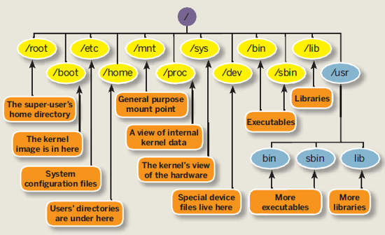
| Directory Structure
of Raspberry Pi running Soft-float Debian “wheezy” I have created an overview directory maps of my Raspberry Pi directory map to assist me in understanding the files modification that I will be dealing with. Learning how things are being organised in a Linux platform. |
/~–/bin Essential
commands that all user | |-/boot Information that boots the machine, including Kernel. | |-boot.rc | |-/dev Device driver for all the hardware peripherals. | |-/block | |-/bus | |-/char | |-/disk | |-/input | |-/mapper | |-/net | |-/pts | |-/raw | |-/snd |-/etc Configuration files for your system. | |-/alternatives | |-/apm | |-/apparmor.d | |-/apt | |-/avahi | |-/bash_completion.d | |-/ca-certificates | |-/calendar | |-/console-setup | |-/ConsoleKit | |-/cron.d | |-/cron.daily | |-/cron.hourly | |-/cron.monthly | |-/cron.weekly | |-/dbus-1 | |-/default | |-/dhcp | |-/dhcp3 | |-/dictionaries-common | |-/dillo | |-/dpkg | |-/emacs | |-/fonts | |-/fstab.d | |-/gconf | |-/gdb | |-/ghostscript | |-/groff | |-/gtk-2.0 | |-/gtk-3.0 | |-/ifplugd | |-/init | |-/init.d save and register scripts in this directory to auto run when bootup or shutdown | |-/insserv | |-/insserv.conf.d | |-/iproute2 | |-/kbd | |-/ld.so.conf.d | |-/ldap | |-/libnl-3 | |-/libpaper.d | |-/lightdm | |-/logcheck | |-/logrotate.d | |-/menu | |-/menu-methods | |-/modprobe.d | |-/network | |-/opt | |-/pam.d | |-/perl | |-/pm | |-/polkit-1 | |-/profile.d | |-/pulse | |-/python | |-/python2.7 | |-/python3 | |-/python3.2 | |-/rc0.d | |-/rc1.d | |-/rc2.d | |-/rc3.d | |-/rc4.d | |-/rc5.d | |-/rc6.d | |-/rcS.d | |-/request-key.d | |-/rsyslog.d | |-/samba | |-/security | |-/selinux | |-/sgml | |-/skel | |-/ssh | |-/ssl | |-/sudoers.d | |-/sysctl.d | |-/systemd | |-/terminfo | |-/triggerhappy | |-/udev | |-/ufw | |-/vim | |-/wpa_supplicant | |-/X11 | |-/xdg | |-/xml | |-/xpdf | |-inittab controls the startup/initialization process (example: auto login) | |-profile | |-rc.local | |-/home Home directory for each of the user | |~/pi (User named pi) | |-/Desktop | |-/python_games | |-.bashrc script trigger everytime a specific user logs in | |-/lib Library or code, Kernel or other programs use. | |-/arm-linux-gnueabi | |-/firmware | |-/init | |-/lsb | |-/modprobe.d | |-/modules | |-/systemd | |-/terminfo | |-/udev | |-/xtables | |-/lost+found | |-/media Temp media (disk, CD-ROM) | |-/mnt Temp media (disk, CD-ROM, network drive) | |-/opt Location for installing new software package. | |-/java | |-/pi4j | |-/vc | |-/proc | |-/root Super user’s home directory | |-/run | |-/ConsoleKit | |-/dbus | |-/lock | |-/mount | |-/network | |-/sendsigs.omit.d | |-/shm | |-/sshd | |-/udev | |-/sbin Commands for system adminstrator. | |-/selinux | |-/srv Data for system’s services (programs running in the background) | |-/sys | |-/block | |-/bus | |-/class | |-/dev | |-/devices | |-/firmware | |-/fs | |-/kernel | |-/module | |-/power | |-/tmp for storing temp files | |-/usr A complex hierarchy of additional programs and files | |-/bin | |-/games | |-/include | |-/lib | |-/local | |-/sbin | |-/share | |-/src | |-/var The data that changes frequently. (log files, emails) | |-/backups | |-/cache | |-/lib | |-/local | |-/log | |-/opt | |-/spool | |-/tmp |
Linux
Files and Directory Structure Reference
|
/~–/bin Essential
commands that all user | |-/boot Information that boots the machine, including Kernel. | |-/dev Device driver for all the hardware peripherals. | |-/cd-rom | |-/fd0 | |-/fd1 | |-/hda | |-/hda1 | |-/hda2 | |-/hdb | |-/hdb1 | |-/hdb2 | |-/sda | |-/sda1 | |-/etc Configuration files for your system. | |-/home Home directory for each of the user | |~/pi (User named pi) | |-/Desktop | |-/lib Library or code, Kernel or other programs use. | |-/media Temp media (disk, CD-ROM) | |-/mnt Temp media (disk, CD-ROM, network drive) | |-/opt Location for installing new software package. | |-/root Super user’s home directory | |-/sbin Commands for system adminstrator. | |-/srv Data for system’s services (programs running in the background) | |-/tmp for storing temp files | |-/usr A complex hierarchy of additional programs and files | |-/X11R6 | |-/bin | |-/games | |-/include | |-/lib | |-/local | |-/sbin | |-/share | |-/src | |-/var The data that changes frequently. (log files, emails) -/??? -> Directory related to the Linux operating system that needs careful attention in handling. |
Linux
Command Reference |
|
Add Wifi to Raspberry Pi WiFi dongle keyword |
Commands Illustration |
In order to connect to the Wifi, the first thing you will need is a Wifi dongle for your Raspberry Pi. The following contains the list of Wifi adaptors available that can work with Raspberry Pi. http://elinux.org/RPi_USB_Wi-Fi_Adapters In this example, D-Link DWA-123, H/W Ver.: B1, P/N IWA123EU…..B1G |
|
| Edit and Setup the network interface configuration | pi@raspberrypi ~ $ sudo nano /etc/network/interfaces |
Original setup look like the following, |
|
If you have a DHCP server, change to the following |
|
| If you are using a static IP, change to the following —————————————————— auto lo iface lo inet loopback iface eth0 inet dhcp allow-hotplug wlan0 iface wlan0 inet manual address 192.168.0.100 netmask 255.255.255.0 gateway 192.168.0.1 wpa-roam /etc/wpa_supplicant/wpa_supplicant.conf |
|
| Setup the WPA configuration, the following block to the file. Change the text in blue to your router settings. | pi@raspberrypi ~ $ sudo nano /etc/wpa_supplicant/wpa_supplicant.conf |
| network={ ssid=”SSID-GOES-HERE” proto=RSN key_mgmt=WPA-PSK pairwise=CCMP TKIP group=CCMP TKIP psk=”WIFI-PASSWORD-GOES-HERE” } |
|
| Reboot and unplug the ethernet cable. The Wifi should be taking over the network connection after the reboot. | pi@raspberrypi ~ $ sudo reboot |
| Reference: http://www.correderajorge.es/wifi-under-raspberry-pi-with-archlinux/ |

Reference book- Embedded Linux Primer (2nd Edition), A
Practical, Real-World Approach, by Christopher Hallinan (indepth
details of Linux OS operations) To explore list
– start up script, shutdown script
– Play Audio, Display images, Video – C I/O, UART, SPI programming
Keyword: Raspberry Pi, electronic hardware setup, UART, I2C, SPI,
Digital I/O port, Python Programming, C Programming.


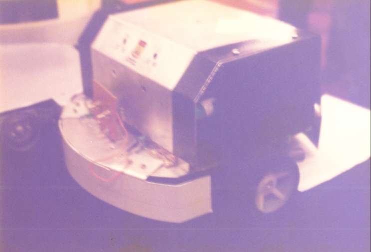


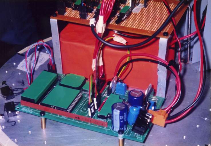
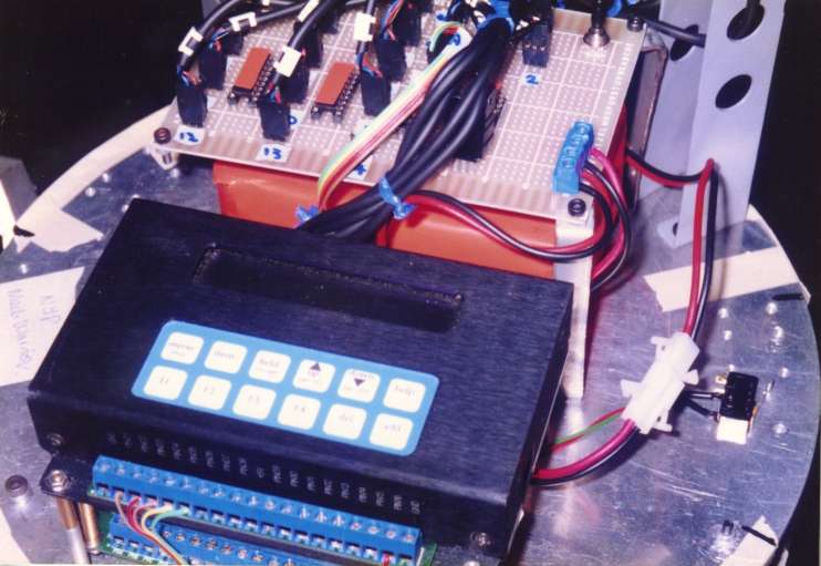

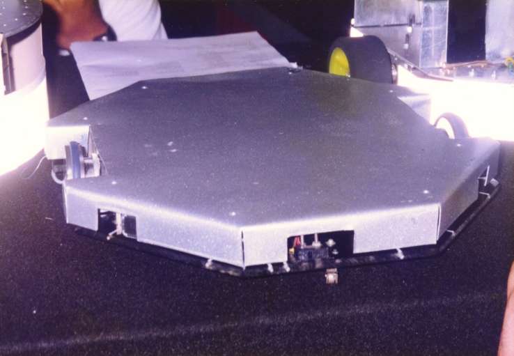

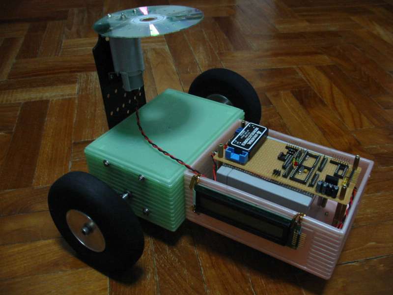
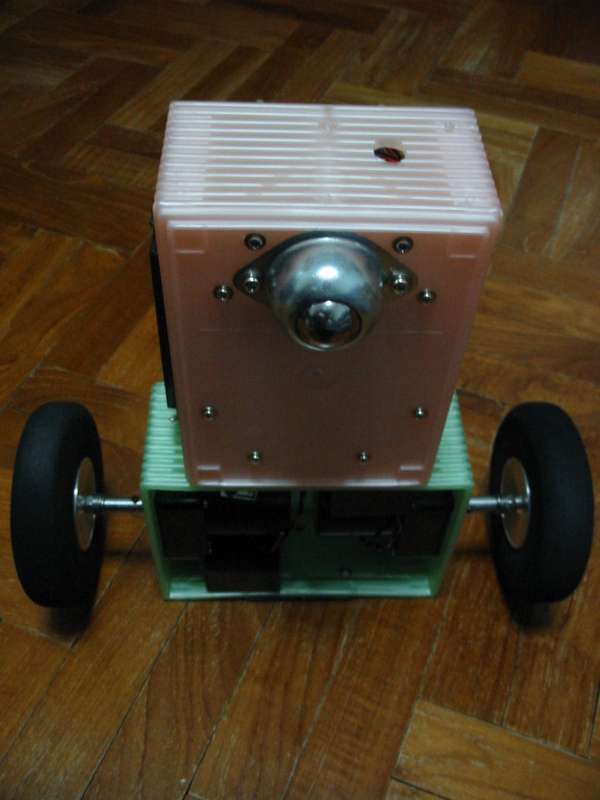
 This
is one of the robot using ultra sonic sensing. The sensor is enclose
behind the casing. We are very aware that only this type of sensor at
that time, can be mounted in this manner. We were trying very hard to
analysis all possible threat for Robot Battlefield 1998.
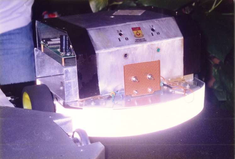
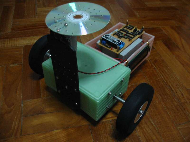
This
is one of the robot using ultra sonic sensing. The sensor is enclose
behind the casing. We are very aware that only this type of sensor at
that time, can be mounted in this manner. We were trying very hard to
analysis all possible threat for Robot Battlefield 1998.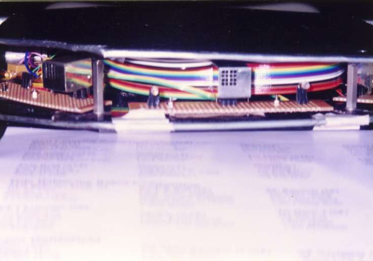


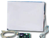
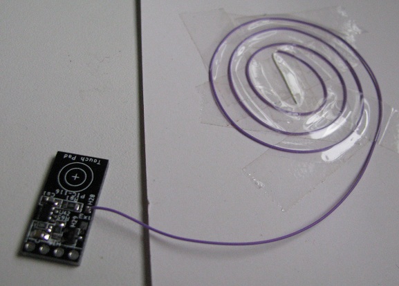
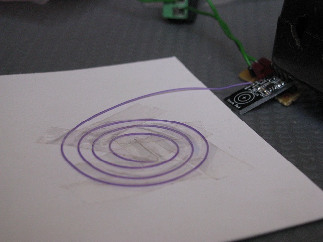
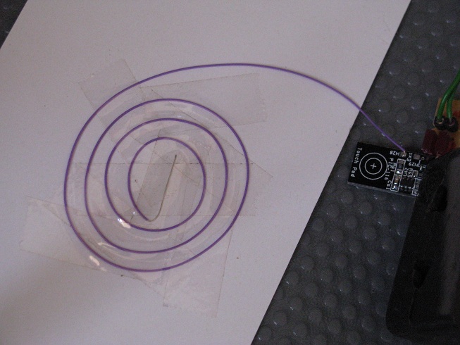
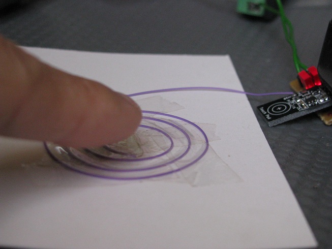
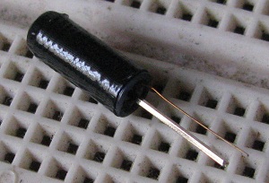
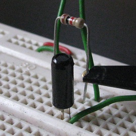
 Resistive touch sensor is
commonly deployed in our touch panel LCD monitor.
Resistive touch sensor is
commonly deployed in our touch panel LCD monitor.
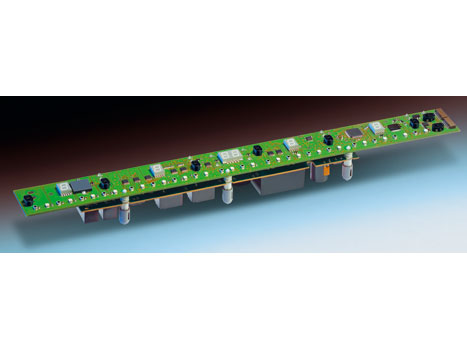
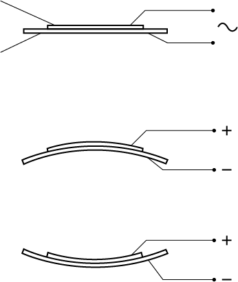
 Acroustic sound sensing, by sensitive object.


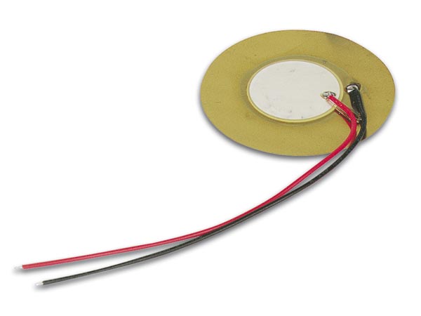


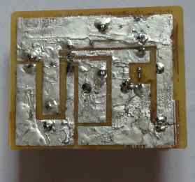
 ceramic back side of the plate.
  front side of the plate.
  side view showing the piezo, a very thin
plate.
side view showing the piezo, a very thin
plate.


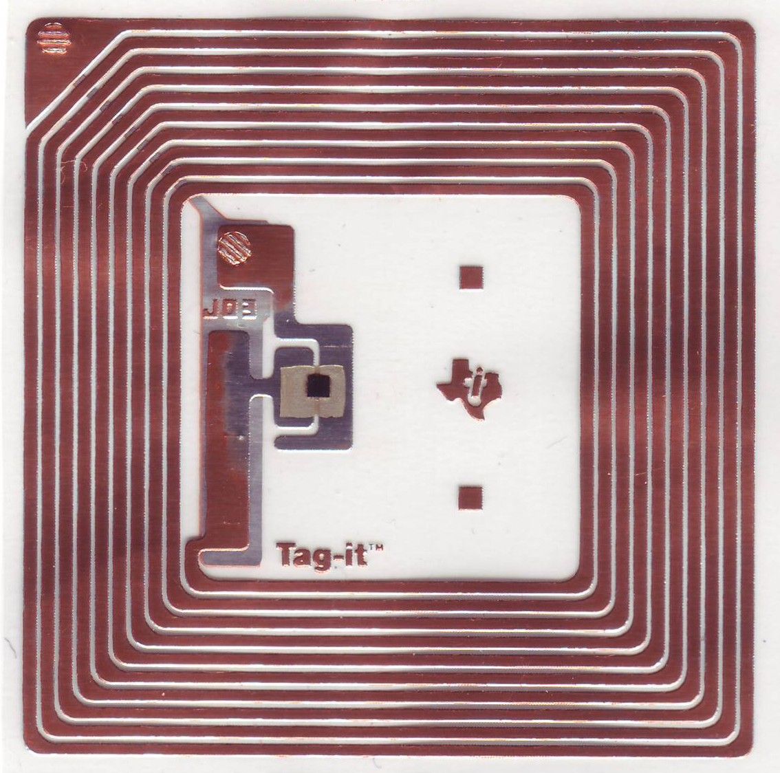


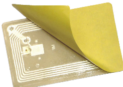
 Active RFID tag
 Active RFID tag with sensor attached


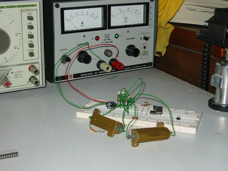
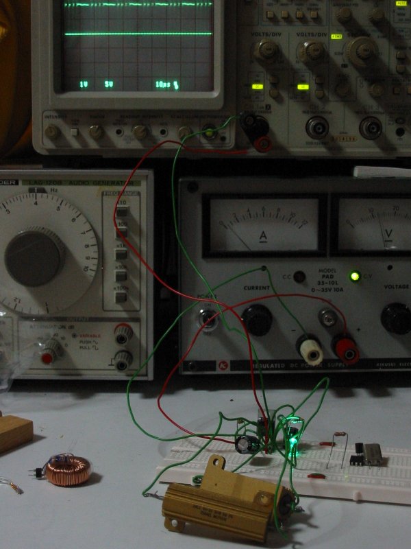
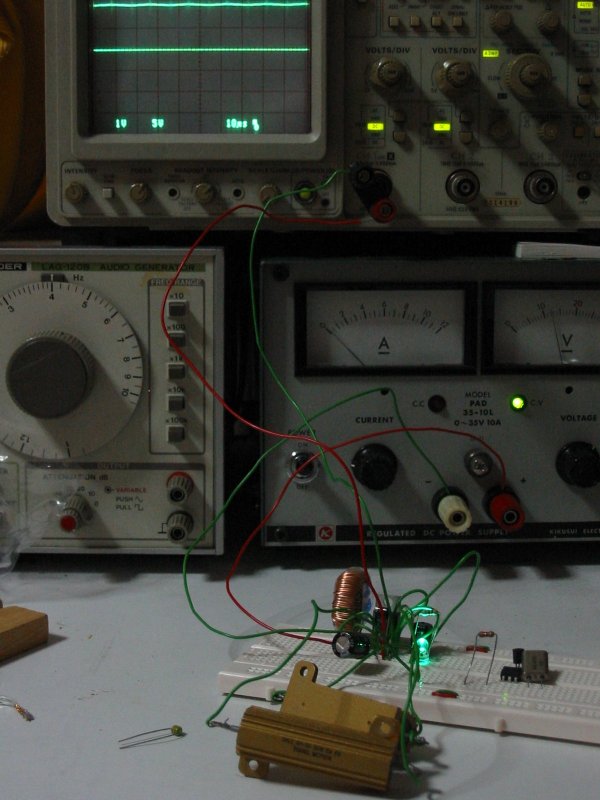
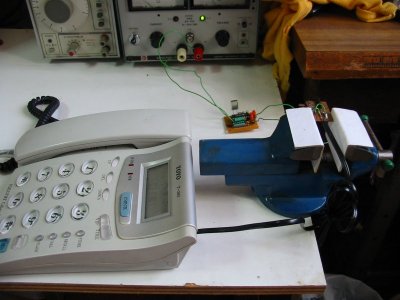
 Sample of
the 5Ω 50W aluminum house resistor used for testing 1A current
performance.
Sample of
the 5Ω 50W aluminum house resistor used for testing 1A current
performance.
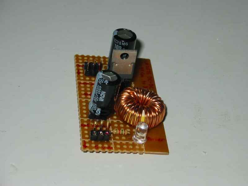
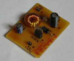
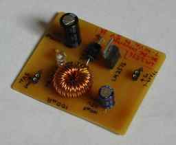
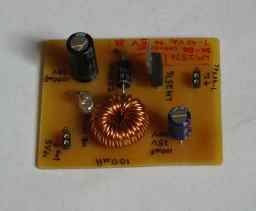
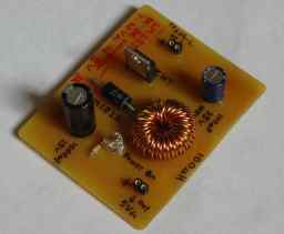
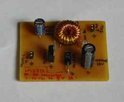

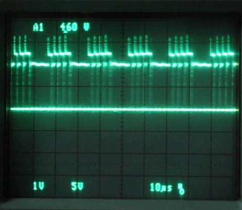

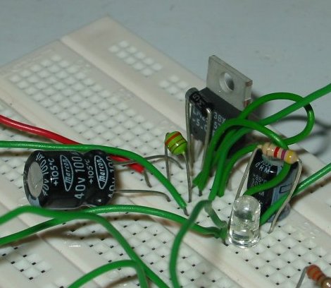
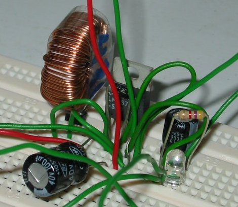


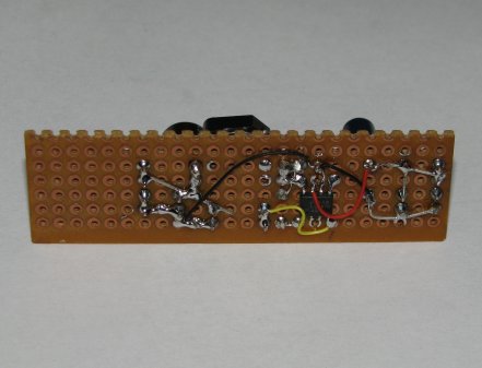

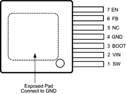


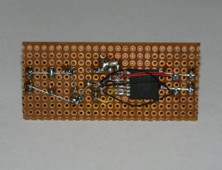

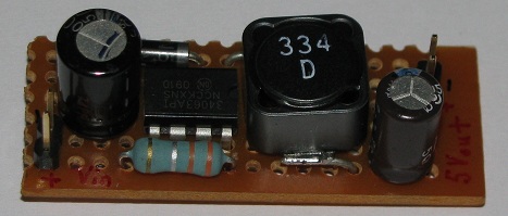
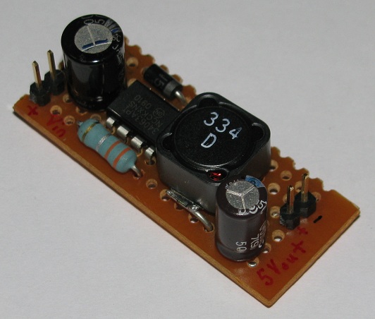


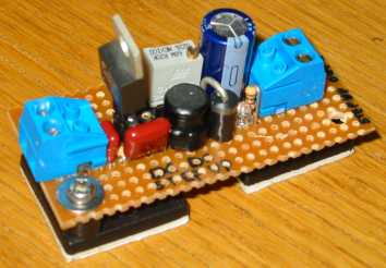


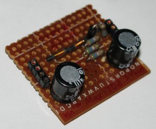
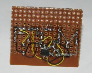


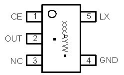
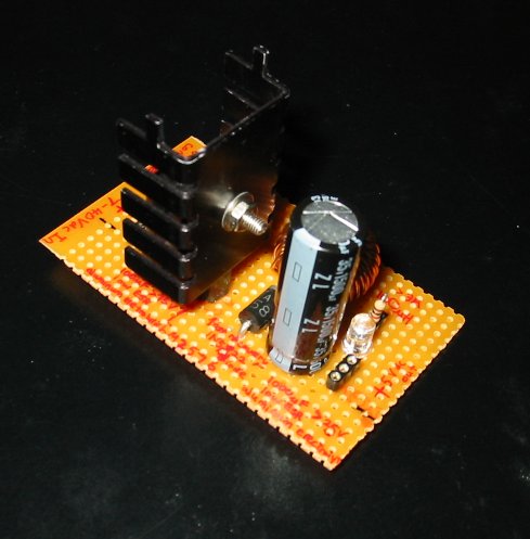
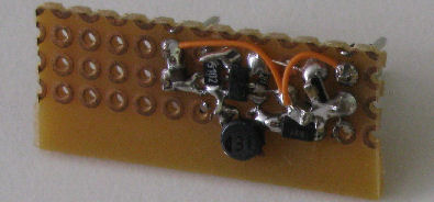
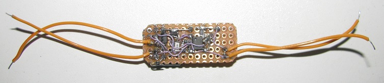
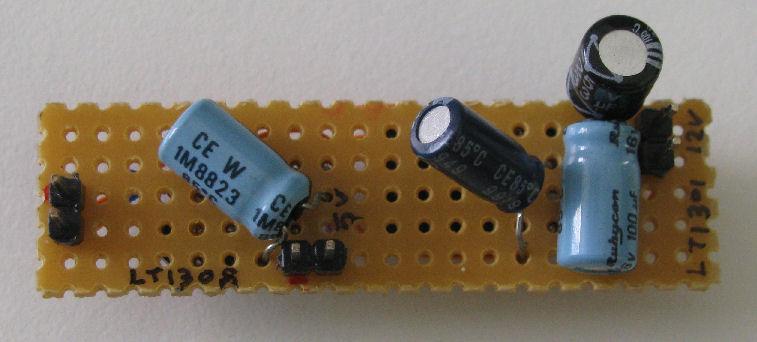
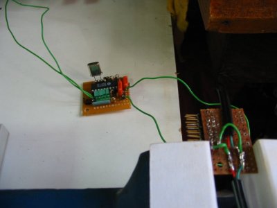
 Output 3.3V from a 1.2V alkaline battery using MCP1640
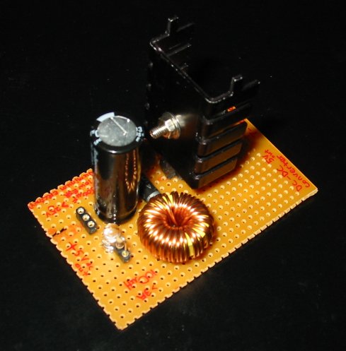
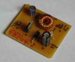
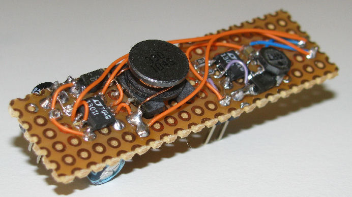
  Output 5.0V from a 3.2V LI-ION battery using MCP1640


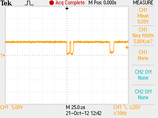
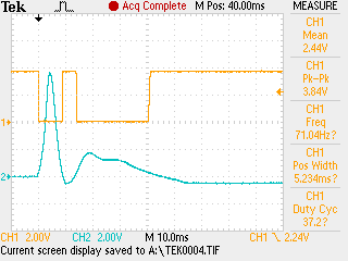
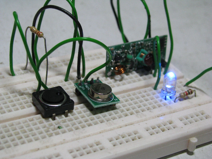
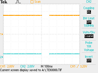
 no button
press
no button
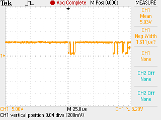
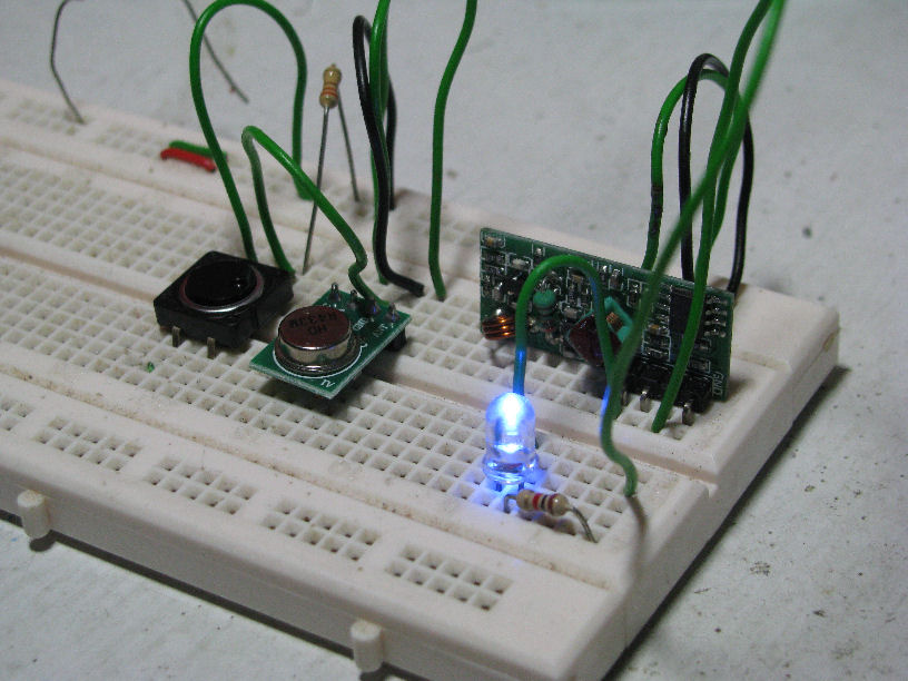
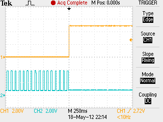
press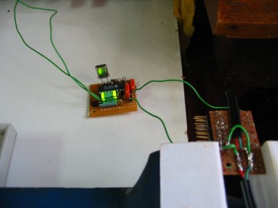 ‘1’ press
and hold
‘1’ press
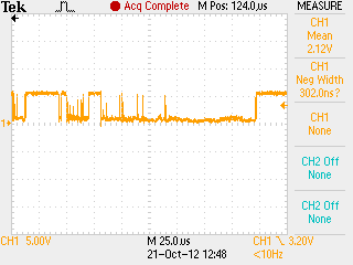
and hold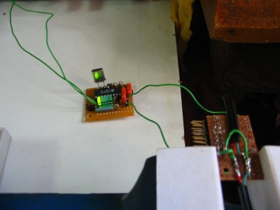 release
from button ‘1’
release
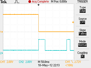
from button ‘1’ ‘2’ press
and hold
‘2’ press
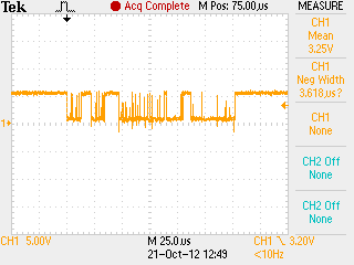
and hold release
from button ‘2’
release
from button ‘2’ ‘0’ press
and hold
‘0’ press
and hold
