Knowledge Sharing
Electronic knowledge sharing web pages.
AT Command for NB-IoT communication
Hardware used is nRF9160 modem.
Set terminal software to the following setting.
- Baudrate: 115200bps
- Data bits: 8 bits
- Stop bit: 1 bit
- Parity: None
- No hardware handshaking
Note that ↵ means sending of char 0x0D 0x0A (<CR><LF>)
//Test if modem is connected
? AT ↵
? OK ↵

//Get the modem firmware version
? AT+CGMR ↵
? 352656100032351 ↵

//Get IMEI number
? AT+CGSN ↵
? 352656100032351 ↵

//Sim Activation
? AT+CFUN=0 ↵     //turn  off cellular functionality
? OK ↵
? AT+CFUN=1 ↵     //turn  on cellular functionality
? OK ↵

//PDP Context Configuration (configure how the data packet be accepted by the telecom)
Maybe useful AT commands
AT+CGPADDR //show IP address allocated by the networkAT Command for iBasis SIM card using nRF9160 (with help from iBasis technical team)
AT+CFUN=0                           //Power of the modem every time that you change the access mode LTE-M or NB-IoT

AT%XSYSTEMMODE=1,0,1,0              //Enable LTE-M1

AT%XSYSTEMMODE=0,1,0,0              //Enable NB-IOT

AT+CGDCONT=0,"IP","ibasis.iot"      //Configure APN (Optional)

AT%XBANDLOCK=1,"10001000000000000"  //Lock the specific band for your testing, put 1 at the position of specific band (17 and 13 on this example, this is Optional)

AT+CPSMS=0                          //Disable PSM

AT+CFUN=1                           //Enable modem

AT%XSIM?                            //Enable UICC

AT+CFUN?                            //Register

AT+COPS?                            //Search network available
AT Command useful reference with other modems
AT+CSTT               //specify APN
AT-CIPPING            //ping to server to check connectivity
Reference AT command for other modems
- https://blog.wirelessmoves.com/2019/01/nb-iot-from-theory-to-practice.html
https://blog.wirelessmoves.com/2019/01/nb-iot-from-theory-to-practice-part-2.html - ublox, https://www.u-blox.com/sites/default/files/SARA-N2-Application-Development_AppNote_%28UBX-16017368%29.pdf
- NB-IoT (STARHub), https://medium.com/@ly.lee/get-started-with-nb-iot-and-quectel-modules-6e7c581e0d61
NB-IoT Smart Locks
NB-IoT locks are digital locks that can be authenticate and unlock itself wirelessly.
NB-IoT is a communication method similar to the data network that we are using for our mobile phone. So this means that the lock can be remotely control over the cellular data network.
NB-IoT has a lower cellular cost compare to LTE-M, LTE network.
List of NB-IoT digital locks (Dated: Mar 2020)
- DigitalKeys, https://www.digitalkeys.io/nb-iot-smart-padlock
- Kalewa, https://www.iotone.com/hardware/kalewa-nb-iot-smart-lock/h83047
Difference bewteen Bluetooth & NB-IoT locks
| Lock’s Communication Technology | NB-IoT | Bluetooth |
| Wireless distance | 35km | Within metres |
| Communication fee | about $1/month (10mb) | Free, unlimited |
| Communication hacking | Difficult | Easier |
| Power consumption | Higher | Lower |
| Requires cellular network to work | Can work Offline | |
| Can opens lock remotely without a smart phone | Requires a Smart Phone with bluetooth |
ARM C++ Programming Reference
Useful coding references for nRF52840 microcontrollers
Variable Declaration
Variable
signed char,   int8_t
unsigned char, uint8_t
signed short,  int16_t
unsigned short,uint16_t
signed int,    int32_t
unsigned int,  uint32_t
signed long,    int64_t
unsigned long,  uint64_t
Useful Basic Function
nrf_delay_ms(500);                 //delay in msec
bsp_board_init(BSP_INIT_LEDS);     //initialising LED
bsp_board_led_invert(0);           //toggle LED
nrf_gpio_pin_set(LED_1); or bsp_board_led_on(0);
nrf_gpio_pin_clear(LED_1); or bsp_board_led_off(0);
LED_1 = NRF_GPIO_PIN_MAP(0,13)
UART
//UART initialisation
const app_uart_comm_params_t comm_params =
      {
          RX_PIN_NUMBER,
          TX_PIN_NUMBER,
          RTS_PIN_NUMBER,
          CTS_PIN_NUMBER,
          UART_HWFC,
          false,
#if defined (UART_PRESENT)
          NRF_UART_BAUDRATE_115200
#else
          NRF_UARTE_BAUDRATE_115200
#endif
      };

APP_UART_FIFO_INIT(&comm_params,
                         UART_RX_BUF_SIZE,
                         UART_TX_BUF_SIZE,
                         uart_error_handle,
                         APP_IRQ_PRIORITY_LOWEST,
                         err_code);

    APP_ERROR_CHECK(err_code);

uint8_t cr;           //declare byte
app_uart_put(cr);     //send byte
app_uart_get(&cr);    //get byte
printf("\r\nUART example started.\r\n");     //print to UART
nRF5x Project Structure
All the function is written in a manner that is portable and general purpose coding. This may make it very difficult to read and understand. But basically, it works like PIC microcontroller where each pin or peripheral can be individually configure.
The entry point to the program is at “main.h” -> “int main(void)”.
Hardware specific “fixed” configuration are all done in “pca10056.h“. All pins input/output definition are configured in this file which is very specific to this designed pca10056 circuit board.
“boards.c” contains generic codes for managing the LED and Push Buttons codes.
Project (Solution) specific codes will be under the Application folder. Usually consist of “main.c” where the code starts, and “sdk_config.h” where are the configuration of the application will be.
Function that starts with sd_XXXXXX(), these are the basic functions provided directly from softdevice API module.
Function that starts with nrf_XXXXXX(), these are functions by nRF encapsulation softdevice API sd_XXXXXX().
Data type naming convention ends with XXXXXX_t
sec  - security
conn - connection
lbs  - led button service
ble  - Bluetooth low energy
params-parameters
auth - authorised
evt  - event
adv  - advertisement
lesc - LE security
len  - length
gattc_evt- GATT client event
gatts_evt- GATT server event
Peripheral useful for projects
More information of the examples project can be found at
https://infocenter.nordicsemi.com/index.jsp?topic=%2Fcom.nordic.infocenter.sdk5.v13.0.0%2Fexamples.html
More information about the library used in the example, refer to the SDK Library reference notes,
https://infocenter.nordicsemi.com/index.jsp?topic=%2Fstruct_sdk%2Fstruct%2Fsdk_nrf5_latest.html
- Digital IO pins (project “blinky“)
- Pin Change Interrupt (project “pin_change_int“)
- UART (project “uart“, “serial“)
- Timer (project “timer“, “gpiote“)
- Pin Change Interrupt (project “pin_change_int”)
- Power Management (project “pwr_mgmt”)
- SPI (project “spi“)
- PWM (project “led_softblink“, “low_power_pwm“)
- Watch Dog Timer (project “wdt”)
- Low Energy Bluetooth BLE
- USB BLE UART
- USB HID
Pin maps for the nRF52840-DK board examples demonstration
| Peripherals | Pin out in the nRF52840 example demo |
| LED1 | P0.13 |
| LED2 | P0.14 |
| LED3 | P0.15 |
| LED4 | P0.16 |
| SW1 | P0.11 |
| SW2 | P0.12 |
| SW3 | P0.24 |
| SW4 | P0.25 |
| UART-RX | P0.08 |
| UART-TX | P0.06 |
One of the more important BLE event function
This ble_evt_handler() is callback whenever the BLE events occurs. The lower level will be called and propagated up to our application level through ble_evt_handler() where we will handle the BLE message.
For interrupt there are a total of 4 levels. Highest interrupt priority is taken by SoftDevice, the next level is by the application. Followed by a lower priority SoftDevice, then the lowest priority to the application.
How interrupts are handled by SoftDevice.
https://infocenter.nordicsemi.com/index.jsp?topic=%2Fsds_s140%2FSDS%2Fs1xx%2Fprocessor_avail_interrupt_latency%2Fexception_mgmt_sd.html
/**@brief Function for handling BLE events.
 *
 * @param[in]   p_ble_evt   Bluetooth stack event.
 * @param[in]   p_context   Unused.
 */
static void ble_evt_handler(ble_evt_t const * p_ble_evt, void * p_context)
The path of the incoming data event (BLE_GATTS_EVT_WRITE) start from
ble_conn_params.c->ble_evt_handler(ble_evt_t const * p_ble_evt, void * p_context),
then followed by
ble-lbs.c->ble_lbs_on_ble_evt(ble_evt_t const * p_ble_evt, void * p_context)
then
main.c->ble_evt_handler(ble_evt_t const * p_ble_evt, void * p_context)
For the event object p_ble_evt, the data structure is very large. But not all data in the structure are valid. It depends on the event that had took place. Read only that section of the structure. nRF simply lump everything into this single data structure. In actual fact the data communication isn’t so large.
nRF Object Class Documentation
Application Level
---------------------------
ble_lbs_c.c
- LED Button Service modules

Middle Level
---------------------------
nrf_ble_gq.c
- GATT request queue module. Commands from application to SoftDevice are put to a queue system here

Close to SoftDevice Level
---------------------------
nrf_sdh.h

Low Level (Hardware)
---------------------------
boards.h, pca10056.h, bsp.h
- hardware board related. Board Support Package
nRF Singleton Object Instance
m_ represent singleton object.

m_ble_lbs_c
- LED Button Service object for the Central device

m_scan
- BLE scanning object

m_gatt
- GATT object

m_db_disc
- DB Discovery object

m_ble_gatt_queue
- GATT queue object
p_ represent pointer to object
//Explore Variable p_ble_evt
    //  p_ble_evt
    //      header
    //          evt_id          //type of Bluetooth events
    //          evt_len
    //      evt
    //          common_evt      //common event
    //              conn_handle
    //              params
    //                  user_mem_release
    //                  user_mem_request
    //          gap_evt         //GAP originated event
    //              conn_handle
    //              params
    //                  adv_report
    //                  adv_set_terminated
    //                  auth_key_request
    //                  auth_status                     //(ble_gap_evt_auth_status_t)
    //                      auth_status                 //< Authentication status, see @ref BLE_GAP_SEC_STATUS.
    //                      error_src                   //< Authentication status, see @ref BLE_GAP_SEC_STATUS.
    //                      bonded                      //< Procedure resulted in a bond.
    //                      lesc                        //*< Procedure resulted in a LE Secure Connection.
    //                      sm1_levels                  //< Levels supported in Security Mode 1.
    //                          lv1
    //                          lv2
    //                          lv3
    //                          lv4
    //                      sm2_levels                  //< Levels supported in Security Mode 2.
    //                          lv1
    //                          lv2
    //                          lv3
    //                          lv4
    //                      kdist_own                   //< Bitmap stating which keys were exchanged (distributed) by the local device. If bonding with LE Secure Connections, the enc bit will be always set.
    //                          enc
    //                          id
    //                          link
    //                          sign
    //                      kdist_peer                  //< Bitmap stating which keys were exchanged (distributed) by the remote device. If bonding with LE Secure Connections, the enc bit will never be set.
    //                          enc
    //                          id
    //                          link
    //                          sign
    //                  conn_param_update
    //                  conn_param_update_request
    //                  conn_sec_update
    //                  connected
    //                  data_length_update
    //                  data_length_update_request
    //                  disconnected
    //                  key_presed
    //                  lesc_dhkey_request
    //                  passkey_diplay
    //                  phy_update
    //                  phy_update_request
    //                  qos_channel_survey_report
    //                  rssi_changed
    //                  scan_req_report
    //                  sec_info_request
    //                  sec_params_request
    //                  sec_request
    //                  timeout
    //          gattc_evt       //GATT client
    //              conn_handle
    //              error_handle
    //              gatt_status
    //              params
    //                  attr_info_disc_rsp
    //                  char_disc_rsp
    //                  char_val_by_uuid_read_rsp
    //                  char_vals_read_rsp
    //                  desc_disc_rsp
    //                  exchange_mtu_rsp
    //                  hvx
    //                  prim_srvc_disc_rsp
    //                  read_rsp
    //                  rel_disc_rap
    //                  timeout
    //                  write_cmd_tx_complete
    //                  write_rsp
    //          gatts_evt       //GATT server
    //              conn_handle
    //              params
    //                  authorize_request
    //                  exchange_mtu_request
    //                  hvc
    //                  hvn_tx_complete
    //                  sys_attr_missing
    //                  timeout
    //                  write
    //          l2cap_evt       //L2CAP, Logical Link Control and Adaptation Layer Protocol
    //              conn_handle
    //              local_cid
    //              params
    //                  ch_sdu_buf_released
    //                  ch_setup
    //                  ch_setup_refused
    //                  ch_setup_request
    //                  credit
    //                  rx
    //                  tx
Naming convention used in nRF SDK BLE codes
....xxx_t => the "_t" defines the data object type.

scan_evt => scan event data to the main application

nrf_ble_scan => Bluetooth scanning parameters

ble_gap_evt_adv_report => Advertise Report object
ble_evt_t -> ble_gap_evt_t -> ble_gap_evt_adv_report_t

ble_gap_evt => GAP event

//Advertise Data
p_adv_report->data.p_data => Advertising data pointer
p_adv_report->data.len => Advertising data length
Example data:
03 19 00 00 02 01 06 0E |........
09 4E 6F 72 64 69 63 5F | Nordic_
42 6C 69 6E 6B 79       |Blinky

Advertise data starts (length of 22 of the whole packet)
This advertise packet consist of 3x Advertising Data (AD) elements

First byte 03 indicates the length of the first element which is 03 19 00 00.
19 is the AD type «Appearance»
00 00 is the data for Appearance which is unknown
The next set of AD element is 02 01 06.
First byte 02 indicates the length.
01 is the AD type for «Flags»
06 is the data for flags.
It indicates that BR/EDR is Not supported, and LE General Discoverable Mode is true.
The next set of AD element is 0E 09 4E 6F 72 64 69 63 5F 42 6C 69 6E 6B 79
0E is the total number of data bytes which is 14.
The AD type is 09, which stands for «Complete Local Name».
The data 4E 6F 72 64 69 63 5F 42 6C 69 6E 6B 79 represent "Nordic_Blinky" which is the name of the device.

The AD type code can be found on this page,
https://www.bluetooth.com/specifications/assigned-numbers/generic-access-profile/
<- Back to Bluetooth Resources Page
Nordic Bluetooth Resources Page
For beginner learning Bluetooth using Nordic microcontroller chip. Please go to this page “Guide to Nordic Bluetooth BLE for Beginner“
Possible source of formal training to Nordic nRF microcontroller programming.
https://embeddedcentric.com/nordic-ble-training/
Notes: Possible point of improving Bluetooth product.
- Company Identity. Register for an unique company ID code, and implement into Bluetooth product. Display of Nordic ID 0x0059 as the company ID can be a security breach.
https://www.bluetooth.com/specifications/assigned-numbers/company-identifiers/
https://www.bluetooth.com/develop-with-bluetooth/join/
https://www.bluetooth.com/develop-with-bluetooth/join/membership-benefits/
https://devzone.nordicsemi.com/f/nordic-q-a/7594/about-company-identifiers
https://devzone.nordicsemi.com/f/nordic-q-a/2636/using-nordic-manufacturer-id-in-advertizing-data
https://devzone.nordicsemi.com/f/nordic-q-a/24449/advertising-manufacturing-specific-data-without-company-id
- XXX Bluetooth (Technical Overview)
https://www.pic-control.com/bluetooth-technical-overview/ - Nordic Chip Programming
https://www.pic-control.com/nordic-chip-programming/ - Thingy 91 Tutorial Startup Guide
https://www.pic-control.com/thingy-91-tutorial-startup-guide/ - nRF52840-DK BLE Bluetooth Development Kit Tutorial Start-up Guide
https://www.pic-control.com/nrf52840-dk-ble-bluetooth-development-kit-tutorial-start-up-guide/ - nRF52840 Dongle (Good programming tutorial resource)
https://devzone.nordicsemi.com/nordic/short-range-guides/b/getting-started/posts/nrf52840-dongle-programming-tutorial - nRF52840 (modifying source-code from example for own custom board)
https://learn.sparkfun.com/tutorials/nrf52840-advanced-development-with-the-nrf5-sdk/all - Compare nRF52840 nRF52832, https://www.cnx-software.com/2017/08/09/nordic-semi-nrf52840-vs-nrf52832-vs-nrf52810-comparison-for-bluetooth-5-applications/
- Learning how Bluetooth connects
https://www.pic-control.com/learning-how-bluetooth-connects/ - XXX BLE Blinky Application (Server & Client)
https://www.pic-control.com/ble-blinky-application/ - Bluetooth GATT protocol
https://www.pic-control.com/bluetooth-gatt-protocol-for-bluetooth-low-energy-ble-4-0/ - Setup to Test Radio
https://www.pic-control.com/setup-to-test-radio/ - Bluetooth Sniffing using Wireshark & nRF52 DK Board
https://www.pic-control.com/bluetooth-sniffing-using-wireshark-nrf52832-dk-board/ - *** Setting up Kali Raspberry Pi for Bluetooth Hacking/Sniffing
https://null-byte.wonderhowto.com/how-to/detect-bluetooth-low-energy-devices-realtime-with-blue-hydra-0179744/
http://www.secuid0.net/?p=471
https://github.com/greatscottgadgets/ubertooth/wiki/Capturing-BLE-in-Wireshark - *** Setting up Eclipse IDE for nRF52840 development work
https://www.disk91.com/2017/technology/hardware/discover-nordic-semi-nrf52832/
https://devzone.nordicsemi.com/nordic/nordic-blog/b/blog/posts/development-with-gcc-and-eclipse - Cortex M4 C++ programming, Nordic API reference.
https://www.pic-control.com/arm-c-programming-reference/ - In depth topic on Nordic SDK: Bluetooth low energy Advertising, a beginner’s tutorial
Handling advertising data, manufacturer specific data.
https://devzone.nordicsemi.com/nordic/short-range-guides/b/bluetooth-low-energy/posts/ble-advertising-a-beginners-tutorial
Bluetooth Smart and the Nordic’s Softdevices – Part 1 GAP Advertising
https://devzone.nordicsemi.com/nordic/short-range-guides/b/bluetooth-low-energy/posts/bluetooth-smart-and-the-nordics-softdevices-part-1
Bluetooth Smart and the Nordic’s Softdevices – Part 2 Connection
https://devzone.nordicsemi.com/nordic/short-range-guides/b/bluetooth-low-energy/posts/bluetooth-smart-and-the-nordics-softdevices-part-2 - In depth topic on Nordic SDK: Bluetooth low energy central tutorial
https://devzone.nordicsemi.com/nordic/short-range-guides/b/bluetooth-low-energy/posts/ble-central-tutorial - In depth topic on Nordic SDK: Bluetooth low energy Services, a beginner’s tutorial
https://devzone.nordicsemi.com/nordic/short-range-guides/b/bluetooth-low-energy/posts/ble-services-a-beginners-tutorial - S140 SoftDevice functions
https://infocenter.nordicsemi.com/topic/com.nordic.infocenter.s140.api.v7.0.1/group___b_l_e___g_a_p___f_u_n_c_t_i_o_n_s.html - Setting up Eclipse for ARMS Cortex development work (only for development, and cannot be used for SEGGER debugging)
Nordic nRF9160 Certification
Certification resources referred by AVNET (Nordic Product Distributor)
https://www.nordicsemi.com/Products/Low-power-cellular-IoT/nRF9160-Certifications
Digital Locks Resources
- Smart Locks
https://www.pic-control.com/smart-locks/ - Bluetooth Padlock | Smart Locks for Enterprise
https://www.pic-control.com/bluetooth-padlock-smart-locks-for-enterprise/ - Compare NB-IoT with LTE-M
https://www.pic-control.com/compare-nb-iot-with-lte-m/ - NB-IoT Smart Locks
https://www.pic-control.com/nb-iot-smart-locks/ - AT command for NB-IoT communication
https://www.pic-control.com/at-command-for-nb-iot-communication/ - AT command for LTE-M communication
https://www.pic-control.com/at-command-for-lte-m-communication/
Nice Article collection
- Custom BLE Services with the nRF SDK
https://64k.space/2019/10/22/custom-ble-services-with-the-nrf-sdk/#Specifying_our_BLE_Service
Bluetooth (Technical Overview)
Bluetooth protocol operates at 2.4GHz, same as ZigBee and WiFi, working in the same unlicensed ISM frequency band.
Each network (Piconets) consist of a coordinating Master and many connecting Slaves.
Bluetooth Profile
Bluetooth profile is like the many various protocol of bluetooth communication. Some profile are for keyboards, some for storage, some for audio. Here are a list of commonly used profiles.
- Serial Port Profile (SPP), or sometimes known as UART
- Human Interface Device (HID)
- Hands-Free Profile (HFP)
- Headset Profile (HSP)
- Advanced Audio Distribution Profile (A2DP)
- A/V Remote Control Profile (AVRCP)
- Generic Attribute Profile (GATT), custom profile communication using Attribute Protocol (ATT) between the master and slave.
GATT is typically used for proprietary project that uses custom communication through the use of exchanging attribute data (Attribute Protocol, ATT).
A temperature sensor device can be acting as a server providing a service to expose the temperature reading.
A mobile smart phone is this case is a client, sending commands, requests and accepts incoming notifications/indications from the server.
The ATT attributes is made up of 4 components.
- Attribute Handle (the address of this attribute during the connection session)
2 bytes address (0x0001-0xFFFF) - Attribute Type (UUID Universally Unique Identifier)
2 or 16 bytes - Attribute Value
Variable length data. - Attribute Permissions

Bluetooth Versions
- Bluetooth v1.2
- Bluetooth v2.1 + EDR (enhanced data rate)
- Bluetooth v3.0 + HS
- Bluetooth v4.0 (BLE, Bluetooth Low Energy)
Reference:
https://learn.sparkfun.com/tutorials/bluetooth-basics/all
Reverse Engineering (Bluetooth)
Reference:
https://www.instructables.com/id/Reverse-Engineering-Smart-Bluetooth-Low-Energy-Dev/
<- Back to Bluetooth Resources Page
Nordic Chip Programming (using nRF Connect Programmer software)
Nordic Chip can be nRF52840, nRF52832, nRF9160
Methods of Programming Nordic Chips
There are 4 ways of loading your program onto Nordic chip.
- Debug header (for use of programming of the full image of the chip memory *.hex). This can be done using nRF52840-DK or nRF9160-DK board as a J-LINK programmer, or using a J-LINK programmer like the j-link Base, j-link BASE Compact or J-Link EDU Mini Programmer.
- USB Bootloader (USB Wired DFU, programming of the non-boot loader, application memory *.hex). This can be done using the onboard USB peripheral.
- Bluetooth Firmware Loader (Wireless DFU, programming of the non-boot loader, application memory *.bin). This can be done when your chip is pre-flash with bootloader firmware and SoftDevice firmware.
- USB Mass Storage (drag and drop *.hex file into the JLINK storage drive to automatically program the chip). This can be done through the nRF52840-DK or nRF9160-DK board.
Tools Required
- An nRF52840-DK kit board to act as the programmer for the chip
- nRF Connect Software
Extra programmer tool like the j-link Base, j-link BASE Compact or J-Link EDU Mini Programmer may come in handy when the tool or chip fails. Besides for nRF chip, this j-link programmer can also be used for other microcontroller chip listed on this page -> click here for supported devices J-Link.
Debug Header Method
This is the most fundamental method of loading in firmware into the Nordic nRF52840 chip.
Connect up the nRF52840-DK or nRF9160-DK kit. They are used as a programmer in this example. These boards contains a programmer chip that uses Jlink driver for connection as a programmer, to upload *.hex file into the nRF52840 or nRF9160 chips.
There is typically 3 *.hex module that you need to load into the chip’s memory. Namely,
- Bootloader
- Soft-Device
- Your Application
Different chip has its own memory map where the *.hex file should be loaded to. Here is the memory map for nRF52832, nRF52840.

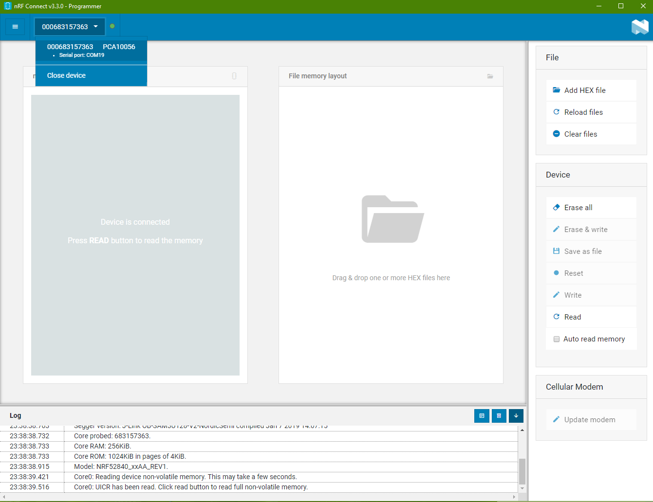
Go to the software “nRF Connect” and open the “Programmer” program.
You will come to the screenshot as follows.
Selecting Programmer Board
There is a drop-down list on the top.
When you board is connected, there should be an option in the drop down list for you to choose from. Select the programmer shown in the list.
If there is no board listed even when you got your board connected to the computer. You may also see error message in red color at the log box below. Check out the last section to see if there is a solution to resolve your problem.
Load Bootloader *.hex file
Bootloader *.hex file is the part that allows you to use USB cable to directly load the program into the chip.
It enables the chip to be able to receive it firmware through wired USB.
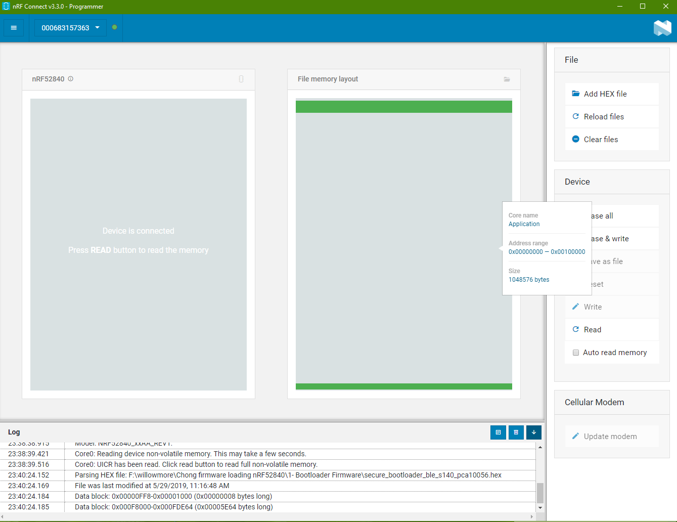
Click on the “Add HEX file” on the right side. Choose the bootloader that you want to use.
On the memory map, you will see green (bootloader sectors in use) on the top and bottom of the memory map.
Load SoftDevice *.hex file
SoftDevice is a bluetooth stack codes that you can choose to load into the chip.
There are many version to choose from. You can download them from S132 SoftDevice.
https://www.nordicsemi.com/Software-and-tools/Software/S132
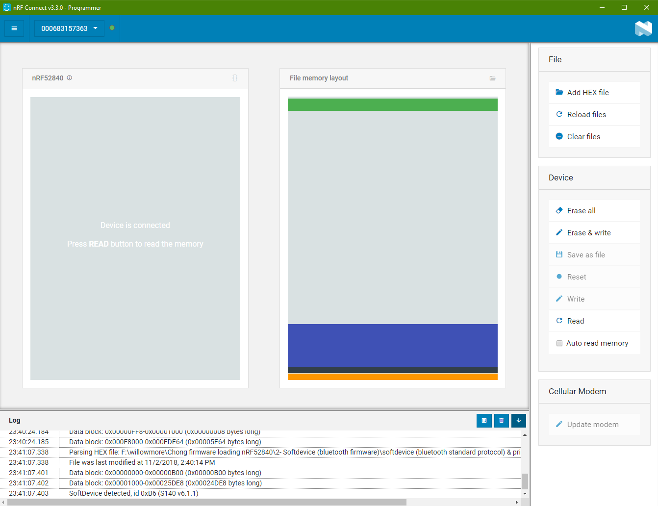
Click “Add HEX file” again to load SoftDevice *.hex file.
The SoftDevice *.hex file is loaded in the other memory of the chip. You can see from the purple color zone in the memory map shown on the right side box.
Load Application *.hex file
Lastly, this is the *.hex file for your custom application.
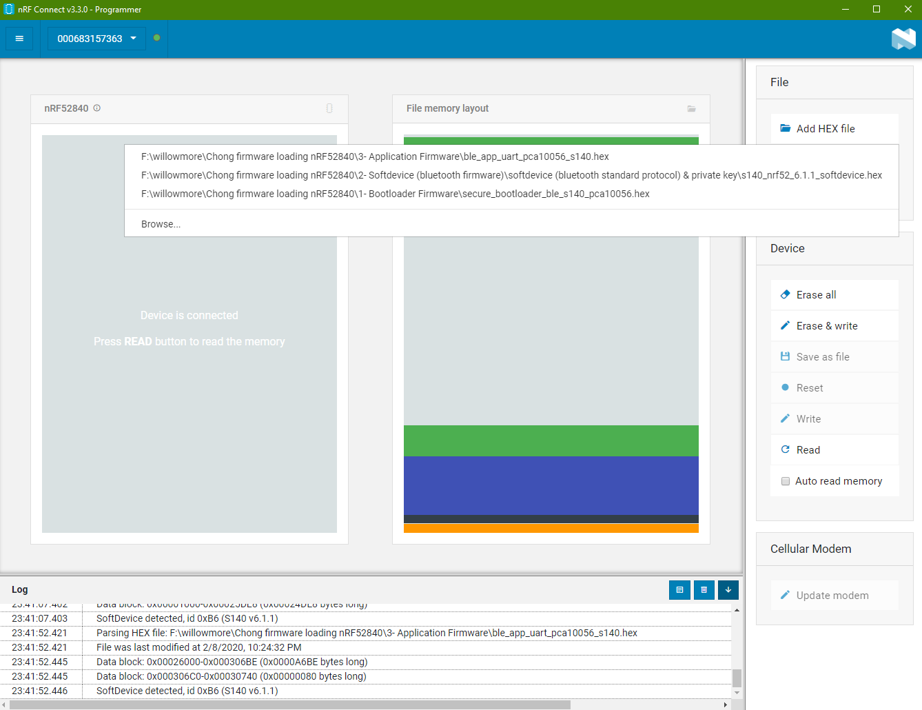
Click on “Add HEX file” again and select the *.hex file of your application.
Download Code into the Chip
Click on the button “Erase & write” to start down loading the firmware containing the 3 sector of the *.hex code into the chip at one go.
nRF52840, “Hello World” Example
Let’s use a simple project “Blinky” as our hello world example to help you kick start your chip programming experience.
Problem Encounter Case Study
Problem encounter from, nRF Connect -> Programmer
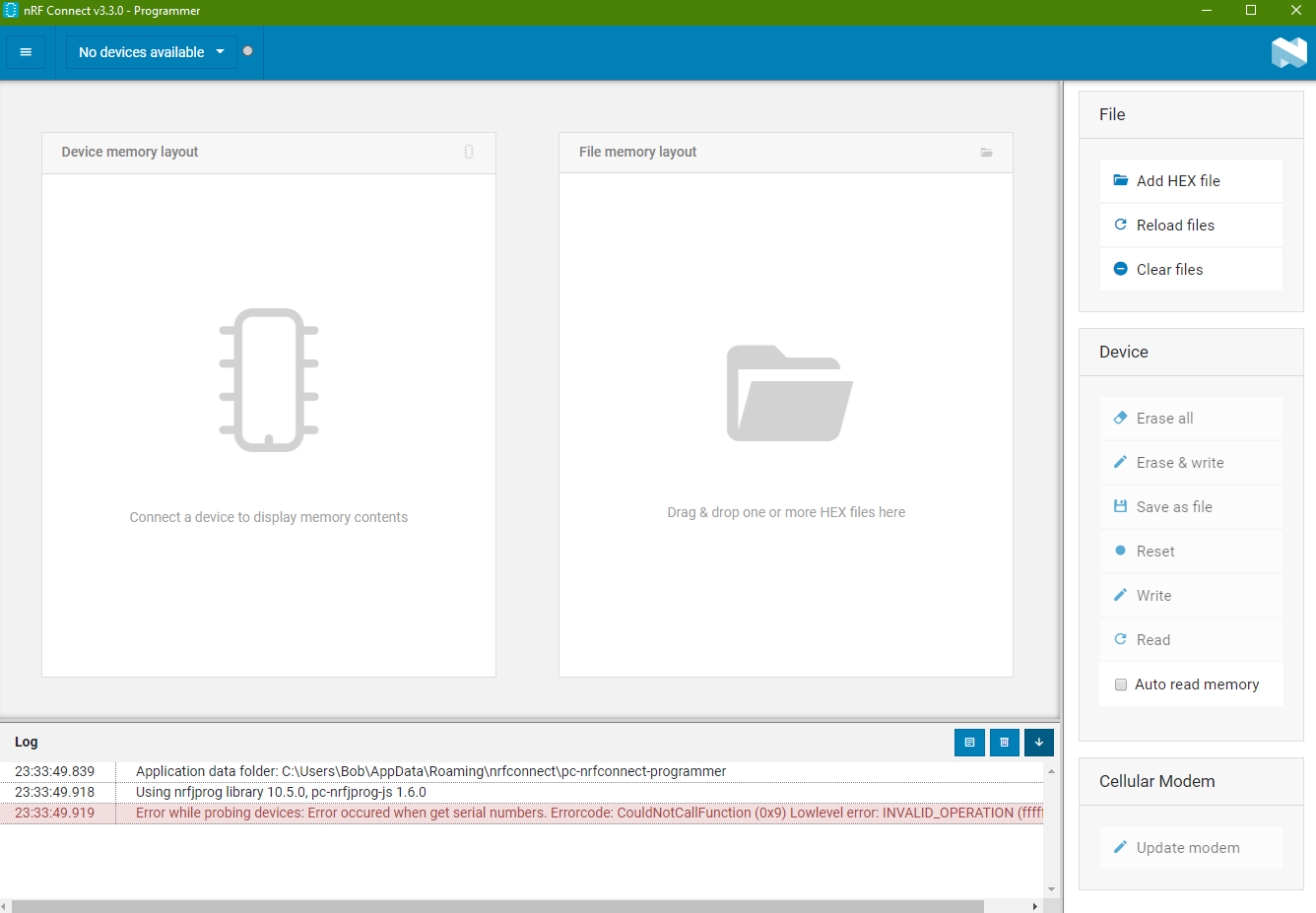
Problem “Error occured when get serial numbers”
Error encounter:
“Error while probing devices: Error occured when get serial numbers. Errorcode: CouldNotCallFunction (0x9) Lowlevel error: INVALID_OPERATION (fffffffe)numbers.“
This error occurred if JLINK driver is not installed on the system.
- Solution 1: Download the latest J-Link Software and Documentation Pack from
https://www.segger.com/downloads/jlink/#J-LinkSoftwareAndDocumentationPack
Remember to install the driver with admin rights!!! - Solution 2: Need to install nrfprog tool (nRF Command Line Tools) and this tool will install the SEGGER JLink driver. (commonly used for microcontroller chip, including chips from Microchip)
Download nRF-Command-Line Tools
https://www.nordicsemi.com/Software-and-Tools/Development-Tools/nRF-Command-Line-Tools/Download#infotabs
The problem is solved after installing the SEGGER JLink driver which comes with the nrfprog tool.
https://devzone.nordicsemi.com/f/nordic-q-a/42439/unable-to-connect-nrf52840-to-nordic-desktop-software-or-load-flash-softdevice-from-keil
https://devzone.nordicsemi.com/f/nordic-q-a/49902/error-when-launching-nrf-connect-for-desktop-on-linux - Solution 3: User Admin rights while installing the software “nRF Connect”
https://devzone.nordicsemi.com/f/nordic-q-a/49294/the-nrf-connect-application-stopped-working - Solution 4: User directory path issues
https://devzone.nordicsemi.com/f/nordic-q-a/49731/nrf-connect-v3-0-0-programmer-does-not-support-devices-nrf52832-nor-nrf9160-error-while-probing-devices-error-occured-when-get-serial-numbers-errorcode-couldnotfindjprogdll-0x2-and-the-detected-device-could-not-be-recognized-
Problem “Unsupported device. The detected device could not be recognized as neither JLink device nor Nordic USB device.”
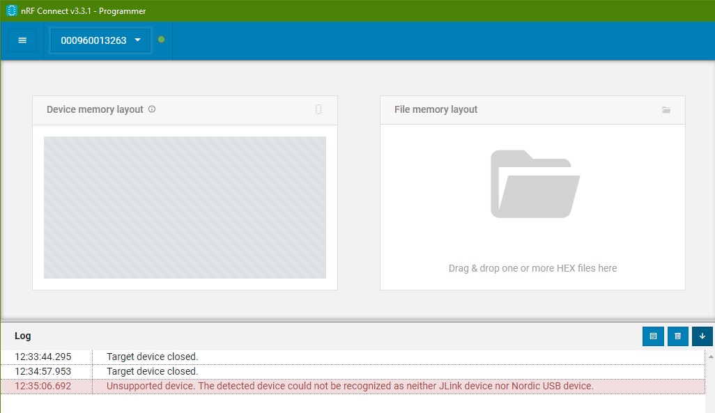
This error occurred when the JLink driver is not working.
(doesn’t work) May need to reinstall SEGGER J-Link driver. Install version 6.22g. Download the J-Link Software and Documentation Pack from
https://www.segger.com/downloads/jlink/#J-LinkSoftwareAndDocumentationPack
Solution 2, can consider reinstalling “nrfprog tool” as the previous example.
Problem: The nRF Programmer got hang when connecting to the nRF9160 chip. Log message halt at “Using nrfjprog to communicate with target”
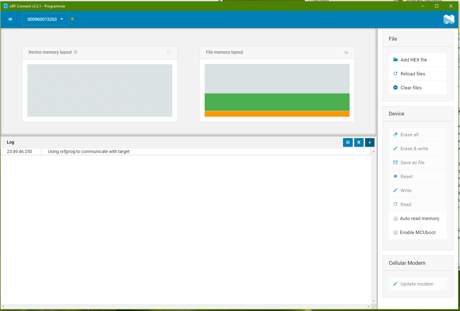
Somehow during one of the attempt to program the nRF9160 chip on Thingy91, the programmer halt.
Upon retry to connect with the chip, the log always stops at “Using nrfjprog to communicate with target”.
It doesn’t happens to the nRF52840 chip on the Thingy91. Only the nRF9160 chip is affect.
I thought it was a hardware issue. Alan from Avnet managed to recover this hang sequence by using the following command (program via command prompt)
> nrfjprog -f UNKNOWN --eraseallOnce this command is issue, the block is clear and the chip can be program normally.
<- Back to Bluetooth Resources Page
nRF52840-DK BLE Bluetooth Development Kit Tutorial Start-up Guide
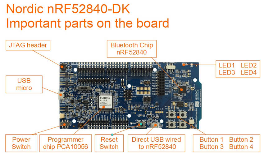
nRF52840-DK is a development kit for nRF52840 SoC (System on Chip) chip. Mainly design for Bluetooth application, supporting Bluetooth 5.0, Bluetooth Low Energy (BLE, Bluetooth 4.0).
Check out this video introduction of this nRF52840-DK development kit board.
Preparation
What do you need?
- Download Apps “nRF Toolbox for BLE” for Andriod or IOS
Demonstrate Bluetooth profile, and support Nordic UART and DFU - Download Apps “nRF Connect” for Andriod or IOS
For scanning and exploring Bluetooth Low Energy devices and communicate with them.
Support DFU and Eddystone. - Download Apps “nRF BLE Joiner” for Andriod or IOS
Proprietary method to convert Bluetooth into network devices (IPv6 nodes). - Download demo firmware from the Nordic website.
https://www.nordicsemi.com/Software-and-tools/Development-Kits/nRF52840-DK/Download#infotabs
In this example, we download the “Proximity demo“
Unzip “proximity_demo.zip”
get ready the hex file “ble_app_proximity_s132_pca10040.hex”
Inside the zip file contains readme.txt file to explain how this demo works - XXX -> Download Apps “nRF UART 2.0” for Andriod or IOS
Ways to program Nordic nRF52840 chip on the nRF52840-DK
Reference: https://devzone.nordicsemi.com/nordic/short-range-guides/b/getting-started/posts/nrf52840-dongle-programming-tutorial
https://devzone.nordicsemi.com/f/nordic-q-a/37219/how-to-upload-the-application-hex-file-uisng-usb-drag-n-drop-on-nrf52840
- Programming the nRF52840 chip, through the USB Mass Storage, vs SWD (Left side of the board)
- Programming the nRF52840 chip, through the nRF USB, vs serial USB bootloader (Bottom side of the board)
First Thing First
Download the latest SDK project files from nRF5 SDK product website. .
https://www.nordicsemi.com/eng/Products/Bluetooth-low-energy/nRF5-SDK#Downloads
The nRF5 SDK zip files contains many example projects for your to try and test.
Here is a pre-downloaded copy of nRF5 SDK ver 16.0.0 (nRF5SDK160098a08e2.zip, file size about 153MB)
in case you are having issue downloading from the official website.
Method 1 to program nRF52840 development kit via USB Storage Drive
To help you get start, to be in control of the nRF52840-DK board, I have this simple guide here to help you load in the hex file onto your nRF52840-DK board, to build up your confident.
Hex file the machine codes for the nRF52840 microcontroller chip after compiled from the source code. Nordic SDK contains both the project source code as well as the compiled *.hex file.
Here is a simplest way to test if the hex file is successfully loaded (or programmed) into the nRF52840-DK development kit.
1) Download the following files,
These 2 *.hex files are LED demonstration example which is found in the nRF5 SDK zip file that you downloaded eariler. Under the directory “examples\peripheral\blinky\hex\” & “examples\peripheral\led_softblink\hex\”. The source code can also be found in the project directory.
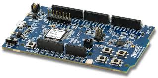
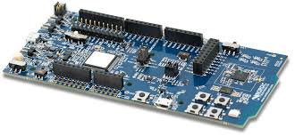
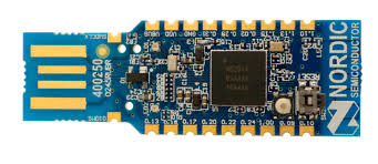
Please take note that there are project folder for different type of development board. One is for pca10040 development kit board, and the other is pca10056 development kit board. The one I have is PCA10056. You can take a look at the white sticker which is paste on top of your nRF52840-DK board to confirm which board you have. If you choose the wrong *.hex file, the example will not work. The files has a prefixed name “_pca10056.hex” at the back.
List of board types
2) Connect up your nRF52840 board with a micro USB cable.
You should be able to see a storage drive popping out from your computer. Inside this drive “JLINK”, you will see the following files inside.
- MBED.HTM
- README.TXT
- Segger.html
- User Guide.html
3) Copy the “blinky_pca10056.hex” hex file into the root of the JLINK drive.
This copy action will trigger a programming process of the hex file into the nRF52840 chip.
After a short second, you should see the LED1 LED2 LED3 LED4 on the nRF52840 board started to lights on in sequence, followed by lights off in sequence.
4) Next, copy the “led_softblink_pca10056.hex” hex file into the root of the JLINK drive.
After a second, you should see that the 4 LED now behaves differently. They will now fade out and fade on the lights. The old hex file can be remains in the drive. The programming action will only take place during the first time transferring of the *.hex file onto the JLINK drive.
That’s all for a simple demonstration of programming the nRF52840 chip that is on the nRF52840-DK development kit board. Simple just load in the hex file to nRF52840-DK board.
You have successfully programmed the nRF52840 chip.
Method 2 to program nRF52840 development kit via SEGGER Embedded Studio Software
1) Install and open the SEGGER Embedded Studio. If you are facing issue with the installation, you may like to visit this page for some SEGGER installation experience.
2) Open source code projects. We will use the project “blinky_pca10056”
From the menu bar go to File -> Open Solution
Open solution is like open project in other development platform. Go to the nRF5 SDK directory and select the project file “examples\peripheral\blinky\pca10056\blank\ses\blinky_pca10056.emProject“.
Folder “ses\” for the project files using SEGGER Embedded Studio.
Folder “armgcc\” is for the project files using GNU Arm Embedded Toolchain.
The project will be loaded.
In this project, you will see the file “main.c” where the blinky action codes is. Play around by modifying the code. This “main.c” file is share by other projects (defined by different board)
3) Program your new code to the nRF52840-DK board.
Ensure that you board is connect via the USB micro.
From the menu bar go to Build -> Build and Run (Ctrl+T or Ctrl+F5)
The SEGGER software will compile your code and load it to the nRF52840-DK board. It will take quite a couple of seconds to complete the up loading.
This completes your experience loading your codes using SEGGER Embedded Studio.
Play around with the other projects to get yourself familiar with the other peripherals on the chip nRF52840. Learning digital I/O pins and UART pins are the most important to help you get started in your microcontroller firmware programming. Once these two peripheral are mastered, understanding the rest will be much simpler.
For C++ coding reference, please click here to refer to this reference page.
Method 3 to program nRF52840 development kit via nRF Connect Programmer software
Check out this page.
https://www.pic-control.com/nordic-chip-programming/
Method 4 using nRF52840-DK as a programmer to program other boards
The nRF52840-DK can be used as a programmer to program other external board using the P19 Debug Header or the P20 Header Pins on the board. The DK board will detect the VTG pins for any board connected to it. If there is a connecting board, the nRF52840-DK will program the external board instead of the nRF52840 chip onboard the nRF52840-DK board.
The pins required for the programming are,
| Programmer Pins (Serial Wire Debug pins) | nRF52840 | nRF52832 | nRF51822 |
| VTG (input to detect voltage), (short to Vdd) | |||
| SWD IO | AC24 | Pin 26 | Pin 23 |
| SWD CLK | AA24 | Pin 25 | Pin 24 |
| Gnd Detect (detect ground) |
You can use ST-Link programmer to program the nRF52840 chip directly.
https://www.youtube.com/watch?v=_-d2d6Vc3lg
nRF52840-DK can act as a programmer. This programmer is J-Link compatible and can work with SEGGER software tool.
ST-Link and J-Link is not the same, but both can be use to program the chip nRF52840
Method 5 programming using a JLink Programmer
The method of programming using a Jlink Programmer is similar to the previous example of programming using nRF52840-DK as a programmer. Programming is done via the debugging header.
You can use the following JLink programmer.
- J-LINK EDU MINI (low cost)
- SEGGER J-Link EDU
- SEGGER J-Link PLUS (expensive)
Method 6 programming using the nRF Command Line Tools (nrfjprog)
Download and install nRF Command Line Tools “nrfjprog“. This program help loads the compiled firmware (*.hex) into the chip. This nRF Command Line Tools can be downloaded from Nordic website and install onto your computer.
Two things to take note before using this nrfjprog.
- Setup environment for nrfjprog.
- Ensure that the SDK points to the correct nrfjprog directory (version).
Add path to the environment variable of Win10, so that the program “nrfjprog.exe” can be accessible from any file directory. It is found in the following directory after installation.
C:\Program Files (x86)\Nordic Semiconductor\nrf-command-line-tools\bin
Ensure that the text file “Makefile.posix” in the SDK directory
F:\…..\nRF5 SDK\components\toolchain\gcc
is configured to point to the correct compiler’s install directory and version.
Begin
I am using the nRF52840-DK board (PCA10056), so we go to the following blinky project folder.
“…\nRF5 SDK\examples\peripheral\blinky\pca10056\blank\armgcc”
Inside the folder, it contains a “Makefile”. The make file contains the excuting of the program nrfjprog in sequence to load the compiled source code “*.hex” into the chip.
To flash the chip: (load *.hex into the chip)
//to program the nRF52 microcontroller chip with the hex file.
nrfjprog --family nrf52 --program $(OUTPUT_DIRECTORY)/nrf52840_xxaa.hex --sectorerase

//--> Please note that the microcontroller needs to be reset in order for the new firmware to run !!!
//Learning Notes:
//   flag --sectorerase     //to erase the memory sector (before the programming) where the code is flash onto.
//   flag --sectoranduicrerase     //to erase the memory sector (before the programming) where the code is flash onto.
//   flag --chiperase       //to erase all the user memory (before the programming) including UICR.
//reference: https://infocenter.nordicsemi.com/index.jsp?topic=%2Fug_nrf5x_cltools%2FUG%2Fcltools%2Fnrf5x_nrfjprogexe_reference.html

//verify the loaded firmware
nrfjprog --family NRF52 --verify nrf52840_xxaa.hex

//to reset the microcontroller chip after the programming
nrfjprog --family nrf52 --reset


//Example of programming a blinky firmware (LED indicator blinking firmware example)
> nrfjprog -f nrf52 --program blinky_pca10056.hex --sectorerase
Parsing hex file.
Erasing page at address 0x0.
Applying system reset.
Checking that the area to write is not protected.
Programming device.

//Example of verifying the firmware code flash in
> nrfjprog --family NRF52 --verify blinky_pca10056.hex
Parsing hex file.
Verifying programming.
Verified OK.

>>Example of flashing and verifying at one go
> nrfjprog --family nrf52 --program blinky_pca10056.hex --sectorerase --verify
Parsing hex file.
Erasing page at address 0x0.
Applying system reset.
Checking that the area to write is not protected.
Programming device.
Verifying programming.
Verified OK.

>>Example of flashing and verifying at one go, including a reset at the end.
> nrfjprog --family nrf52 --program blinky_pca10056.hex --sectorerase --verify --reset
To erase the chip:
nrfjprog -f nrf52 --eraseallTo execute this command is chip is hang.:
nrfjprog -f UNKNOWN --eraseallTip#: Using Win10 file explorer, you can simply key in “cmd” in the directory text field, the command prompt will be loaded with the path at the current window’s directory that you are at. Very convenient feature.
Nice video talking about make & cmake.
https://www.youtube.com/watch?v=fOtPq0PkqlE&feature=youtu.be
SDK configuration header file
In every project (solution), in the “Application” folder contains a file named “sdk_config.h” to allow you to configure some of the parameter of the project. To allow you to enable/disable software module in the project.
You can actually use a tool “CMSIS Configuration Wizard” in the SEGGER Embedded Studio to assist you in setting up an apps to assist you to do the configuration with ease.
https://infocenter.nordicsemi.com/index.jsp?topic=%2Fcom.nordic.infocenter.sdk5.v14.1.0%2Fsdk_config.html
First you have to go to File->Open Studio Folder…->External Tools Configuration.
You will need to paste some XML codes to enable the CMSIS tool.
Save the XML file. Close the SEGGER IDE and restart again.
This time round, go to the project application folder to look for the “sdk_config.h” file.
Right click it, you will now get to see there is a newly added option “CMSIS Configuration Wizard“
You can now use this to enable/disable your project configuration instead of editing on the precompiler code on the file “sdk_config.h”. Click on “save” after the changes. When a warning window pops up for file modified externally, click yes to have the changes updated onto the file.
What is
- DFU bootloader (Device Firmware Update)
<- Back to Bluetooth Resources Page
Thingy 91 Tutorial Startup Guide
When I was first handled with the task of building a Bluetooth and NB-IoT gateway, I was a bit overwhelmed by the messy and complex documentation on the manufacturer’s website. So I decide to do a write guide to start off a hello world example as I learn discover that Thingy 91 module is all about.
Start up hardware
Thingy 91 (from Nordic)
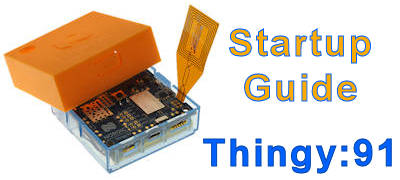
Thingy 91 is a prototyping kit which consist of the IC chip nRF9160 (for NB-IoT communication), and nRF52840 (Bluetooth Low Energy BLE 4.0, 5.0 communication). Simple battery powered electronic hardware to get engineer start up with working on nRF9160.
nRF9160-DK (from Nordic)
nRF9160-DK is similar to Thingy91, an development kit for learning nRF9160 IC chip. That why the it is named “-DK”. It consist of the same IC chip nRF9160 and nRF52840.

Check out this video introduction of nRF9160-DK development kit board.
and a quick introduction to nRF Connect SDK.
An additional big chip is found on this kit. This chip is there for the programming of the IC nRF9160 or nRF52840. A switch SW5 near this big chip is used for selecting the chip that you want to program. You can select nRF52 (for nRF52840 chip) or nRF91 (for nRF9160 chip).
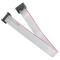
(1.27mm pitch)
Beside able to program the IC chip on its own board, this development kit can also act as a programmer to program nRF52xxx or nRF91xxx chips on other boards. You can use nRF9160 as a programmer device to program the chips (nRF52840 or nRF9160) on the Thingy91 board via the JTAG cable (10pins ribbon cable).
How to get started?
This was one big question on my head. I done many installations until I also don’t know what I was doing. Here I want to start off by learning how to program a “Hello World” firmware into nRF52840 chip first.
I decided not to rush into things and do things step by step from the basis fundamental first.
What do you need?
- Development Kit nRF9160-DK
- USB micro cable
- A computer with a Windows Operating System
Ways to program Nordic nRF52840 chip
There are a number of ways to program the Nordic chip nRF52840.
- Debug header
- USB Bootloader (Wired)
- USB Mass Storage
- Bluetooth Firmware Loader (Wireless)
Getting start with nRF9160-DK
You can refer to the reference from this webpage.
https://devzone.nordicsemi.com/nordic/cellular-iot-guides/b/getting-started-cellular/posts/getting-started-with-nrf9160-dk
Summary
- Install the software nRF Connect on your desktop computer.
- Open up this software nRF Connect.
- Go to Getting Started Assistant, click <Install>
- Open and execute the program Getting Started Assistant to guide you with the steps to take.
Summary from Getting Started Assistant
- Install the toolchain
- Clone the nRF Connect SDK
- Download SEGGER Embedded Studio
- Set up a project in SEGGER Embedded Studio
Install the toolchain
The whole installation experience is a pain. Please ensure there is no space in the name of your folders. It will not be recognized by the software tools.
- Install toolchain Chocolatey. Chocolatey tool makes software installation on WinOS looks easy. It will be like typically how we do software installation on Linux OS system. Helps you to automate and create software deployment package for Windows. Learn about Chocolatey here.
The subsequent steps, we will be doing installation and configuring of Chocolatey from WinOS command prompt. - Open a command prompt as an Administrator on your WinOS computer. Press on your keyboard Windows+X. Click on the pop-up menu “Command Prompt (Admin)” or “Windows PowerShell (Admin)”. A command prompt should pops up.
- Paste the following command text into the PowerShell,
> Set-ExecutionPolicy Bypass -Scope Process -Force; [System.Net.ServicePointManager]::SecurityProtocol = [System.Net.ServicePointManager]::SecurityProtocol -bor 3072; iex ((New-Object System.Net.WebClient).DownloadString(‘https://chocolatey.org/install.ps1’))
This will download and install Chocalatey onto your computer system. - Enter the following command text into the PowerShell to check if Chocolatey is installed.
> choco
You should receive the following message when Chocolatey is properly installed.
Chocolatey v0.10.15
Please run ‘choco -?’ or ‘choco -?’ for help menu. - Enter the following command texts, and click verify button on Getting Started Assistant. The Assistant should highlight green which indicates that the task is done properly. Do the same for the subsequent command.
> choco feature enable -n allowGlobalConfirmation - Enter the following command texts, and click on verify button.
> choco install -y cmake –installargs ‘ADD_CMAKE_TO_PATH=System’ - > choco install git
- > choco install python
- > choco install ninja
- > choco install dtc-msys2
- > choco install gperf
- Download and install ONLY the recommended version of GNU ARM Embedded toolchain so that able to cross-compile for ARM microcontroller chips. Follow what nRF Connect assistant tells you to download.
https://developer.arm.com/-/media/Files/downloads/gnu-rm/8-2019q3/RC1.1/gcc-arm-none-eabi-8-2019-q3-update-win32-sha2.exe
which is version8-2019-q3-updateof the GNU ARM Embedded toolchain.
Install the software to the root directory c:
The installed folder is probably c:\8 2019-q9-update
Change the folder name to c:\gnuarmemb
Ensure that there is a bin folder under c:\gnuarmemb\bin.
Use the Verify button to confirmed that you have done it correctly.
Please ignore the following test…..
Open up “Command Prompt” and key in the following command to check if GNU toolchain is installed.
> arm-none-eabi-gcc –version
Please ignore the following test…..
Install onto “C:\gnuarmemb” directory. (recommended by nRF Connect)
example: “C:\gnuarmemb\GNU Tools Arm Embedded\9 2019-q4-major“
Click verify on your Assistant when this is done.
Clone the nRF Connect SDK from Nordic Repository.
Nordic has developed SDK specially for their nRF chip products (only for nRF9160 or nRF5340). These source code are in Nordic repository. The following commands are to copy/update that source code onto our own local computer system.
Enter the following command texts in Windows PowerShell, and click on Verify button.
- Install West (Zephyr’s meta-tool), a swiss-army knife command-line tool .
Use pip3 to install west.
> pip3 install west - Create your own directory to store nRF Connect SDK, and create a directory (no spaces in the directory name) ncs under it.
example: e:\nRFConnectSDK\ncs\,
> cd ‘e:\nRFConnectSDK’
> mkdir ncs
> cd ncs - Initialise West meta-tool, and update it
> west init -m https://github.com/NordicPlayground/fw-nrfconnect-nrf
> west update - Visit the webpage nRF Connect SDK Release Notes to look for the version that you want to clone onto your computer system. Look for the Release Tag to use. In this example, I am looking at “nRF Connect SDK v1.2.0 Release Notes”. The Release Tag that I see from this release is “v1.2.0“. Use this tag for git checkout as shown below. This will fetch the release version v1.2.0 from the repository.
> cd ‘e:\nRF Connect SDK\ncs\nrf’
> git checkout v1.2.0
> west update
If you want the latest version (may not be a stable version from Nordic), use the command “git fetch origin” instead of “git checkout v1.2.0”. The command “west update” simply update the files to that version. - Install a list of required Python modules.
> cd ‘f:\nRF Connect SDK\ncs’
> pip3 install -r zephyr\scripts\requirements.txt
> pip3 install -r nrf\scripts\requirements.txt
> pip3 install -r bootloader\mcuboot\scripts\requirements.txt
Download SEGGER Embedded Studio
Download and install SEGGER Embedded Studio.
Set up a project in SEGGER Embedded Studio
Execute the SEGGER Embedded Studio software.
- Use command prompt to navigate to the folder where SEGGER Embedded Studio is located. In this example, it is located at “e:\nRF Connect SDK\arm_segger_embedded_studio_v442a_win_x64_nordic\bin\”
- Execute the file emStudio.exe to launch the software.
- A pop up screen may appeared indicating “No commercial-use license detected”. Activate your free license.
Setup the path of the Zephyr Base (the location of your cloned Zephyr repository, path ncs/zephyr), and the path where GNU ARM Embedded Toolchain is installed.
In the software go to Tools > Options, and select the nRF Connect tab.
In our example, the path for
- Zephyr Base, “e:\nRFConnectSDK\ncs\zephyr“
- GNU ARM Embedded Toolchain, “c:\gnuarmemb“
You can now start opening your nRF Connect project. Select File > Open nRF Connect SDK Project.
Follow the setting of the screenshot on the right.
For the board name, remember to select the name ending with xxxxxxns. Which means Non-Secure version.
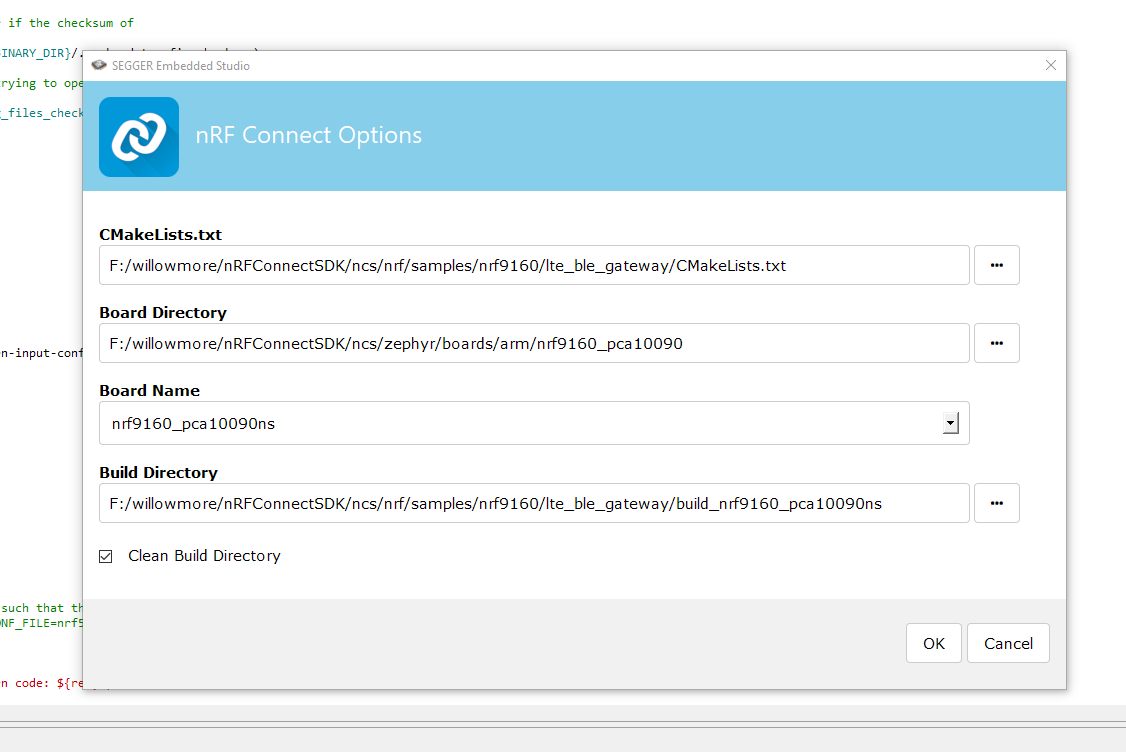
- CMakeLists.txt (location of the project makelist. Typically located at ../ncs/nrf/samples/nrf9160/lte_ble_gateway/CMakeLists.txt)
- Board Directory (location of the board used for the project. Typically located at ../ncs/zephyr/boards/arm/nrf9160_pca10090 )
- Board Name (names for the board will be automatically generated when the board directory is selected). Always choose the board name with xxxxns at the end of the name. ns means Non-Secure.
- Build Directory (the folder of where the output build will be located, will be automatically generated when the CMakeLists.txt is selected. The build… will be generated in the same directory of the CMakeLists.txt)
- Check the box “Clean Build Directory” so that the outdated build is not cache.
Success!!!
Successfully loaded
Problems encountered
- Issue installing Chocolatey due to outdated software. TLS 1.2 at a minimum version.
Error message “DownloadString” with “1” argument(s): “The request was aborted: Could not create SSL/TLS secure channel.”
reference: https://chocolaty.org/docs/troubleshooting - When verifying “choco install -y cmake –installargs ‘ADD_CMAKE_TO_PATH=System'”, an error message occurred.
Error message is ” ‘cmake’ is not recognized as an internal or external command, operable program or batch file.”
Solution 1: is to download and install cmake software. https://cmake.org/install/
It is found that cmake is already installed, just that it needs some repair only. You may need to install and uninstall.
Remember also that you may need to go to Tools > Options > nRF Connect > Executables > CMake Executable, to set the location of the newly installed cmake program.
Solution 2: set environment path in the command prompt.
$env:path += “;C:\Program Files\cmake\bin”
After this, key in cmake in the command prompt. It should work. - SEGGER software keep asking me to activate license.
Solution: Close Segger Embedded Studio and open any SES project from Nordic SDK.
https://devzone.nordicsemi.com/f/nordic-q-a/43274/my-segger-license-is-never-activated
Example of such a SDK project file is “nRF5_SDK_15.2.0_9412b96”
Open a *.emProject files using the SEGGER program.
The file can be found under the folders “examples\peripheral\blinky\pca10056\blank\ses”
There will no longer be a license problem the next time you open the SEGGER. - What I learned is Zephyr is a OS is based on a small-footprint kernel designed for use on resource-constrainted systems.
- Don’t give name to a directory that have space inside.
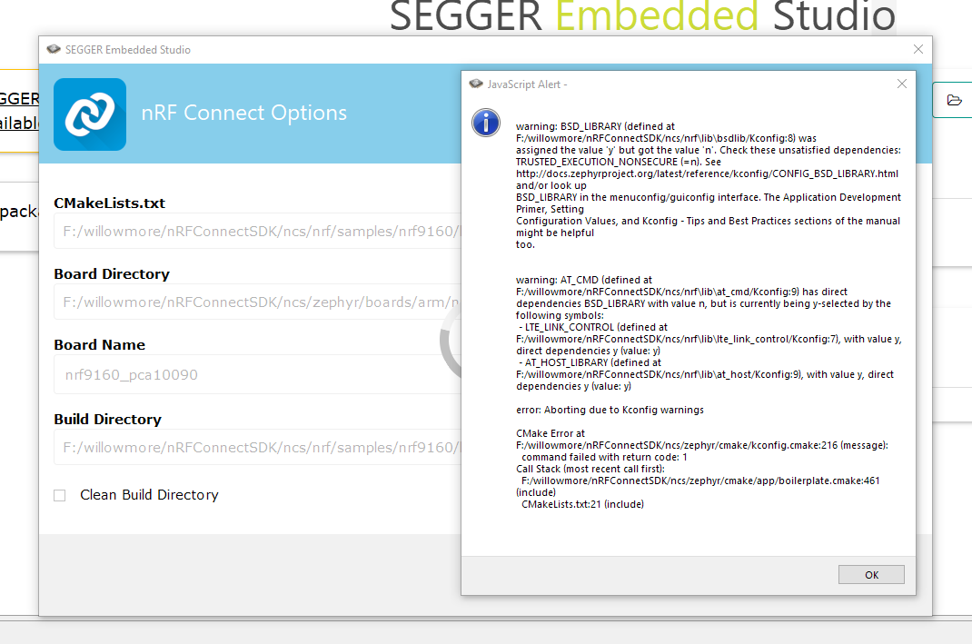
- Error message while opening a nRF Connect SDK project.
“warning: BSD_LIBRARY (defined at…….. has direct dependencies TRUSTED_EXECUTION_NONSECURE with value n, but is currently being y-selected by the following symbols: -MODEM_INFO (defined at…….”
Solution: When choosing the board name, choose one with name ending with xxxxxxns. Reason: bsdlib can only be used from a non-secure application and you need bsdlib to use the modem.
Reference: https://devzone.nordicsemi.com/f/nordic-q-a/57722/cmake-error–open-nrf-connect-sdk-project
Other good tutorial resources
- nRF Connect SDK Tutorial – Part 1
https://devzone.nordicsemi.com/nordic/cellular-iot-guides/b/getting-started-cellular/posts/ncs-tutorial—temporary#h769sk6kqovea15p99jn16lstat1dtpuuw - nRF Connect SDK video introduction
https://youtu.be/sHJTIiE2PA4
Updating the Modem firmware on nRF9160
Remember to put the switch to nRF9160 (instead of nRF52840) before the programming. You can switch and click on the “Read” button from the nRF Programmer software to check which chip the nRF9160-DK board is connected to.
The following tutorial is a good reference to show us how to update the modem firmware to the nRF9160 chip on the nRF9160-DK board.
Update Thingy91 with the latest firmware
You can download the latest “precompiled application and modem firmware” from this URL
https://www.nordicsemi.com/Software-and-tools/Prototyping-platforms/Nordic-Thingy-91/Download
Inside this package, you will see 4 folder,
- images_dfu_bin (programming nRF52840 nRF9160 chip via bin format using ???)
- images_dfu_hex (programming nRF52840 nRF9160 chip via hex format using bootloader method)
- images_full (full firmware image, programming nRF52840 nRF9160 chip firmware via J-Link debug probe/development kit)
- mfwnrf9160110.zip (modem firmware)
Let’s use the full firmware image method. Inside the folder images_full, you will see,
- thingy91_at_client_2019-11-29_d3130d77.hex (flash nRF9160 with only AT Client application)
- thingy91_ltem_2019-11-29_d3130d77.hex (flash nRF9160 with Asset Tracking Demo (connect to nRF Cloud Server for Demo purpose) using LTE-M network)
- thingy91_nbiot_2019-11-29_d3130d77.hex (flash nRF9160 with Asset Tracking Demo (connect to nRF Cloud Server for Demo purpose) using NB-Iot network)
- thingy91_nbiot_legacy_pco_2019-11-29_d3130d77.hex (???)
- thingy91_nrf52_usb_uart_bridge_2019-11-29_d3130d77.hex (flash nRF52840 to act as a USB-UART converter chip)
There are 3 firmware that needs to be updated.
- thingy91_at_client_2019-11-29_d3130d77.hex
- thingy91_nrf52_usb_uart_bridge_2019-11-29_d3130d77.hex
- mfwnrf9160110.zip (modem firmware)
They can be loaded via the nRF Cloud Programmer software.
For modem firmware, after going into the programmer software, go to the lower right side of the screen and load in the *.zip file (modem firmware). Remember to slide the switch on the Thingy91 to select for the nRF9160 chip.
For the thingy91_at_client firmware, in the programmer software load up the hex file. Then click “erase & write” to begin flashing. Remember to slide the switch on the Thingy91 to select for the nRF9160 chip.
For the thingy91_nrf52_usb_uart_bridge firmware, in the programmer software load up the hex file. Then click “erase & write” to begin flashing. Remember to slide the switch on the Thingy91 to select for the nRF52840 chip.
Playing with the nRF9160 modem
Everytime the board is plugged in, there will be 3 COM port that appears. 2x COM belongs to the nRF9160 chip, one maybe for the AT command, and the other maybe the logging messages from the modem module. 1x COM belongs to the nRF52840 chip.
Using the software LTE Link Monitor to initialise the modem and send AT command.
First connect the device, communication port by selecting the connected Thingy91 or nRF9160 device.
Some console text will starts to appear. If not, can also press the reset button on the hardware board. Key in the command “AT” to check if the board is responding to this AT command.
Key in “AT+CGMR” to check the modem firmware version.
Key on the modem command “AT+CGMR” to initalise and start the module. The indicator on the software Modem, UICC, LTE, PDN will all start to turn green.
Network will display, Singapore Telecom
For more information on AT commands for NB-IoT, refer to this page.
Flashing with AT firmware only
AT+CEREG=4
AT+CFUN=1 (connect to LTE network)
