1. How much is the electricity tariff rate costing us?
The
Singapore electricity tariff rate has been rising steadily 18.03¢ (as
of Apr 2009) to 27.28¢ (as of Jul 2011) ; A wopping 151% increase in
tariff rate. How does this tariff rate relates to the electrical
appliances that we are using at home?
The following example show you how to compute the cost of our electricity cost.
Assuming a device consuming 10W 24hr per day for one whole month.
Total energy consumption in a single day = 10W x 24hr = 240 Whr
Total energy consumption in a month = 240Whr x 31days = 7440 Whr = 7.44kWh
The bill for 7.44kWh of electricity consumption will be = 7.44kWh x $0.2728/kWh = $2.029632
This means that the appliance consuming 10W will cost me $2/mth.
Appliance consuming 20W will cost me $4/mth.
Appliance consuming 100W will cost me $20/mth.
If the tariff rate go up, the cost of electricity per watt will relatively increase as well.
What can I do to reduce my electricity bills, at the same time conserve our global energy resource?
First I have to understand my energy consumption in my own house, by doing a simple energy audit.
Being energy conscious will be the very first step to start save energy.
The energy audit of my home shown on this page will be based on the latest tariff rate of 27.28¢ (as of Jul 2011).
Calculator for computing Appliance’s Electricity Cost
2. Power Meter
The
beginning of this page starts with my handy portable power meter. It
will be the most important instrument to help me measure the power
consumption of the everyday appliances in my house. It was a
coincidence that I brought my power meter. I had always like to have
such a power meter to measure power consumption for fun and knowledge;
the cost of such a gadget was rather expensive to be purchase just for
fun. I got myself this power meter which is inexpensive. I like the
huge display; the numbers are easy to read. It is very simple to use;
just plug in the appliances that you want to measure and switched on
the power. The function button can be pressed to cycle through the list
of measurement parameters as follows.
1) Wattage, display the power consumption of the appliance
2) Display the energy consumption in terms of dollar cost
3) kWh (kilo Watt Hour), accumulated energy since operation.
4) Number of days, hours since measurement begins. (This helps to check
against the kWh energy consumed and the accumulated cost run since
measurement starts)
5) Voltage (Vrms measurement usually range from 220 – 240Vac)
6) Frequency (always 50Hz for measurement in Singapore)
7) Current (High current device usually requires thicker cable guage.
High current flowing through thin cables can generate heat which leads
to energy loss, and may result in fire.)
8) Power factor (PF range from 0.0 – 1.0. PF near to 1.0 indicates that
the appliance has a better current to power efficiency, consuming all
the power that was drawn) http://en.wikipedia.org/wiki/Power_factor
9) Highest/lowest wattage detected. (The meter when monitoring the
appliance over a long period of duration, is able to show the
highest/lowest wattage detected)
10) Key in the latest electricity tariff rate..
11) Reset button to reset the measurements.
The features on the power meter are more than enough to measure
household appliances. There is a current limit of about 13A which the
meter can handle; the meter will give off a warning beep sound and cut
of the power if it is overloaded. I just love this power meter, cheap
and good enough for my energy audit.
It was when I started measuring my household appliance, that I started
to learn the appliances that are energy consuming. It is difficult to
judge base on the device, even though I am a trained engineer in
electronics circuit design. I was shocked to find that many appliances
are poorly design in terms of energy conservation. This is also the
reason why I started this page. I would like to find out the power
consumption of the appliance in a typical home. The step to start
saving our earth starts by being aware of our energy consumption; this
is also known as our carbon footprint.
Besides measuring power consumption, this power meter is also very useful in my area of engineering works.
This
portable power meter helps to verify my electrical installation works.
There are also times where 110Vac is used in our 230Vac electrical
system in Singapore. This meter helps to check if the voltage step-down
transformer installation is correct, before we plug in any expensive
110Vac equipment from oiverseas. It can also be used to check the
wattage of your equipment so that the accessories with the correct
wattage can be purchased and installed.
Power factor
(range 0.0 to 1.0) indicates the efficiency of the current drawn from
the power station. Poor power factor is cause by your inductive
equipment (eg. Fridge, Fan, Motor etc..) at home or factory. A power
factor of 1.0 is the best, indicating the lowest possible current
drawn. A reading of 0.6PF or below indicates a poor power factor, and
you will expect the current drawn to be higher. The good news is, it
can be improve by installing a capacitor across the power line.
This
meter measures the power factor which allows me to add in the correct
amount of capacitance to correct the power factor close to 1.0. Power
factor of 1.0 means that the current drawn by my equipment will be
minimum. The meter will also show the drop in the current drawn, before
and after the capacitance installation. For more technical information
on correcting power factor, I have another delicated page explaining
all the details.
In
the course of designing products for the industries, this meter also
helps me to verify my design in terms of the energy consumption. It
helps me to improve the design, allowing the product to consume less
energy.
With this measuring instrument, we will have a better idea of how we can improve our energy consumption.
“If you can not measure it, you can not improve it.” Lord
Kelvin (1824-1907)
I hope this page can provide the awareness to get you conscious about
your carbon footprint. It will also serve as a platform to compare the
consumption with the available energy saving products. The journey
shall starts with my power meter. Let’s get started.
My portable power meter packed with many features (description details on the left). Measure power from the plug.
1) Wattage
2) Accumulated electricity expense
3) kWh
4) Records of the number of Days & Hours since measurement starts
5) Voltage
6) Frequency
7) Current
8) Power factor
9) Highest/Lowest wattage detected
10) Entering the electricity tariff rate costing.
This power meter is purchased from .
Acknowledgement: some of the pictures on this page were taken from saveOne
website. saveOne is a local company in Singapore, specialising in
energy saving products and consultation services. They are also selling
their various patented energy saving lightings products to promote
green building to the industrial, hence reducing our carbon footprint
in Singapore.
Other brand of power meter available in Sim Lim Tower (Sim Lim Tower, 10 Jalan Besar 208787)
3. Home Appliances
Power Consumption
Note: the indicated elecrical costing is using the triff rate of $0.30/kWh
This
is my electrical bill for my HDB house for the month of March 2012 from
SP Services. The power consumption is estimated to be 363kWh which
accounts to a bill of S$100.15. This is an estimation base on our
electricity consumption for the pass few months. The tariff rate is
0.2759 for this quarter Jan-Mar 2012.
I am trying
to measure all my appliances to see if I can estimate near to the
indicated consumption of 363kWh per month. The list of contribution
would propably comes from the following devices.
– Fridge
– Aircon
– Fan
– Computer
– TV and entertainment system
– Washing machine
– Lights
– Radio
The circuit breaker and ELCB or RCD device uses very little energy. No power consumption was detected.
Charger for mobile phone (5V, 0.89A)
Model: Nokia C3
Not
much power consumption when the charger is not plugged onto the mobile
phone. Measured consumption is 0W. When the charger is plugged in, the
consumption is about 1.3W.
Charger for bluetooth earpiece (5V , 0.55A)
Model: Sony Ericsson MW600
The
bluetooth charger is similar to the mobile phone charger experiment.
When the charger is plugged in, the consumption is about 0.7W.
Power Adaptor for laptop (19Vdc, 3.42A)
Model: Asus X23F 10″ laptop
For
this Asus laptop’s adaptor, the consumption is more. When the adaptor
is not plugged onto the laptop, the consumptionm measured is 0.3W,
0.014A.
When the adaptor is plugged onto the laptop, the consumption increases to 45.2W, 0.314A, 0.59PF
Then the laptop was switched on, the power consumption increases to 72.1W, 0.519A, 0.57PF.
The laptop was shutdown, and the power consumption drop back to 0.328A, 0.69PF. Should be about 45W.
Hair Dryer
Model: Rowenta (1500W)
This hair consumes a standby power of about 0.1W, 0.015A.
The hair dryer was switched to no.1, and the consumption is measured to be 755W, 3.26A, 0.98PF
Switching to no.2, the consumption now is measured to be 1460W, 6.3A, 1.00PF
This
Mini PC with power adaptor unplugged consumes about 0.5W. When it is
plugged to the mini PC, the wattage increases to 3.6W, 0.053A, 0.25PF..
When the mini PC is switched on, the power consumption is about 28-30W, 0.21A, 0.55PF
Power consumption during standby with mini PC switched off.
Food Streamer
Model: Tefal, serie S07 (760W-900W)
When
the streamer is off, power consumption is measured to be 0W. Turning on
the “Keep Warm” features consumes about 835W, 3.55A, 0.98PF. The
streamer will switch the streamer off when it reaches certain
temperature threshold. This will keep the food warm while trying to
keep the power coonsumption low.
With the streamer fully switched on, the reading is similar rto the power consumption of the “Keep Warm” feature.
LCD monitor
Model: 24″ Philips 240B MWB1240I (230Vac 1.2A)
This monitor has a standby power of 0.6W.
When it is switched on, it consumed about 27W and can reach as high as 43W.
Measurement taken 26.7W, 0.19A, 0.56PF.
Personnal Desktop Computer
Model: Shutter PC, Intel Core 2 Duo CPU E7500 2.93GHz, 4Gb RAM, 250Gb HDD, DVD drive
The
computer CPU system has a standby of 0.7W when it is plugged onto a
socket but not switched on. Typical about 60W, and the highest reading
meansured is >70W. Current is 0.361A, Power Factor of 0.82PF. When
the computer is put into sleep mode, the power consumption drop down to
3.6W 0.067A 0.21PF..
Color Laser Printer
Model: Fuji Xerox CP205W
Printer on standby 11.5W to 750W
Printer reaching its peak 776.1W.
The
laser printer standby power is about 11.4W and reaches to 750W every 10
to 20sec in a pulsing manner (0.139A, 0.33PF). Perhaps it is using the
energy to warm itself every now and then. Current 0.139A, Power Factor
0.33PF. Measurement taken during the printing process is about 50W to
750W.
A4 paper scanner
Model: Fujitsu Scansnap S510 (16V 1.5A), Power adaptor (230Vac to 16Vdc 2.5A)
Scanner
power adaptor consume 0.5W when it is not plugged onto the scanner.
When it is plugged to the scanner, the standby power is about 0.8W.
The
scanner reaches to about 17.7W (0.131A, 0.54PF) when it is turned on.
During the scanning process, the consumption is about 26.4W.
TV tuner box
Model: MyGica (5Vdc 0.6A), Power adaptor (230Vac to 5Vdc 1A)
This
TV tuner box is surprisingly using not much energy. The consumption is
measured at 0W when the adaptor is not plugged onto the device, and
reads 1.5W when it is plugged in. Turning on the TV tuner consume only
3.3W.
Water Kettle
Model: Tefal VITESSE BF21 (2000-2400W)
The water is a simple heating element device. The load is resistive in nature. When not activated, the kettle consume 0W.
During the water heating process, the power consumption measured was 2140W (9.28A,0.98PF)
Battery ChargerAA/AAA
Model: GP Power Bank GPPB50GS (230Vac 0.175mA, or 12Vdc 0.75A)
The
battery charges has a standby power of 0.7W (0.008A) when no battery is
under charging. The charging is a pulsing process. The wattage taken
pulse between 3.1W & 0.7W when one AAA size battery was inserted
for charging. The wattage goes up as more batteries (1x AAA and 2x AA)
were inserted. The pulse is between 6.9W & 0.7W (0.055A, 0.5PF)
Standby power 0.7W measured is the same as specified in the user manual. Thie meter seems quite accurate for our energy audit.
The standby power for this DVD player is 0.7W (0.008A).
When
the player starts to playback video on the CD, the measurement taken
was 6.5W (0.057A, 0.51PF). Energy consumption is quite reasonable for a
player.
It increases slightly at time to 7.2W (0.6A, 0.49PF)
The
standby power is about 4W (0.25A, 0.1PF) . When it is switched on
without any pot, the reading was 10.8W (0.141A, 0.29PF). The induction
cokker is quite intelligence. No power will be activated when the
cooking pot is not on the stove.
A
stainless steel pot fillled with water was placed on the cooker stove.
The induction cooker detects the load and starts to consume a lot of
nergy to boil the water. The power consumption was 1974W (8.691A,
0.99PF). The induction cooker power factor is surprising good. The load
may not be inductive in nature, or perhaps capacitors are added to the
cooker to correct the power factor. By correcting the power factor of
your appliances to a value close to 1.00, the current it draws will be
at its minimum. This helps to reduce losses, reduce of cable size,
prolong lifespan of your cable, generate less heat, etc…. many
benefits. The benefits will not be significant but it is better to have
it optimised than a design that isn’t.
The following footage shows how the power consumption changes on this induction cooker.
Model: Netgear ReadyNAS Duo, Power adaptor (230Vac to 12Vdc 5A)
The
power adaptor was not plugged onto the NAS, gives a reading of 0.4W.
This means that the power adaptor doing nothing is actually wasting the
electricity when connected with the mains socket switched on. When
plugged onto the NAS device, the standby power is 0.8W.
When the NAS was switched on, the power reading was 23W (0.17A, 0.53PF).
Home Wireless Router
Model: Dlink DIR-655 (12Vdc, 2A)
Wireless router’s power consumption seems ok. Measured power during operation was 6.1W (0.051A, 0.51PF).
AV Wireless Transceiver
Model: AV@AirPro
This wireless AV transceiver consume about 2W. Quite little energy.
Cable TV setup box
Model: STARhub Hubstatio DC162SHB
The
STARhub setup box has a significantly high standby power required. The
measured power during standby was 20-25.6W (0.184A, 0.59PF).
The
setup box reaches 27W (0.187A, 0.6PF) during start up, and consume
26.5W (0.19A, 0.59PF) during the cable TV show. The increase in power
from standby is relatively low. This device has the most energy wasted
during standby. Turning the machine off to a standby mode will only
save you 1 to 2W, but actually wasting about 25W.
The
little multimedia Zen10 box consume much less energy compared to the
STARhub setup box. Zen10 consume only about 0.4W during standby, and
6.2W (0.052A, 0.42PF). If the power adaptor is not plugged onto Zen10,
the wasted power on the adaptor is measured at 0.2W.
Fridge
Model: MITSUBISHI
The
fridge consumption seems rather stable. Different from what I have
expected. I thought it should be like a pulsing type of power
consumption pattern. Switching on and off the compressor when neccesary
to cool the fridge. Typical wattage consumption was about 209.1W and
can reach as high as 388.7W.
The meter was put on the fridge for another period of 32 days. The following reading was taken which was more accurate.
Wattage at the point in time: 204W
Current at the point in time: 1.126A
Power factor at the point in time: 0.78
Lowest wattage detected: 17.3W
Highest wattage detected: 440.5W
Voltage range: 228.9 to 230Vac (50Hz)
Total measurement period: 31days and 23 hours
Total energy consumed: 149.1kWh
Total electrical bill amount: $44.73 (base on electricity tariff rate $0.30/kWh)
I
was shopping around to take a look at the latest energy efficient
fridge. The consumption for these fridge as displayed was about
500-700kWh per annual. The efficient is much better. I am assuming the
measurement was took without considering the typical scenario of
opening of the fridge door. Opening the door increases the temperature
inside, which means that more energy is required to cool it down.
Washing Machine
Model: National NA-FSSY6T
Washing machine standby power is 1.3W – 1.8W (0.006A, 0.42PF)
Filling up the washer with water consume 8W (0.038A, 1.00PF)
Washing
process rotate the motor clockwise and anti-clockwise. The consumption
is pulsing between 100W and 340W (0.7A and 1.4A 0.19PF). The power
factor becomes lower when the motor starts to be activate. Motor is an
inductive load causing the power factor to becomes lower.
After the washing process, the washing machine drained the water. This activity consume only 4.8W (0.021A 0.85PF).
The
washing machine starts to spin to squeeze out the water. The machine
controls the spin. I can see the wattage moving slowing from about 230W
to 260W as the spin starts to pick up. When the spin reaches its
momentum, the wattage starts to drop gradually to 200W. At top spin the
wattage is about 200W. The initial start up requires more torque to
spin the load, therefore more power was required. When the spin reaches
it top speed, the torque required was less, therefore less power was
required. This activity consume an average of about 230W for 2 min.
The
whole washing process takes about 45min to 60min. Total wattage consume
is about 0.352kWh for two wash (medium load). This comes up to about
0.176kWh of energy consume for each washing.
Oven
Model: TEFAL Turbo Delice 26L
My
mother was baking the pineapple tarts for Chinese New Year, when I took
this measurement. I wanted to find out how much electricity is used to
bake the tarts.
The tarts were baked at about 180°C for
about 20 minutes. A total of 7 trays (36 pineapple tarts per tray) were
baked in 4 batch. The cost of electricity is $0.42. This means that the
electricity cost for each batch of baking cost about $0.105, each tray
cost $0.0525, or each pineapple tart cost about $0.0015. The bill seems
quite affordable.
Wattage at the point in time: 2900W
Current at the point in time: 12A
Power factor at the point in time: —
Lowest wattage detected: —
Highest wattage detected: —
Total measurement period: 1 hour 20 minutes
Total energy consumed: 1.431kWh
Total electrical bill amount: $0.42 (base on electricity tariff rate $0.30/kWh)
Soldering Iron
Model: GOOT TQ-95 Quick Heat Soldering Iron 200W/20W
When the soldering iron is first switched on, the wattage measured is 60W.
As the iron gets heated up, the temperature starts to drop to a constant wattage of 25W (0.1A, 1.0PF)
There is this quick heat button to heat up the iron faster (can only press for no longer than 10sec).
When this button is pressed, the wattage shoot up to about 128W (0.523A, 0.98PF).
The soldering iron is a resistive load, which is why the power factor is always quite close to 1.0PF.
Cost of running the soldering iron for 1 hour = 25W/1000 x 1hour x 0.30kWhr = $0.0075 (about 1 cent every hour)
Conclussion:
– Top energy consuming devices
–
Many switching AC-DC power adaptor do consume energy when it is left
switched on. The power factor from all these advance switching adaptor
seems quite poor.
Keyword:
Power meter, energy consumption measurement, energy audit, energy saving, save energy, ECO friendly
The IC chips, active
and passive components are all connected by traces or wire. The traces
on the PCB are assume to be of short circuit, which is 0Ω. This assumption is reasonable if it
conduct a very small amount of current. When the conductor starts to
carry larger amount of current, the voltage drop across the trace could
be significant, causing intermediate hardware problem.
If you are expecting a large current flowing through the
traces, you have to keep in mind to provide a wider trace to increase
the conductivity of the cable. Larger trace width means lower
resistance.
For my PCB route software, the defined trace width for power
is 1.27mm and signal is 0.38mm. Sometimes there is a need to route the
trace through narrow space. In this situation, I would have to use the
recommended trace width for power min, and signal min. Usually I will
keep this narrow trace as short as possible to avoid higher resistance.
Seldom do I need to worry about traces carrying signal
information. I am more worried about the conductor distributing the dc
supply to individual circuit zone. Whenever possible, I would provide a
wider traces for my 5V and ground supply.
When designing the PCB routing for my power supply, I would
use the star topologies. This will ensure a evenly spread for the
current distribution, hence lowering the burden of individual traces. I
have actually experience such technical issue during my final year
school project. The noise problem is somehow reduce after the attempt
to improve on the trace routing. Another experience involve power up a
remote system about 10m away. The distance is quite near and the power
cable is rather thick to me. The voltage at the remote end is found to
be too low to power the remote system. We have to double the cable
conductor in order to resolved the problem. Our equipment conduct high
current of about 20A if I remember correctly. The problem might not be
obvious because the high current being drawn might happen during
certain hard to determine event. For example, when your system trigger
the lightings or motor which draws very high current for a short period
of time. The voltage drop cause by the sudden high current draw might
cause your system to fail. Therefore the design should always cater for
the worst case. Always find out the maximum possible current drawn.
Over design the system to ensure that the system will not fail in the
worst case scenario. Just to make a note, that I have been referring to
dc voltage supply.
For high voltage AC supply, I guess it is a different way of
looking at it. My understanding in high voltage system is quite weak.
On the left is the reference table to estimate the resistance
of the trace for my PCB routing. I have assume the worst case at
temperature 100˚C with the copper
layer of 1oz thick. Seldom do you need to refer to this table, unless
you have encounter space restriction for your high current carrying
traces. It is my usual practise to double the current carrying
capacity. 2 times the maximum current I will be expecting. If you have
the space, make it wider.
I have also provide the computation for copper resistance for
your reference. Taking this opportunity to do further read up in order
to explain in a simplified form.
Area is the cross sectional area of the conductor. Just like a
water pipe, the larger the cross sectional area, the easier the current
is able to flow through.
Resistivity defines the resistance of the material for a unit of length
at a certain temperature. The resistivity for the material copper at 25˚C is found to be 1.7×10⁻⁸Ω.m
The resistivity changes with temperature. The resistance will
increase as the temperature increase. The term for this changing
resistivity with temperature is known as the thermal resistivity of
that particular material.
The material resistivity would therefore look like a graph
curve. They are obtained through test and experiment. For some
material, the graph curve could be approximated in the form of
equation. This complicated formula describe the resistance behavior of
the material under different temperature condition. For copper
material, it can be represented from the following equation,
Copper resistivity = ρ0(1+α(Temperature-T0))
= 1.7×10⁻⁸Ω.m
x (1 + 3.9×10⁻³Ω/˚C x (100˚C-25˚C))
= 2.2×10⁻⁸Ω.m
at a temperature of 100˚C
<ρ0 is the material
resistivity at T0 temperature>
As you can see from the
calculation on the left, the increase in temperature from 25˚C
to 100˚C has increase the 0.1m
copper trace by 0.06Ω. This is about 30%
increase in the resistance.
To keep the topic simple, we will not go into the details of
varying temperature. There can be other factor that can affect the
resistance of the material.
Here
is a quick and simple graph showing the change in temperature in
relation with the trace width and the current flowing through it.
(taken from the magazine elektor 2010-02). The graph assume the pcb
copper trace thickness to be 35um (1oz) & that it is place in a
open air environment (not enclosed inside a box/casing). For example,
given the trace width of 0.6mm, and a 1.5A current flowing through it,
we can expect the copper area to rise by another 10°C.
I have put up this wire gauge guide for my own
reference. Very often there is a need to return to this reference to
choose an appropriate cable for use. I have also written an article
some time back. Myth about how the cable relate to their resistance. It
is taken out from the main webpage but I have place a link here, for
anyone who are interested to understand more.
NOTE: The following guideline is a brief
guideline for copper ampacity (current rating or current-carrying
capacity) of the cable used for power supplying purpose. The
ampacity is defined as the maximum current the cable can withstand. Any
current higher than that will generate enough heat to burn away
the cable. There are many factor affecting the current capacity of the
cable, and it should be compensated accordingly. I would advise to
select the cable, with at least double the current-carrying capacity
for the intended equipment. Never operate near the cable
current-capacity limits. You will never know when, the current
overruns. Some of the factors that will affect the current-carrying
capacity of a cable are:
–
Conductive wire cross section area.
–
Wire material. The temperature the material can withstand without
melting out.
–
Temperature. If the wire/insulator jacket can withstand higher
temperature, the cable is able to carry more current.
– place of installation or the surrounding
temperature.
– material of insulation jacket/skin/cover.
– how much the cable can dissipate heat
–
Stranded or solid wire type. Stranded wire can carry more current than
a solid wire for AC type of signal/power. This is due to a phenomenon
known as skin effect.
The factors involve are quite complex. The table
is a simplified reference for myself to select the cables. Always allow
a larger safety margin of minimum x2 when you chose your cable. Do take
careful note of what you deploy.? There are many other factor, eg screw
connections, plug contact which will affects the results. If the cable
has the slightest warm, it is quite clear that the cable will be
hitting it’s limit any time soon.
Wire Cable
Description
Diameter
(mm)
Area (mm2)
Copper
Resistance 20˚C.Ω/km
Nearest SWG
gauge (mm)
Nearest
AWG gauge (mm)
11.68
107.2
–
–
0000
10.4
85.03
–
–
000
9.266
67.43
–
–
00
8.252
53.48
–
–
0
7.348
42.41
–
–
1
6.543
33.63
–
–
2
5.827
26.27
–
–
3
5.189
21.15
–
–
4
230Vac power cable 16mm2 (absolute maximum 69A)
eg. Sub
Mains
4.620
16.77
–
–
5
4.115
13.30
–
–
6
230Vac power cable 10mm2 (absolute maximum 52A)
eg. high
power showers, cookers & other very high power devices
3.665
10.55
–
–
7
3.264
8.366
–
–
8
230Vac power cable 6mm2 (absolute maximum 38A)
eg.
showers, cookers & other high power devices
2.906
6.634
–
–
9
2.588
5.261
–
–
10
230Vac power cable 4mm2 (absolute maximum 30A,
6.9kW)
eg. low
power electric shower
2.305
4.172
–
–
11
2.00
3.10
5.47
14 (2.05)
12 (2.05)
1.90
2.80
6.05
230Vac power cable 2.5mm2 (absolute maximum 23A)
1.80
2.60
6.76
15 (1.83)
13 (1.83)
1.70
2.30
7.57
Wire
copper enameled, Pro-Power ECW1.5. current rating 2.74A
eg. power
speaker, transformer, motor
1.60
2.00
8.54
16 (1.63)
14 (1.63)
1.50
1.80
9.7
230Vac power cable 1.5mm2 (absolute maximum 16A,
3.6kW)
1.40
1.50
11.2
17 (1.42)
15 (1.45)
1.30
1.30
13.0
16 (1.29)
230Vac power cable 1mm2 (absolute maximum 13A,
2.99kW)
eg. for
light circuit
1.20
1.10
15.2
18 (1.22)
1.10
0.95
18.1
17 (1.15)
Audio cable (shielded), Belden 8760
eg. power
speaker drive
1.00
0.78
21.1
19 (1.02)
18 (1.02)
0.95
0.71
24.3
0.90
0.64
26.9
20 (0.91)
19 (0.91)
0.85
0.57
30.2
0.80
0.50
34.1
21 (0.81)
20 (0.81)
0.75
0.44
38.9
0.70
0.69
44.6
22 (0.71)
21 (0.72)
0.65
0.33
51.7
22 (0.64)
0.60
0.28
60.7
23 (0.61)
0.55
0.24
72.3
24 (0.56)
23 (0.57)
Wire Cable
Description
Diameter
(mm)
Area (mm2)
Copper
Resistance 20˚C.Ω/km
Nearest SWG
gauge (mm)
Nearest
AWG gauge (mm)
Category 5E network cable, 8060-OZZ7FNL from
Alcatel
Special material for conductivity connection. Some references
for non-traditional or advance conductor materials.
I happen to see some special wire product that I
think I should put them in this website for reference.
The follow shows a rubber strip (a black layer
sandwich in between the two white layer). It is call the elastomer
connector. It is typically used to connect a flat LCD display panel to
the pcb board without any soldering. It is quite cool when it was being
shown to me for the first time. The LCD and pcb is connected with this
elastomer connector sandwich in between.
Elastomer
connector
(soft rubber strip that can conduct like a wire)
Conductive fabric or cloth
this pic is tken from other website
The conductive fabric actually can feels like a
typical cotton cloth material. Some other feels like a nylon fabric, a
bit like plastic. This is great for RF shielding, which we used it to
test the performance of RF transmission through various material.
Earphone + Microphone:
Pin 1- Left Speaker
Pin 2- Right Speaker
Pin 3- Mic+
Pin 4- Ground
iPhone Mobile Phone Earpiece: Samsung Galaxy Samsung Nexus S
Pin 1- Left Speaker
Pin 2- Right Speaker
Pin 3- Ground, Push Switch
Pin 4- Mic+, Push Switch
Nokia Mobile Phone Earpiece:
Pin 1- Left Speaker
Pin 2- Right Speaker
Pin 3- Mic+, Push Switch
Pin 4- Ground, Push Switch
3.5mm 3pins
Commonly use for:
– Earphone
– Speaker
Earphone/Speaker pin out:
Pin 1- Left Speaker
Pin 2- Right Speaker
Pin 3- Ground
Notes:
Speaker’s load is inductive. Measuring the resistivity from the pins
will usually yield very low resistance (near to short circuit).
Measurement by probing the pin in reverse will yield the same result.
Microphone pin out:
Pin 1- Mic+
Pin 2- Mic Power
Pin 3- Ground
Notes:
Commonly available electret microphone contains active components. The
positive terminal of a microphone can be detected using a ohm meter.
Measure Mic+ (+ve Probe), Mic- (-ve Probe) will yield a higher
resistivity than probing the reverse way Mic- (+ve Probe), Mic+ (-ve
Probe).
Electret microphone equivalent circuit
Other type of microphone:
– The Carbon Granule Microphone
– The Piezoelectric Microphone
– The Condenser Microphone
– The Dynamic Microphone
– The Ribbon Microphone
– The Hot-Wire Microphone
Walkie Talkie pin out:
Pin 1- Mic- / PTT Switch common
Pin 2- Mic+
Pin 3- PTT Switch
Pin 4- Speaker+ (left)
Pin 5- —unused— (right)
Pin 6- Speaker-
Mini DIN plug 6 pins (male pins)
Known to be use for:
– Walkie talkie
Walkie Talkie pin out:
Pin 1- Mic- / PTT Switch common
Pin 2- Mic+
Pin 3- PTT Switch
Pin 4- Speaker+ (left)
Pin 5- —unused— (right)
Pin 6- Speaker-
Pin 1
Mic- / PTT Switch common
Re
Pin 2
Mic+
Bk
Pin 3
PTT Switch
Wh
Pin 4
Speaker+ (left)
Ye
Pin 5
—unused— or Speaker+ (right)
Bl
Pin 6
Speaker-
Gr
Mini DIN plug 4 pins (male pins)
Commonly use for:
– S-Video
– Walkie talkie PTT switch connector
Walkie Talkie pin out:
Pin 1- —unused—
Pin 2- —unused—
Pin 3- PTT Switch
Pin 4- PTT Switch
Mini DIN plug 4 pins (female pins)
DIN 5 pins
Known to be use for:
– Bike’s audio connector
Bike Audio pin out:
Pin 1- —unused—
Pin 2- —unused—
Pin 3- PTT Switch
Pin 4- PTT Switch
DIN 7 pins
Known to be use for:
– Bike’s audio connector
Bike Audio pin out:
Pin 7- PTT Switch (White)
Pin 3- Speaker L
Pin 5- Speaker R
Pin 2- Speaker Gnd
Pin 4- Mic-
Pin 1- Mic+
Pin 6- Mic shield
DIN 8 pins
GX16 Aviation plug and socket connectors (16mm)
FD-M16 16mm Connectors
Nanaboshi Connectors
(panel mount)
NJC series (general metallic connectors/socket)
NR series (twist lock connector, one-touch lock mechanism)
NJW series (waterproof panel mount connectors/socket)
The objective of this site is to get to know about the electronics
components that can help us control 230Vac devices. Devices like ac
lamps/lightings, power sockets/supply, heater, and many many other
appliances at home. We are all surrounded by many appliances operating
directly from AC mains supply. It is very interesting to control and
work with these appliances. Learning to control with electronics,
microcontroller and computer.
Our home is typically pre-installed
with 230Vac sockets. The socket where we obtain our electrical power source. It
is this basic utilities that keeps us operating in this urbanization era. Different country
implement their own
AC voltage system &
AC plug. The electrical delivered
to our home wall socket is a 230Vac
single phase ac power. So throughout the section, we will only talk about single
phase system and not the three phase system.
The first thing in my mind when it
comes to 230Vac is “Dangerous”!!! I am still very scare of it. One careless mistake and we might
not have a second chance to try again. Some article suggests that a voltage over
30V is considered as danger. Lower voltage is relatively safe to touch with your
bare hand, although sometimes you may get the shock sensation on your muscle.
230Vac is a dangerous stuff, but when working with electronics you can hardly
avoid using it. And when we cannot avoid it, then we have to face it. Facing it,
by understanding more about it. Minimizing our chance of getting killed by
230Vac. So let us pay careful attention to this section.
The following article is from a
website with simple illustration of electrical safety. It explains in simple
terms the difference between birds and human touching the same high voltages
cable. Why birds don’t get
electrocuted? How do we get electrocuted? From these two question, we get to
understand more about voltages and how we should deal with them to protect
ourselves. Safety first, which is why I put this as the first section.
Remember that we will not have any chance to try again. Understanding the
danger of electrical earth path will minimize the chance of getting
electrocuted.
Before touching any wire, be sure to
measure and ensure that there are no “live” voltage on the wire. You can use a
multi-meter or test pen to check for live connection.
Multi-meter.
Measure between the “live” and “nuetral” line to check if 230Vac is present.
Test
Pen (this test pen comes in the form of a slotted screw driver. You can see a
small bulb embedded in the handle. Touch the suspected “live” wire with the tip
of the screw driver. Locate the back of the handle for a metal plate. If the
bulb inside the handle lit up, when you touch your finger to the metal plate, it
means that the wire is “live”.
Various names: Electrical box, DB box, Electrical distribution panel,
Control panel
On the left are some of the common electrical box that we may find
in our home. They are the main electrical distribution point to all the
other rooms. From the power station to the sub-station and then to this box,
distributing electrical power to our rooms.
This
Type-G
plug distributed to our rooms, consist of 3 cable namely Live (hot, brown),
Neutral (return, blue) and Earth (safety ground, yellow/green).
On the electrical box, we can see a row of switch. One main switch is
particular unique in color or size. This is the main switch which cut off
the supply from live and neutral wire. The rest of the switches, only the
live wire is disconnected. This is an important note to take, and the same
applies to the wall switches. When we switch off the light or appliances,
only the “Live” wire is disconnected.
There was once I was working on a power supply unit. Wanting to doing
rewiring, I switch off the power leaving the 3 pin plug on the socket. I have carefully
unscrewed and pull out the earth wire. Thinking that it is now safe that I have
switch off the AC socket, I
become relax and casually removed the earth cable. The earth wire
accidentally touches the neutral wire and phow, my whole office got black
out. From then on, I remember that neutral wire is as alive as the live
wire. Never treat it lightly. When you switched off the power to do
maintenance work, do not assume that the live as well as neutral is
disconnected. Always check and handle them with care. Insulate the bare wire
if you are unsure. Assume that they are always alive, unless you are
absolutely 100% sure that the wire is unplugged from the power system. 99%
is not good enough. It has to be 100%.
MCB (miniature circuit breaker) to protect the electrical line from over
current drawn. RCB (residual current breaker) similar to MCD is another
protection device trips when electrical leakage is detector (incoming
current != outgoing current). Some device has both the features of MCD & RCD.
They normally comes in the standard DIN rail mounting for the electrical
boxes.
Other name: ELCB, MCCB, RCD, RCCB, RCCD (residual current circuit
breaker), ground fault circuit interrupter (GFCI), ground fault interrupter
(GFI) or an appliance leakage current interrupter (ALCI), safety switches, “salvavita”
(life saver).
Power Distribution Components, MCB, RCB, Switches
It is recommended to install a circuit breaker (MCB) as well as a residual current
breaker RCB when working with AC devices/equipments under test. They can protect
against accidental over current or leakage fault that occur. Anything goes
wrong, the device will be tripped, cutting off the power supply from the
mains, protecting us from possible electrical shock.
RCB is more important
as a protection from serious electrical shock. During normal operation, the
current to and from the live and neutral wire should be equal. Any different
in current indicates leakage. The device detects the leakage and trip the
supply source.
MCB is more to cut off supply on overloading load. Example
would be a short circuit from a faulty equipment. If the supply is not cut
in time, the huge current pumping through will heat up the cable, resulting
in fire along the cable.
There was once I am working on an automated swing
door system. I try to cover back the aluminum cover, but find difficulty
putting it back in position. Not knowing why there was this small gap,
I bang on the cover trying my luck to close it up. Suddenly I felt a very
loud bang and bright light flashes over me, followed shortly by a slight
breeze. They were the result of the small explosion.
After investigating,
I found out the the casing actually cuts through the AC cable resulting in a
short circuit. The cable were not properly secure in a safe position and the
cover finishing is badly done. The edge will not filed and has a very sharp
edge. It is lucky that I remembered to connect the earth wire to the
aluminum cover, else I would have being shocked. So as you see, it is
important to earth the metal surface that are near the AC line.
The MCB is
found to be tripped, and some burn mark can be seen around the place of
impact. The MCD is trip almost instantly, but the 3 pin AC plug for the
automation door is still badly burned. When I open up the plug, the interior
is completely burned out. Wire and fuse all black with carbon. I have to
spent another hour to repair the cable & plug, tied the cable in place,
smoothen the cover edges. A lesson to learn. Proper installation not only
protects ourselves and it also minimize re-work.
In this scenario, the
earth wire and MCB have done their job very well. You may have installed
these protect in place, but without proper knowledge of how they are going
to protect you, you are just as vulnerable. Learning how to protect yourself
is the most important.
A normal electrical switch. (no protection function)
lockable switch for tagout purpose
The switch on the left may looks like MCB or RCD. It function as a simple
single pole switch, and offers no protection at all. They are typical used
to disconnect the live wire inside the electrical box, switching off the devices just like a wall
switch.
Some models comes with a lockable design, for user to tagout. This is to
minimize any chance of people unknowingly switch on the power, when the user
is doing the maintenance work.
Single Pole MCB explain Curve Types
Surge current can be higher than steady state current, especially for
inductive/capacitive load. Eg. motors. The surge higher than the
current limit set, can easily trip the MCB. This means that it can be
difficult to switch on a motor for example, because a surge from the
motor startup can easily trip the circuit breaker.
This call for special MCB which has a wider allowance for surge
current. MCB comes in various curve type, each has its torlerrence for
surge current.
The photo on the left shows 3x MCB type (red color lever) having a
circuit breaking current of 10 amphere, namely B10, C10, D10. Each of
them has the same current limit. The type B, C or D curve indicates
their ability to withstand sudden power on surge current.
MCB type B curve – Can
withstand a surge current of about 3-5 times its rated current limit.
For this MCB B10, the rate current limit is 10A. So this means that the
MCB can withstand up to about 30-50A of surge current within the
initial millisecond time.
MCB type C curve – Can withstand a surge current of about 5-10 times its
rated current limit. For this MCB B10, the rate current limit is 10A.
So this means that the MCB can withstand up to about 50-100A of surge current within the initial millisecond time.
MCB type D curve – Can withstand a surge current of about 10-20 times its
rated current limit. For this MCB B10, the rate current limit is 10A.
So this means that the MCB can withstand up to about 100-200A of surge current within the initial millisecond time.
There is another single pole MCB B16 in the picture. This MCB breaks
the circuit when the current is over 16A. The MCB is of type B, meaning
it can withstand the initial surge current of about 48-80A.
Industrial safety practice
When servicing AC socket or
equipment, ensure that the AC source at the electrical box is switched off. If
possible, unplug from the AC socket.
Lockout/Tagout procedure should be practice
strictly. This is important when we work outside because we may not be the only
person operating the equipment. Lockout/Tagout involve locking and tagging the switch source. So you
can be sure that no other people can switch the power back on, when you are
working on the socket or equipment. It is a safety procedure. If you do not have
the facilities to lock out the power, a sign board or labeling warning is
advise to prevent any accidental switched on.
For your own safety, the procedure is worth the trouble.
Some signage references,
As what I have experience, AC power is actually quite dangerous. It is very
important that you equip yourself with the knowledge and know-how to protect
yourself against any electrocuted accident. Safety is the most important.
Always treat it as through it is the first you have touch it.
Singapore Customized, custom made Electronics Circuits & Kits
There is once I wanted to measure the AC signal using my oscilloscope from
the mains. I am curious to look at the sine wave from the wall socket mains. Tack,
all the offices around me had their power tripped.
I made a Mistake?….. I don’t even know why? I was lucky that I
took extreme precaution during the measurement.
It is then that I started to re-visit 230Vac to understand more about it. I
realized that our oscilloscope ground clip is actually connected to the
earth as reference. Which is why the power trip, when I clip the ground lead
to the neutral line. When this earth clip touches the neutral wire, the extra
electricity leakage tripped the MCB (Miniature Circuit Breakers) found
inside our electrical box. This is a safety feature to protect us. So
remember that the Earth line is connected to the ground lead of the
oscilloscope probe. Be careful.
Does this means that we cannot measure the ac waveform using the
oscilloscope? How do we do the measurement then?
From what I found out, there are various methods to measure. Differential
method to measure the AC signal would be more appropriate. Two probe would
be required, placing across the signal you ant to measure. Ground lead can
be floating, which the reference is earth because the ground lead is
connected to the earth line. The difference between the two probe channel
would be the actual AC signal. With help from the typical oscilloscope
feature, the signal can be obtain as a single waveform ploy on the screen.
One of the channel need to invert (using the INV function), and both the
channel are added (using the ADD function).
Seldom typical engineer like us need to examine the AC signal. Those
power engineering people who wanted to measure the signal probably wanted to see
the harmonics to check up on the quality of the power supply. Or perhaps, as
curious as I am, just wanting to see it.
Measuring the mains using digital multimeter. Reading is 230Vrms
The waveform of the AC mains 230Vac 50Hz is shown in
red.
The signal we should see on the scope…. (click to enlarge)
The most frequent used equipment for measuring our 230Vac mains would be
the multi-meter. Portable and inexpensive. Providing us the basic
measurement for
checking the wire voltage. The power is quite reliable in urban area, always
maintain it’s voltage reasonably at 230Vac. Probably a test pen can be the
only measuring equipment you need.
When we measure the ac mains from the socket using the digital
multi-meter, we will get a reading of 230Vac or 110Vac (depending on the
country you are in). Take special note that this reading is effectively the rms (root mean square)
voltage. The actual peak voltage of the electrical line go up to about
325Vpeak. The 325Vp (peak) sine wave is equal to 230Vrms.
Vrms = √2 x Vp.
230Vrms = 0.707 x 325Vp.
Vrms can be think
as the equivalent voltage in dc for power computation. The actual AC power (sine
wave in red) has the
same energy as one that is illustrated in the Vrms
view point (square wave in blue). The energy
can be computed, and they are defined as the area under the waveform. Area
under the square & sine wave is equal. I
have draw out the waveform to illustrate the idea.
Keep in mind the peak voltage. It would be useful in helping you select
the proper component. Capacitor is one of such component where the
capacitance and voltage rating is the main criteria for selection. Voltage
higher than what the it can take, the capacitor will experience voltage
breakdown. Pop, the capacitor can have a mini exposion.
So do remember, the AC mains is in fact 325Vp (peak) or 650Vp-p (peak to
peak). That is very high voltage!!!
Yes. Now
that we get our theory clear, let’s get on to the real hands on.
Date: 2009-08-01
This is one of the most exciting experiment that I ever done. Ever since my
first disaster measuring AC mains, my understanding of oscilloscope and AV
mains remains very unclear.
Every step is carefully think of, carefully executed. This is unlike any
other new electronics circuit that I want to experiment with.
Any minor doubt that I have, I will research on the internet to confirm my
understanding before I connect up the circuit.
It feels to me like experimenting with dangerous explosive.
One mistake, either my life at risk,
or my expensive digital oscilloscope gets damaged.
It is the most detailed experiment that I ever done.
For an experience engineer, this can be as easy as ABC.
For a first timer like me who have never measure the 230Vac line,
and no senior to guide me, this is really frightening yet exciting.
I am sure we will have a better understanding of high ac voltage, with this
step by step measurement guide. Dealing with 230Vac will eventually be as easy as ABC.
So let me starts this exciting experiment.
NOTE: Click
on the image for a clearer view.
My
measurement setup for measuring the output of the zero crossing triacs
circuit. A detail
connection of this setup is shown in the following section.
The picture on the left is the setup that I have prepare for the 230Vac
signal measurement.
Equipment used in this measurement experiment
– 3 pin extension socket
(protected by RCD device)
– Triacs switch circuit
– DC power supply (to activate
the triacs circuit)
– AC fan (device to be controlled
by the switch circuit)
– Oscilloscope (Tektronix TDS
2014) and probe.
– Some wires for connection.
My triacs switch circuit. This switch circuit is solid
state relay. Just like a mechanical relay, the circuit interface helps
digital control circuit to control a 110/230Vac mains devices. There is a AC
input and the controlled output as shown by the green wire terminal.
Click here for further detail information on this circuit on another page.
Probe ground crocodile clip is clip onto the
oscilloscope Earth pin. The measurement for Live/Neutral signal is with
reference to the Earth potential.
The circuit that I am going to measure is the output of a AC switch
circuit presented on the left. The circuit using a triac component to switch
the AC power. If you are interested to find out more about this circuit, you
can visit the following page I have put up.
The following summaries the steps taken in order to do a proper
measurement.
1) All the equipment for the experiment is powered from the RCD (residual
current device) protected extension plug. This is to protect myself in case
I accidentally touches the live/hot wire. The RCD will cut off the power in
the case of power leakage through my body.
2) Connect up two probe from the oscilloscope to the circuit. CH1 probe
is connected to the Live wire output, while CH2 is connected to the Neutral
wire. The ground clip of the probe should be connected to the oscilloscope
Earth pin. You should able to see such a pin on your scope with the
Earth/Ground symbol (see the photo on the left). This is the setup for
measurement with reference to the Earth ground. This Earth pin is internally
connected to our 3pin AC socket. Therefore the pin is the same as our 3 pin
plug Earth. The grounding clip from the oscilloscope is found to be Earth,
so in fact there is no need to connect up. For clarity and safety reason,
just connect it up. Always ensure that your oscilloscope is properly Earth
for safety reason.
3) Set the probe attenuation to 10x. On probe there is a switch labeled
1x and 10x. 1x means that the probe signal is exactly feed into the scope.
10x means that the signal will be attenuated to a factor of 10 times before
feeding into the scope. The scope may not be aware of the attenuation, so it
is important to setup the scope for the 10x measurement. If this is not
done, you will find that the reading is 10x smaller than expected. A 10V
signal will be read as 1V. It is not important but will be clearer if you
just set it on the scope. The signal is expected to see on the scope should
be a 325V. After attenuating the probe, only 32.5V is actually feed into the
oscilloscope input. Tektronix TDS 2014 oscilloscope can accept signal up to
300V. Without the attenuation, the scope might just blow up. Although the
scope received only an input of 32.5Vp, it multiple the scale by a factor of
10 because of the settings I have done on the scope.
4) The reading is going to be very high, so set the voltage div for both
CH1 & CH2 to the max. In my case after adjustment to the 10x factor on the
scope, my max setting is 50 volt/div.
5) Set the scope to Math function: CH1 – CH2. CH1 is measuring the Live
signal with reference to Earth while CH2 is measuring the Neutral wire with
reference to Earth. In order to measure the signal Live with reference to
Neutral, we need the scope to do some math, CH1 – CH2. (A red trace appear representing a new
trace CH1 – CH2). Disable the CH1 & CH2 trace so that you can see only CH1 –
CH2 trace clearly.
6) Ensure that all wire is properly screwed and secure. Pull individual wire,
and ensure that it does not comes off.
The oscilloscope presents the signal at the output of the triacs switch
circuit.
The AC mains power is not switch on to the triacs switch circuit
yet, so no signal is detected at the circuit output..
Once I switch on the mains switch, some small noise is detected at the
output of the circuit. The triacs is in the off state but some signal is
being observed. This means that there are some leakage. The leakage is ok
because it is too small to activate the AC fan.
The triac switch is activated and the 230Vac is observed at the output. Yes,
this is the 230Vac. But there is a problem. The voltage is too high for the
oscilloscope to display. My scale is to 50 volt/div, and I have only 8
division on the y-axis for display. This means that I can only measure in
the range of 200Vp-p. The reason for the signal clipping on the display.
To display the full 230Vac range or 325Vp-p. We need to attenuate the signal
more. Some probe you have the option to attenuate by 100x.
Measurement with voltage divider across Live & Neutral
wire.
My probe only allows me to attenuate the signal by a factor of 10. I will need to attenuate the
signal further.
For my case, I have a voltage divider using 2x 1MΩ
(0.25W), to attenuate the signal by two times before feeding the signal to
the probe. The voltage divider is connected across the output terminal of
the Live and the Neutral wire. CH1 is connected to the divided voltage
(between the two resistor), while the CH2 remains connected to the Neutral
wire.
You can use other resistor value
but you need to ensure that the resistor wattage is able to handle the high
voltage. The maximum voltage across the Live/Neutral is 325V. If 2x
1MΩ is used for he voltage dividing, the
maximum current expected will be about 0.16mA. The minimum wattage required
is therefore 325V x 0.16mA = 0.053W. I have used a 0.25W resistor, which is
more than enough. If you are using 2x 10kΩ resistor divider, make sure your
resistor wattage is at least 6W. There will be more current flowing through
the resistor, more energy dissipating across it, and it is going to be hot.
A lot of energy is wasted if you use lower resistance.
The left present the actual measurement setup with a voltage divider
circuit to attenuate the signal so that the oscilloscope is able to display
the high voltage.
Remember to multiply the voltage by 2 times while you
analyze this waveform. This is because the voltage has been divided by 2 due
to the voltage dividing circuit. Click on the photo to enlarge the signal
650Vp-p at 50Hz, representing our 230Vac mains supply.
Finally a clear 230Vac waveform display with a period of 20ms. I finally
managed to measure the 230V mains.
On the scope, the signal display about
320Vp-p, but in fact the signal is actually about 640Vp-p. This is because
of the voltage divider that I have added and the scope just have no idea
about it. So mentally, you need to multiply by 2 to get the correct reading.
This is about the same as what we have computed previously. 230Vrms has the
actual waveform of 650Vp-p at 50Hz. Any capacitance component attached
across the Live & Neutral wire have to withstand at least the voltage of
325V. This is important for our component selection.
After this write up I have better confidents in dealing with 230Vac and it’s
electronics.
Something that I often used and understood little about it.
It is so interesting.
If only I am as curious when I am in school during my teenage days.
There would be many teachers to guide me in the understanding.
As a teenagers, most of us probably be fooling around
rather than learning seriously and actively.
Wanting to learn and know more than what the lecturer teaches.
I hope you have enjoy, and get a better understand in dealing with 230Vac
measurement.
Measuring current by inserting the meter into the current path.
Measuring the AC current using the clamp meter. Easy, just clamp
it.
How much current is being drawn from your wall
socket. You might probably want to know how much energy your
equipment/appliances is consuming.
For measurement of current, a cable clamp
meter is recommended. Clamp measurement detects the invisible alternating
electrical field generated by the 230V ac 50Hz. No contact with the copper
wire, just clamp around the cable. This is all about Faraday Law, founder
Michael Faraday. It is actually very interesting learning about the
history of how people actually discover these physics. They are great
people. I watched a very interesting science history documentary. A documentary about the history and
concept behind E=mc2. I think it would be great to share you
everyone.
Do a search on,
“E=mc2 – Einstein and the World’s Most Famous Equation”
a mini current sensor for AC power line. Comes with 1:300, 1: 500, etc… transformer coil ratio
Measuring Current using a current sense coil or transformer
The
picture on the left is a mini current transformer. To measure the
current flowing through your AC power line, either a “Live” or
“Neutral” wire has to be put through the hole located in the centre of
the sensor.
The sensor consist of fine wire coil inside.
The coil is wind around the circular core, forming a ring to sense the
AC magnetic field around the AC power cable through the hole. It is
important that only the “Live” or “Neutral” wire can be inserted
through the hole. If both the “Live”and “Neutral” are put through the
hole, the signal will be minimum. This is because the magnetic field of
the out going wire will be cancel off by the returning wire.
The picture on the left is a simple setup with the oscilloscope probe to the two terminal on the current sensor.
Note that only 1 wire (Neutral) through the hole on the current sensor.
Signal
at the output of a 1:300 coil transformer, while powering up a sprindle
motor. The motor load is an inductive load. The current signal being
pick up is quite noisy from the motor. The signal is about 5Vp-p.
Signal
at the output of a 1:300 coil transformer, while powering up a
soldering iron. The soldering iron is a heating element which is a
resistive load. The current signal looks like the 230Vac 50Hz sin wave
at about 0.2Vp-p.
This
is a rectified signal (using diode bridge) picked from the sensor. The
power line is not powered up, no load. I thought it should be flat. It
could be noise generated from other nearby appliance through the
“Neutral” wire.
The signal seems weird, but I did not investigate much on this result.
Ch1 is the rectified signal picked up by a 1:300 current sensor. The motor load is being switched on and off.
Ch2
is the signal conditioned through a LPF (low pass filter) and an op-amp
comparator circuit. A clean result showing the motor being on and off.
Ch1
is the rectified signal picked up by a 1:500 current sensor. The motor
load is being switched on and off. As you can see, the magnitude of the
signal being picked up is higher. A higher voltage output, is being
trade-off with a lower current drive. Since the signal will be
conditioned by an op-amp, having a low current drive is not much of a
problem.
Ch2 is the signal conditioned through a LPF
(low pass filter) and an op-amp comparator circuit. A clean result
showing the motor being on and off.
Computing Appliances Electricity Usage
Now that we measured the current consumption,
I am starting to be curious on the power consumption for a typical home.
Just for the fun of it, I have investigate some of the high power
consumption appliances.
Energy (Wattage) = Voltage (Vrms) x Current (Ampere)
Energy meter to measure power consumption of your electrical
appliances.
How much does my power cost?
Energy cost: S$0.1803/kWh as on 16 Jun 2009
Energy cost: S$0.2558/kWh as on 1st Apr 2011
Energy cost: S$0.2728/kWh as on 1st July 2011
This means that it cost S$0.1803 running an appliance consumption 1kW
for an hour.
See more energy measurement at another webpage Energy Audit
Air King Model 9106
Energy: 57-77Watt
Energy consumption for 8hr/day= 77W x 8hr = 616Wh
Energy consumption for 30 days = 616Wh x 30 = 18.48kWh
Energy cost for 30 days = 18.48kWh x $0.1803/kWh = $3.33
Energy for a Fan will cost about
$2.47-$3.33 per month
Daikin Inverter Multi Split (R-22)
Energy: 1520-6900Watt
MSZ-FB series
Energy: 2500-5000Watt
Energy consumption for 8hr/day= 6900W x 8hr =
55.2kWh
Energy consumption for 30 days = 55.2kWh x 30 = 1656kWh
Energy cost for 30 days = 1656kWh x $0.1803/kWh = $298.58
Energy for a Fan will cost about
$65.77-$298.58 per month
MR-560U 560 litre Refrigerator
Energy: 570kWh/year
or 65W when I divide that number
with 365 days x 24 hours
Energy consumption for 8hr/day= 65W x 8hr = 520Wh
Energy consumption for 30 days = 520Wh x 30 = 15.6kWh
Energy cost for 30 days = 15.6kWh x $0.1803/kWh = $2.81
Energy for a Refrigerator will
cost about
$2.81 per month
Philips MASTER TL5 circular fluorescent lamp
Energy: 22-60W
Philips
PL-T compact fluorescent bulb
CFL, compact fluorescent
Energy: 32-42W
Energy consumption for 8hr/day= 60W x 8hr = 480Wh
Energy consumption for 30 days = 480Wh x 30 = 14.4kWh
Energy cost for 30 days = 14.4kWh x $0.1803/kWh = $2.60
Energy for a fluorescent lamp
will cost about
$0.95-$2.60 per month
Energy consumption for 8hr/day= 42W x 8hr = 336Wh
Energy consumption for 30 days = 336Wh x 30 = 10.08kWh
Energy cost for 30 days = 10.08kWh x $0.1803/kWh = $1.82
Energy for a fluorescent lamp
will cost about
$1.38-$1.82 per month
Incandescent
Light Bulb
Energy: 50W
Incandescent seems to have similar wattage with the fluorescent. In
fact a 15W compact fluorescent can have the equivalent brightness of the
50-60W incandescent bulb. Therefore using fluorescent can be cost saving.
The energy cost matches quite well with my home monthly electrical bill. I
am quite surprise that the fridge use so much less energy. Did I make any
wrong assumption? Now I also aware that the energy to turn on the aircon for
a day, is enough to operate a fan for 3 months.
=
End of the fun. Let us start to research more about the AC ingredients
available.
See more energy measurement at another webpage Energy Audit
Singapore Customized, custom made Electronics Circuits & Kits
The list on the left are namely some of the common components used for
controlling 230Vac appliances.
This section is closely related to switching. So I decide to divert your
attention to the switch. The range of components for controlling your
appliances. It is all about “Switch“…
So let’s move on to learn more about switch.
AC to DC conversion (Transformerless)
Our electrical system uses high AC voltage to distribute energy to our
homes. Most gadgets works with DC voltage, therefore we often see a
AC-DC circuit module as part of the gadget.
Some AC-DC module are integrated into the product; for example, our
computer, DVD player, radio. Some AC-DC module comes in the form of
power adaptor that supply DC voltage to the devices.
The AC-DC module is so common, it will be useful to learn about them.
Most AC-DC contains a transformer to isolate the DC voltage from the AC
mains. This acts as a form of protection, so that people will not get
electrocuted when touching the DC circuit.
There is also a newer type of AC-DC using switching method. It is
something similar to switching DC-DC method. The transformer used can
be alot smaller. You can see that old power adaptor was heavy and
bulky. The power adaptor nowsaday are light and small.
Another type of AC-DC module uses only resistors and capacitors,
without any transformer. They are also known as transformerless AC-DC
circuit. You need to be careful when handling this type of cicuit as it
is not isolated from the AC mains. You will get electrocuted touching
the DC circuits. Please refer to the section above
to understand more about 230Vac and how one can get electrocuted.
Transformerless circuit is simple and cheap, and it is suitable for
application that consume low power.
This
circuit converts 230Vac to 4.6Vdc without using any transformer. Please
take note that the circuit is not isolated from the 230Vac mains;
ensure that the circuit is enclosed and properly earthed to prevent
accidental electrical shock.
(Last update: 31 Oct 2010)
Example: Transformerless 230Vac to Vdc (for a load of 24Vdc 20mA)
This
circuit converts 230Vac to Vdc suitable for a 24V 20mA load, without
using any transformer. Please take note that the circuit is not
isolated from the 230Vac mains; ensure that the circuit is enclosed and
properly earthed to prevent accidental electrical shock.
(Last update: 12 Jan 2011)
Another transformerless circuit 230Vac to 5Vdc that I found on the internet. (I have not tested this yet)
AC-DC integrated circuit product manufacturer
You can refer to the datasheet on their website for the datasheet and application notes.
High efficient ac-dc conversion IC
– isolated (smaller transformer component)
– non isolated (transformerless), LNK306DN
2018-10-31 Transformerless Power Supply – 230Vac to 12Vdc
quick release connector (no need to screw on the wire)
Pluggable 3 way connectors from wieland, commonly used for connecting
electrical AC cables to lightings lamp. The connector can be
pre-installed onto the power termination point and the mating connector
on the lamp component. This simplifies the cable to lamp connection and
allows faster installation.
History, old telephone exchange in New York City,
during the year 1910.
Switch
Story
Long long time ago, circuit connection is achieved using muscular means.
The telephone network is one of a major communication system in the early
days. To Call your buddy next block, the first step you have to do is to pick
up the phone. A human operator will attend to your pick up. Speak to her
about the intention to talk to your buddy. The operator will manually plunk
in wire connector linking your home telephone to your buddy phone. And Yes,
you can now talk to your friend because there are operator doing the
switching at the end of your telephone line.
Sounds a lot of manual work. Yes, this is the good old days. The telephone
operators in the central telephone exchange house, are making the circuit
connection manually. This is what this page is all about. All about switches.
All about making a good short circuit.
Not all short circuit is bad. In fact they are the fundamental building
blocks in digital electronics. Many electronic design/interface are as simple
as a switch.
In the articles that follows, it will be about the various type of
electronics components that can help you in the creation of the perfect short
circuits.
Various type of connectors
The following connector guide
present the typical name for various connectors.
Other
Type of switch characteristic.
*ON-OFF
*(ON)-OFF
ON-(OFF)
ON-ON
ON-(ON)
ON-OFF-(ON)
*ON-OFF-ON
*(ON)-OFF-(ON)
* means most common configuration
(xx) means momentary position,
no bracket means latch position,
off means no connection between throw,
alternate action switch is similar to a momentary switch, but the state
will get alternate/latch when the switch releases to the spring back
position.
Switch Type (for switch with 2 or more throw)
non-Shorting (typically) – contact is break first before making contact with
the next contact.
Shorting – contact is short with the next contact, before breaking with the
previous contact.
Various product that uses switches
Mechanical
switches is a simple type of interface to control electrical stuff using the
means of some mechanical action. In short, a switch is a mechanical to
electrical conversion device.
I can’t find any history on the evolution of the mechanical switches. I
guess people might have become smarter. Rather than using a jumper wire to
make connection manually, human invented switch to make short circuiting task
more efficient. Tedious and time consuming work. Plucking the wires in and
out takes a lot more effort, compare to toggling switches.
Of course mechanical switches are not suitable for telephone exchange
application for the millions of household. However understand the roles of
switches in electronics, will definitely increase our awareness for a more
complex electronic system. Switches in the form of mechanical, digital
circuit, power electronics are commonly use in the electronics design.
The greatest thing to understand about switches is all about the
component/device rating. Some people refer it as the power handling capacity,
which is the voltage and the current. The voltage it can handle across the
switch terminals without destroying itself. Sometimes refer to as the
breakdown voltage. The maximum amount of current that can flow through,
without destroying itself. Sometimes refer to as the load current the switch
can support.
In fact, the whole idea of this “switch” thingy is about
understanding the rating and capabilities of the various type of electronics
components. I mean it applies to all the electronics devices, including even
wires. To me, this is also the most important concept towards understanding
of all other electronics. It is so important. Fortunately it is also easy to
understand, if you pay enough attention in this topic.
Not just switch have rating. Wire also have it’s rating, since we know
that switch is in fact another form of wire, or to be precise we call it a
conductor.
Like the size of a water pipe, there is a limit on the water flow rate. If
the pipe diameter size is small, flow rate will be small too. Larger diameter
pipe more water can flow. This is what they mean by the term “current
rating”. Larger wire size can carry more current. Small wire may also
carry the same current at the expense of increase temperature. When it gets
too hot, the wire will just burn off, just like what a fuse do.
For further information on choosing your wire for carrying power, click
here.
If there is an important message that I want you to bring back after
reading this whole article, it will be the following four words.
“Everything have its Limit”
Shifting our attention back to mechanical switch. There are various kind
of terms for mechanical switch. Switches can be “momentary” meaning
the the switch will spring back to the original position when there is no
external push forces, or “latched” meaning that the switch will
stay at it’s new toggled position when when external push forces is applied.
Switch description such as“double poles double throws”
or 2P2T provide more information on how the switches are operated.
“Poles” tell us how many sets of switches are connected to a single
mechanical trigger. This is often refer to as ganged switches.
“Throws” describes the number of switch contact way. If you are
still not clear what I mean, refer to the pictures on the left side. Picture
indeed tells a thousand words.
Another term used is shorting or non-shorting switch. Non-shorting switch
means that the switch will break the contact with the current
“throw” position before making contact to the next
“throw” position. This type of switch is more commonly in use.
Shorting switch means that the switch will break the contact with the current
“throw” position after making contact to the next “throw”
position. This means that during the switching, two of the “throw”
position will be shorted for a very short period. It is used where the
connection needs to be connected always and not left floating at any one
time. Happen to found out that these are used in switching loads such as
loudspeakers, where the source cannot be safely operated without a load.
There are other form of switch description known as the “switch contact forms“,
some example are Form A,
B, C, X, Y, Z, AA, BB, AB. Form A is defined as a normally open switch,
while Form B is a normally close. Form X is similar to form A except that it
has a double break contact. Form X, Y, Z are double break switches.
For example a switch labeled as “Form 1A” (SPST) indicates that
it is a 1 pole normally open switch. “Form 2C” consist of a NO as
well as a NC contact, also known as the DPDT or 2P2T switch. Form Y is a
normally close 1P1T double break switch. Form AA is a 2P1T normally open
switch.
These terms are common description for mechanical switches, and is
also widely applied to mechanical and reed relay devices as well.
The main point to note when choosing a switch, is on the mechanics design,
and the feel of the button. This is non-technical, and is more about user’s
experience.
Technically all switch has their maximum rating for handling current. Like
a wire, if you choose a thin and fine wire, the wire will get burn or melted
when large current flow through it. This is also the principle of how
electrical fuse works. You can choose a higher rating switch which can match
most type of condition, however they are usually big and bulky. This is the
trade-off on choosing an appropriate switches.
There are many more styles of switch, and you may like to refer to the
following website for more references.
There are various mechanical switches around us. They are acting as a
system interface, which convert mechanical motion into electrical signal. For
example, the keyboard which you are typing, the power switch that turns on
your TV, the keypad you pressed on your telephone or mobile phone, the lever
switch that turns on your rice cooker, microwave oven….etc. They are
interface with switches for us to control.
Interfacing
a switch for digital input (TTL, CMOS)
The circuit on the left illustrate a simple switch interface. This
interface provides a output voltage to indicate the status of the switch. If
the switch is press, the output will be a 0V. While it is release, output
will be a 5V. This can be a input interface to a digital circuit, for logic
‘1’ or ‘0’. A useful and basic circuit interface.
Mechanical Glitches from a mechincal switch
Mechanical switch is analog in nature. When a mechanical switch is
pressed, two metal plate is in contact with one another. The force is small
but is large enough to cause the contact plate to bounce away.
This is like a pencil dropping onto a floor, we can see the pencil hitting
the floor and bounced up. The pencil will settle on the floor after a number
of bounce.
This bouncing results in intermediate contract between the metal, and can
be catches very quickly by the electronics. This also results in what is
known as the switch glitches.
This is not too critical for some electronics, but for others, it may
result in undesirable results. Designing a mechanical switch which is
glitchless can be difficult. A practical way to remove the signal glitches
would be through electronics components and design. Microcontroller is very
popular in most circuit design, and the firmware can also be written to
remove these unwanted input switch glitches.
The oscilloscope’s screen capture on the left shows the glitches produce
by the following PCB mounted tactile push button switch.
The signal captured is the input signal, when the push button is released.
These glitches can sustain its noise for as long as 5-15ms. The slower the
switch is release, the longer the glitches can be generated.
The glitch behavior depends very on the mechanical switch design. There
are switch which can produce a clean digital on/off signal. However, it is
best not to assume that the noise will forever not appear. It is still better
to assume the possibility of generating noise to design your input circuit
properly.
A simple way to remove such switch glitch noise is to insert a capacitor
of let say 100nF between the input signal and reference ground.
Common
Switch Information (name, dimension, circuit)
Toggle
Switch (chasiss mount)
Toggle switch dimension and thread size 1/4-40 UNS-2A
Drill 6mm hole for tapping.
This
is a very important section. The introduction to this electrical control switch,
call a Relay. It is basically a device to activate a mechanical switch, by
electrical means. This is unlike a switch which is activated manually. In
another words it is a device that convert electrical signal to a mechanical
energy back to electrical signal again. Similar to mechanical switch, they
can be described as 2P2T, single pole double throw, etc…
How it works? A electrical voltage will be applied to activate a coil in
the relay. The coil being powered up, will generate a magnetic force that
will attract the lever. This lever will be pulled towards the magnetized
coil, causing an action that will switch the mechanical contact.
Why on earth this relay is for? Why is there a need to convert electrical
to mechanical to electrical again?
A example would be that you may want to switch on your home 230Vac power
remotely from your friend house 1km away. To do this, one possibility is to
lay cables thick between your friend’s home and your home. The cable must be
thick enough to handle the high current and 230Vac voltage. Using a 230Vac
rated switch, which is relatively bigger in size, it can be mounted in your
friends home in order to do the switching.
Another cool method is that you can deploy a relay to help switching the
230Vac in your own house, while a thinner wire and lower rating switch laid
across your friend’s house. This is one of the use of a relay. To be exact,
the relay helps to control energy from a electrical signal to a mechanical
energy to electrical power. Other application can be, controlling a high
power motor using tiny switch, or to switch on the house lightings using your
computer system digital signal.
The application of relay is important, as it is still widely used in
control application. It can be thought of as a amplifier. A powered signal
can be produced by using a small signal. This principle is similar to the use
of a transistor as a switch. Knowledge in the relay will certainly aid
understanding the transistor, commonly seen in circuit interfacing.
Example of
an electrical circuit using a relay
There maybe times where you need to activate a relay, for certain logic
output. The digital signal from the logic IC might not be able to turn on the
relay coil. This is because the logic IC are not design to drive load that
requires high current. To drive a high load device such as a relay or motor,
a transistor can be interfaced between the logic and the supply to power up
the load. The following diagram illustrate the circuit. More information
about using a transistor as a switching device, can be found in the later
section “Transistor“
(fig.3a)
Digital Logic interface to a Relay as output using transistor.
Another common use of relay is to act as a isolator output for
communication or I/O between unknown electrical system. This isolated output
acts as a mean for electronic hardware to communicate without affecting
another electronics system. System design will be simpler, while
integration/troubleshooting work will be easier and faster, because system
can be isolated easily.
For example, one company may have a robotic application which require
mobility and high current discharge. A 12V SLA sealed lead acid battery would
certainly meet this requirement. A mobile phone company is following the
market trend and will be designing a 3.3V electronics circuits which has the
advantage of size and energy efficiency. Another one may choose to deploy 5V
system, because they have been using some critical component which requires
5V. How are their design able to communicate or control another system using
a different voltage system. They may use communication standard like RS232 to
communication between systems. However the design will be considerably too
complex if the communication requires only 1 bit of information, either on or
off.
The operation of a relay as an isolated output is simple. The system X
that activate the relay provides a switch contact to indicate logic 1 or 0 to
the receiving system Y. Y provides its own power and interfacing circuit to
sense if the switch is close or open. Since there is no voltage interaction
between the two system, some people defined this as a “Dry Contact interface”.
System X activating the relay has provides a “Dry Contact” or a
switch contact output without any electrical signal transmitted to system Y.
Dry contact does not mean that no electrical current flow. It simply mean
that Y will provide it’s own electrical circuit to obtain the output signal
from X. For further information on detecting switch status, you can refer to
the section on mechanical switch.
In this scenario, the relay acts as a output isolator, providing a logic
signal without any direct interference to the receiving system Y. Y will
interpret the switching action, just like a normal mechanical switch.
Implementing such a isolated design, it makes the system modular just like a
black box. Certain input will be responded by a defined output result. On
site deployment will be easier, and system troubleshooting can be a lot
faster.
The important points to note when choosing a relay is to purchase the
correct coil voltage rating, and the relay’s switch current handling
capacity. When the coil is to be activated from a 12V signal from a circuit,
you need to get a relay that can be trigger by 12V. There are various input
rating typically 5V, 6V, 12V or 24V to choose from. Remember to take note of
the voltage system your electronics circuit is running, before any relay
purchase. On the switching side, you need to determine how much current will
be flowing through the relay. If you need to turn on a high current rated
device, make sure you get a relay that can handle the maximum current/power
the device can draw from the supply. As a guide, choose a relay switch that
have a current rating 2 times the maximum expected current that will be
drawn. This would be quite a safe margin to prevent further complication due
to temperature or other environment factor. A higher rated relay switch will
be bigger. It is a trade off to decide upon. Cost ranges from S$3 to S$20.
Relay can wear out and need replacement. There are socket available, so that
the relay can be plug in and out for replacement easily. They are available
for about S$5 to S$10, with choices like DIN rail mounting, PCB mount, etc…
Compare to current known technology, the relay is able to provide a higher
current handling capacity, and higher isolation between system.
The disadvantage is that relay have relatively shorter operating life due
to mechanical wear and tear. It also make tick tack noise produce by the
mechanical action. The switching could also produce unwanted mechanical
glitches. When switching high voltage power, because of the large voltage
difference between both end of the contact, arcing will be produced during
the switching. This arcing spike can weld the contact bit by bit, and after a
period of time the contact can eventually be welded together. The relay will
then be useless since it is unable to do switching. Therefore the mechanical
relay component is unsuitable for switching high voltage power line.
Although there are a number of disadvantages, it is quite popular because
of the ease of using it. Troubleshooting is a bit easier because you can hear
or see a relay operating. Unlike a semiconductor devices, measuring instrument
or indicator display is require as an aid to troubleshooting.
Reed
relay is a smaller version of relay. Package is in plastic. It is about the
same size as a 14 pin DIP IC socket. It has a slightly different magnetize
structure, however the principle is the same as a mechanical relay. Since it
is small, this reed relay is suitable for handling signal, and not high power
or high current drawing load. Switching sound is hardly noticeable. You can
still be able to hear some tick tick sound when it is activate. Switching
speed is considerable faster than a relay because the switch mechanism inside
the package is small.
Application for a reed relay can be for output signal isolation purposes
or for switching on small current load. Example of small load devices that
can be switched on might be LED, DC buzzer, relay, circuit or sensors.
Typical current handling capacity is of about 0.5A load.
Reed relay comes in different type of forms. Forms refers to the nature of
the switch contact. For further information on “contact forms”,
refer to the switch section above.
Typically swtch form is a single pole single throw switch (SPST or Form
A), Typical input coil voltage is of about range from 3V to 12V. Load
coil current is typically 10mA for a 5V reed relay. Cost is about S$2-5
A number of time I encounter product issue with the reed relay, and have
to spend a lot of time de-soldering the component out for a replacement. I
will recommend building a simple tester to test the reed relay.
For a 1A05 relay, the coil resistance is typically 500Ω. Some new
reed relay can measure 500Ω, but after pumping 5V across the coil, the
resistance might drop to 100-300Ω or even 0Ω. This might be due to
the faulty coiling wire which go shorted inside the reed when the current is
applied. Once the short occur, power supply may experience the short circuit.
Fuse or transistor in the circuit may get damage due to the short. The output
contact of the relay might not work properly, and should be checked as well.
Some part number that you can refer to, for Reed Relay products. Part no.
description example “1A05” means the relay is of forms 1A, and is
activated by 5V.
This
is newer switch device known as Solid State Relay (SSR) or MOSFET relay. It
is a semiconductor device, to replace the mechanical relay as a reliable
alternative. In solid state relay, the input and switched output have voltage
polarity. Be careful not to connect to the wrong terminal. Some SSR are
design to have the same package and pin layout design as a reed relay. It
looks like a reed relay. You can differential between a reed and a SSR device
by testing it’s input terminal. A reed relay is able to function with a
reverse input priority, however a SSR will not be able to function with
reverse input priority.
The solid state relay can be smaller than a mechanical relay. It is a soft
start device and does not result in current slug or arcing effect. It has no
mechanical switching and is able to do faster switching. This mean that there
are no noise, no glitches mechanical switching, lesser wear and tear. All
these advantage adds up to longer lasting and more reliable device. The
device works with a wider range of input voltage (typical 3V to 12V) and
consume relatively less power to turn on the switch.
Like other semiconductor devices, they do have their disadvantages. The
component have current leakage when inactive and dissipate heat during
operation. Heat sink may be required to prevent overheating. With a heat sink
mounted, the whole design could be a lot larger than the mechanical relay
alternative. The heat sink itself can be up to 5 times the size of the SSR.
If you don’t want to mount the huge heat sink to the device, you can try
using a SSR that have a much higher current rating, of at least 2 times the
capacity of what is required. At least it will not be very hot. If possible,
mount it to a metal chassis or metal surface to act as a heat sink to
dissipate the heat.
There are various model of SSR in the market which can take AC load
230V/150V and there are models that can handle up to 12Vdc 40A power. Price
ranges from S$5 to S$150, depending on the requirement for the load rating.
You may try visiting Crydom or Clare for more information on these devices.
In today’s competitive market, semiconductor product advances very
quickly. Greater performance design might have been already out in the market
at this point in time. You can try searching around for new products to keep
in touch with the current technology. Free Electronic
Engineering Times magazines from Global
Sources, provides good information on technology trends as well as the
latest electronic product that is rolling out onto the market. It is very
likely that the semiconductor devices model for example, solid state relay,
integrated circuit IC, transistor, that are presented on this page might be
already behind time.
Some part number that you can refer to, for Solid State Relay,
- LH1500AT, VO1400AEF, VO14642AT

- LH1535AAB, LH1535AT (DIP-6 or SMD-06 package, 1 Form A, Vmax 400V, I max 0.12A, Ron max 25 Ohm)

reference: http://www.vishay.com/solid-state-relays/


  FOTEK
- SSR-25 DA (current leakage 3-5mA)


  Leakage Current problem with solid state relay

In an ideal condition, when the input to the solid state relay is activate, the output will turn on, when there is no input, the output should be completely turn off.

In practise, solid state relay output do have some little current flowing, even when the input is not activated.

This little current is also known as a leakage current.

When connected to a big load, this current leakage will not cause any problem,

because the small current will not be able to activate the load.

Example of such a load can be a motor or heater.


When the same solid state relay is connected to a small load, for example, a LED, a lamp indicator, or an energy saving light bulb, the small leakage current can be enough to activate the load.

For LED indicator load, the lamp will be constantly turn on. For energy saving lamp, you may notice that the lamp is flickering.


In order to remove this leakage current, a load can be permanently connected across the output, so that this leakage current can be consumed.

A load can be a AC fan, motor, AC step down transformer, high wattage resistor etc... to remove the leakage current from the solid state relay. When connected in parallel with the indicator, the indicator will not be lighted up.

This is because a significant portion of the leakage current is supplying to the new load. This channelling of current, means that there are less current flowing to indicator.

If this current is low enough, the LED will not be lighted up. The significant portion of the leakage current will be flowing to the new load.

Since a fan/motor load cannot be activated with a small leakage current, nothing can be observed.

Leakage current problem will not become obvious to a typical user. To be precise, the little current probably consumed and converted to heat on the load by a tiny tiny bit.


Using a load across the solid state relay can help to dissipate the leakage current. It is a load which waste energy doing no work. More energy will be wasted when the solid state relay is in the on state.


A typical resistor load also known as "bleeder" resistors", can help dissipate the leakage current. According to many other reference it could be 22Kohm 1/2 watt to 30Kohm 1W.

Heat will be generate. Be sure to compute with a matching resistor wattage. My computation is about 23Kohm 2 to 3W.


Leakage current is due to the snubber networks (R-C circuit across the output used to improve the commuating for inductive load).
Singapore
Customized, custom made Electronics Circuits & Kits
Resemble circuit between the transistor and switch
(fig.6a)
typical transistor interface, as a switch. Acts a voltage or signal
converter, also known as a level shifter.
(fig.6b)
switch interface function resembling fig a.
(fig.6c)
opto-coupler interface.
(fig.6d)
resembling opto-coupler interface, compare fig c.
Using transistor as a switch to drive high current loads
(fig.6e)
Digital Logic interface to a Relay as output using transistor.
– npn transistor “BC549” to drive up to 0.1A
load
– npn transistor “2N3019” to drive up to 1A load
– npn transistor “tip31a” to drive up to 3A load
(fig.6f)
same transistor setup to drive a motor.
The switching setup to drive the coil load On/Off, can generate
“spike voltage”. This is due to the sudden On/Off switching from
the transistor. The same applies when replacing the transistor with a
mechanical switch. A diode can be connected across the inductive coil load to
divert the spike voltage away from the transistor, as shown in the following
diagram. This diode has a name known as a flyback diode. The spike voltage
can be high enough to damage the transistor (exceed the transistor’s
breakdown voltage).
Transistor is often found to be permenantly short circuit, if the flyback
diode is missing, disconnected or not working. Another symptom could be
transistor is permenantly opened circuit, which happens after some time being
short circuit. The short circuit current could probably burn up the shorted
conection.
(fig.6g)
flyback diode typically 1N4148 (for small current rating), to divert the
spike generated by the inductance away from the npn or n-ch transistor. Refer
to diode
selection guide for higher current rating.
(fig.6g)
flyback diode to protect a pnp or p-ch transistor
Analog Devices, IRF (International Rectifier), MAXIM, National
Semiconductor
A switch is a mechanical to electrical conversion device. Transistor is
similar to a relay. It converts between electrical system. A voltage logic of
0V 3.3V is able to convert to and from 0V 5V. A voltage logic of 0V 12V is
able to convert to and from 0V 9V.
Transistor can be used as a switch or as an amplifier. A transistor as an
amplifier needs more brain power. In this section, we will only discuss on
using a transistor as a switch. Simple lesson.
As you might have know already, the transistor is actually a semiconductor
device. In general, it is a conductive device. Transistor is a variable
conducting switch. If you can still remember the main topic of this article.
Yes. It is all about switch. Transistor is also a form of switch. The
fundamental understanding of using/choosing a transistor, is in fact very
similar to selecting a switch or wire. In this section “Transistor as a
switch”, you should always
think of a transistor as a switch. Think of it in the way that
transistor can be a substitute for a switch. The switch can be a substitute
for transistor. Compare between the transistor and switch, you will see a
clearer picture of the transistor operating like a switch.
When I first learn the term transistor as a switch, I didn’t understand
what my lecturer is trying to say. After some experience with the transistor,
I finally become aware and understand that what the book is trying to say.
The subject is title “transistor as a switch” for a reason. We have
to think of it as if it is a switch.
Similar to a relay, the switching action of the transistor can be
activated from a voltage input. Sufficient voltage input to the base of the
transistor will make the collector and emitter terminal saturated, also known
as Vce(sat). In another word, the collector and emitter terminal will be
almost shorted like a switch. Technical it means Vce(sat)=0. In practise,
Vce(sat) will never reach 0V. It will be slightly higher than 0V, for
example Vce=0.2V. Fig a, shows a typical schematic for a switching
transistor. This is very similar to the switch interface in Fig b.
Resistor R1 is chosen so that sufficient current is supplied to the base
of the transistor. In most cases 1kΩ would be ok. Over driving the
input will burn off the transistor, while under driving will not provide
enough current to switch the transistor to fully saturated. For example, an
input 3.3V is to turned on the transistor. Assuming the transistor parameter
has a turn on voltage Vbe of 0.7V, with minimum requirement Ib
of 2.6mA for terminal Vce saturation to occur. R1 should be chosen not more
than 1kΩ “(3.3V-0.7V) / 2.6mA”. Any resistor greater than
that, will not be able to provide enough current to turn on the transistor. A
resistance too low for R1 will results in higher current, though likely to
damage the transistor. Refer to the transistor datasheet for appropriate R1
value, or you can do a quick experiment to determine the R1 value to
implement.
The design value for R2 resistor should be considered based on the input
devices the switch signal will be feeding to. A low resistance value for R2
(example: 470Ω) consume more energy. This is because more current will
flow through the resistor when the transistor switch is turned on. A higher
value R2 (example: 10kΩ) conserved energy, however input response may be
slow for certain charging devices. Example would be a ADC (analog to digital
converter). The input signal requires faster charge-up/discharge for sampling
to take place. A higher R2 will reduces the current and slow down the sample
& hold process.
I seldom do computation on transistor when it is used as a switch. When
you get used to it, you will get to understand the behavior of this component
and eventually understand the computation of a transistor.
Typical
transistor circuit acting like a switch. The control signal is from a low
current supply IC (for example a microcontroller).
More information
For pnp transistor, the concept is the same as npn transistor. When do we
used it? When your logic depends on positive voltage as a reference to switch
on the transistor.
To understand this further, you need to realized that a single wire has a
potential voltage. But exactly what the voltage is, you will not be able to
define it.
This concept is like what I understand from the teaching of Tao. Tao is a
Chinese philosophy teaching. Take for example, a wooden stick in my backyard
garden. Some people say that the stick is long. But how long would you
consider it as long. Compare it with the paper clip on my desk, it is long.
Compare it with the river flowing down to the sea, the stick is too small to
be seen. The fact is when we say the stick is long, we are comparing it to
something we have in our mind. Comparing to a reference point is the key. The
relative difference is the key concept.
This is the same as the voltage potential on the wire end. The open end wire
has a potential. When we want to read the voltage of the wire, we are
actually reading it with reference to another potential. The difference
between the two potential is the voltage being read out. To know what is the
voltage is on the wire, we need a reference point. Assume we read a voltage
of 5V with reference from a ground potential. We will read the same wire as
-7V if our reference is on the 12V potential. The voltage level is a very
relative thing. Comparing to another ground reference, the voltage might be
100V. Voltage is relative. The same open end wire can be 5V, -7V, 100V at the
same instant of time. This is because the reference used in each measurement
is not the same.
To turn on a transistor, you need to provide a voltage difference between
the base & emitter. You need 2 point to turn on a transistor. Only a wire
to the base will not turn the transistor on. You need a pair of wire. One
wire to the base, the other wire to the emitter terminal.
PNP has its emitter terminal on the positive end, while npn has its
emitter terminal on the negative end.
Given a voltage system of 5V & Gnd (0V). If I have a logic 5V which I
need to use it to switch on a transistor. For this case, I can use Gnd as the
reference. Between this logic 5V and Gnd, is a voltage difference which can
be applied to the transistor, to switch it on.
If the reference I used is a 5V. The logic 5V will not be able to switch
on any transistor devices, because the voltage between logic 5V and reference
5V is equal to 0V difference. A transistor will need a voltage difference for
it to be switched on. Typical textbook voltage is 0.7V which is our Vbe.
Reference line to be connected to the emitter terminal. Logic or signal line
to be connected to the base.
Now we know that we have logic 5V & reference 0V. We know that npn
transistor would be the component for this switching on job.
Given another situation where you have a logic 0V signal which you want it
to switch on your transistor. The voltage reference should be 5V. Present
voltage difference to the transistor would be -5V. PNP transistor is chosen
this time.
Another illustration to looking at a npn & pnp transistor is to look
at the arrow on the transistor symbol. The potential of the arrow head should
be lower than the arrow tail by typically Vbe 0.7V. Voltage difference can be
more than 0.7V but base resistor should be present. The resistor is there to
absorb all the unapplied voltage, so that Vbe can be maintain at 0.7V. If no
base resistor is present, the base current is so large that the transistor
will be damaged. In all the example used 1kΩ would be quite enough.
This is how we can look at a transistor as a switch.
Digital logic 1 (3V3, 5V) to Vcc converter,
NPN to PNP converter.
if Vcc is 12V
logic 1 -> 12V out
logic 0 -> 0V out
For input logic 3V3-5V R1 can be about 1Kohm. For Vcc 12V, R2 R3 can be about
10Kohm.
R2 is a pull up resistor. When Q1 is not turned on, the voltage V1 will be
float at a undetermine state. This might result in Q2 pnp transistor being
turned on slightly. R2 pull up resistor will ensure that the base of Q2 is
tied to Vcc, therefore ensuring the Q2 is shut off.
R3 can be about 10Kohm. This should be large enough such that Q1 & Q2
will not be burned when they are switched on. Q1 collector-emitter junction
will be shorted when it is switched on (Vin logic 1). Q2 Veb is about 0.7V
when switched on. The value of R3 should be small enough for Q2 to turn on,
big enough such that it don’t burn Q2 or waste too much energy.
Vout is about Vcc when input Vin is logic 1, and is 0V when input is logic
0. R4 is a pull down such that when Q2 is turned off, Vout does not becomes a
floating voltage. R4 can be about 100Kohm
Logic inverter circuit.
The circuit uses 2 npn transistor and
is similar to the one using npn pnp.
The input logic 1 will provide Vcc out, 0V will have Vout 0V. If the Vout is
used to drive a load (input coil of a relay), the activation of the load is
actually inverted.
For logic input 3V3 to 5V
R5 can be about 1Kohm.
If Vcc is 12V
R6 10Kohm, R7 1Kohm,
R8 100Kohm
Different form of transistor packing. Higher
power rated transistor having a higher capacity to conduct more current is
usually bigger in size. Typical power transistor have metal casing packaging
which helps to dissipate possible heat generated by the large flowing
current.
Various type of transistor
packages.
The following guide present the
typical package model name for transistors.
Note:
This is a summary reference. Always refer to your datasheet for actual
component’s specification.
Opto-coupler although look & work much like a transistor, has a
slightly different properties. To turn on the transistor inside the
opto-coupler, light is used instead of the pair of wire potential difference.
Opto-coupler with higher Vce
breakdown voltage. (for interfacing to a DC output, that has an unknown
relationship to 230Vac)
SFH619A (1ch 4pins)
FOD852 (1ch 4pins, small smd),
cheaper ***
H11D1, 4N38M (1ch 6pins), cheaper
***
SFH640 (1ch 6pins)
NTE3088 (1ch 6pins)
Solid State High Breakdown
Voltage Version (non-compatiable to above)
LH1501BT
CT130
Logic
level translator
Using
MOSFET and 2 resistor to convert a logic voltage from one to another. In this
circuit example, a 3.3V logic is convert to a 5V logic.
Warning!!!
This is a very simple logic translator. Please take note that it the 3V3
power is lost, the output logic will be always at 5V. For critical mechanical
or machine control, this interface is not recommanded.
Interfacing
opto-coupler IC to a N-ch Mosfet. If input is on, MosFet will be on.
R3 resistor is to absorb the opto coupler leakage current, and to ensure N-ch
gate pin is tie to gnd at all times.
Interfacing
opto-coupler IC to a N-ch Mosfet. If input is on, MosFet will be on.
The npn and the npn from the opto-coupler forms a darlington pair.
Singapore
Customized, custom made Electronics Circuits & Kits
Symbol for Triac (conduct current in both direction).
Equivalent
circuit for Triac component.
The equivalent circuit for the Triac component is actually two thyristor
connected in a up and down orientation.
Diac
Symbol for Diac (conduct current in both direction with no gate control).
diac’s current voltage properties
Thyristor
The Thyristor is a solid-state semiconductor device, also known as SCR
(silicon-controlled rectifiers). Unlike a triac, thyristor conducts in a
single direction. Like a controllable diode or similar to a triac triggered
transistor, it is typical use for controlling DC current. The symbol for
thyristor,
Triac is a semiconductor. The device package is very similar to the
package for transistor. It is used for switch AC power from the mains. I have
no experience in this devices, and is looking forward to try this out.
I have found a very easy to read article relating to Triac as follows. So
exciting. I will come up with something soon.
There are 3 component type which I classified them in the same family.
– Thyristor or SCR
(Silicon-Controlled Rectifier)
– DIAC
– Triac
Thyristor or SCR (Silicon-Controlled Rectifier), you can think of it like
a voltage triggered diode. The component will starts to conduct at both end
of the pin upon triggering the gate, and auto shutdown when the voltage at
the conducting pin falls below a specific voltage. Diac is another type of
Thyristor. DIAC, or diode for alternating current. It does not have gates.
Triac is a bidirectional triode thyristor. You can think in terms of two
thyristor conducting in both direction as shown in the left illustration.
Like transistor the metal tab on the package is used as the interface for
heat transfer. Heat sink can be mounted to dissipate the heat away from the
conducting component. Some model have the tab connected to one of the live
conducting pin. It may helps conduct away heat better but is rather
dangerous. For safety reason, isolated tab would be prefered.
The following is a quick guide to getting your triac components. Please
take note that every component do varies from various manufacturer. Always
refer to the component datasheet and physically check the component.
This circuit is a solid state relay interfacing a low digital voltage for
controlling the 230Vac power supply to the AC device. In this example, I am
powering up an AC motorized fan. This is almost the same as a mechanical
relay. Solid state relay does not have mechanical parts which can wear off
over the period of time.
The digital and AC power is being isolated by the opto-coupler triac IC,
making it safe and easy for a digital microcontroller/circuit to control a
high voltage device.
Triac Switch Circuit Schematic:
As
shown on the schematic, the circuit uses MOC3021 opto-coupler triac which has
a zero crossing detector built in. The zero crossing function will help
ensure that the triac will only be switch on when the AC power (Live &
Neutral) is at zero potential. If the potential across the Live & Neutral
is high during switching, a large spike/EMI (electromagnetic interference)
nosie will be generated. The zero crossing detection will ensure minimum
spike generated. This can significantly reduce the noise on the power line.
The circuit is suitable for on/off application and not suitable for
example light dimming or speed control application.
Measurement connection:
On
the left presents the circuit setup and connection for measurement. If you are
interested in the setup for measuring 230Vac signal, please
visit this page dedicated to 230Vac.
Using the Traic for switching appliances.
(2012-06-03)
There are many advantage using a Traic to switch on/off 230Vac appliances
compare to using a mechanical relay.
Traic does not produce noisy clicking sound made by a mechanical relay. It
does not have moving parts, therefore there are no physical wear and tear.
Its physical size is also much smaller. It is a soft start device and does
not generate arcing during when switching 230Vac power. Mechanical switch on
a 230Vac power tends to generate arcing. Arcing over a long period of time
results in the switch being welded, hence relay failure. The operating
lifespan of a Traic is much better then the mechanical relay.
Traic can easily be design to operate from a very low voltage device. A
mechanical relay current need at least 5V to 24V to enegised the relay’s coil
to pull the switch. It uses more energy. Traic can be easily design to
operated from a very low voltage, and power consumption is lower.
Besides switching 230Vac on/off, Traic can be design to fine control the
motor speed or a heater temperature through a potential meter or
microcontroller. Mechanical relay would not be able to achieve all these.
The picture on the left is a setup using PIC-117 mini relay switch,
purchased from PIC-STORE.
This Triac circuit (PIC-117) was installed inside a wall switch enclosure
for testing. The enclosure will ensure safety when operating the Traic
circuit. Always be safe when working with 230Vac.
The dangling wire (grey and white) is the PIC-117 digital input. The wire
is safe for hand to touch. A voltage as low as 3.3V can be applied to this
input to switch on the appliance. PIC-117 accept digital input range from
3.3V to 12V, and can be easily modified to accomulate any range of voltage
input.
This setup will be a switching module for any 230Vac appliances. For this
demo, I am using a 9V battery to activate a Fan. Typical practical scenerio
is to use a microcontroller (3.3V or 5V) to interface directly to the PIC-117
mini relay module.
A power meter is plugged onto the incoming power source. The wall box
enclosure (with PIC-117) is plugged onto the power meter. The fan appliance
is the last item, which is plugged onto the wall box enclosure. This power
meter will measure the power rating, which helps us understand of Traic
performance.
This is an ordinary fan appliance setup pior to the Traic setup. The fan’s
brand is an Akira (400mm 48-52W stand fan). A power meter is used to measure
its typical power consumption.
Power measurement of the fan at various fan speed,
The result shows that there isn’t much different in power consumption
using a Traic or not.
The following are some video clips of using the PIC-117 mini relay switch
module to turn on/off the 230Vac fan.
Video showing that it is safe to touch the digital input of the PIC-117
module. MVI_0346.AVI
(17.3MB)
Turning on and off the fan using a 9V battery simulating a low digital
input voltage. MVI_0347.AVI
(31.6MB)
Notice that the fan is turn off and on instantly without making any noise
or spark. The PIC-117 mini relay switch module is small and has much more
capability than the traditional mechanical relay.
Signal of the triac switch output, when the 230Vac mains is at the off
state.
Signal
of the triac switch output, when the 230Vac mains is switched on. Some signal
passed through the triac although the triac is not switched on yet. There is
some leakage but they are not significant enough to turn on the AC motorize
fan.
The
green signal represent the digital input to the opto-coupler. The red signal
shows the power output becoming live, 100msec after the digital input is
being triggered. There is some small delay.
The first few cycle of the 230Vac power is badly distorted, but we can see
that the AC signal started off from zero. There is no sharp switching.
The
first few cycle has come noise distorting the 230Vac 50Hz. The subsequence
cycle shown on the photo, has less and less distortion.
Less
and less distortion.
Within
a very very short time after the triac switch is activated, the output
reaches a steady state and there are no more distortion.
Note that the oscilloscope reading is not 650Vp-p as expected. This is
because of the voltage divider stage used for the measurement. In order to
obtain the effective voltage measure, I need to multiple the result by 2
times.
The
enlarge version of the 230Vac, measuring 650Vp-p.
Example
of a simple dimmer circuit for 230Vac lighting buib
Click the picture to enlarge.
Reference from
Arrow Lighting
Example of a 230Vac adjustable water heater circuit for shower bath
The
schematic on the left is taken from a 230Vac instant water heater circuit for
our shower bath. The circuit is actually very similar to the dimmer for
lighting bulb. Two diode is observed, and I believe these might be there due
to the inductive load. It is just my guess. Other than that, it is just like
the circuit above. The triac used is quite big, which is mounted to the
heater copper casing.
Example
of a AC Motor (230Vac) speed controller circuit
This
is a circuit that can control the speed of an AC motor. The adjustable speed
resemble again, the dimmer AC circuit that is presented earlier.
Other
traic circuits
On the left are three recommended schematic that I have extracted from one
of the opto-triac datasheet. The example clearly shows the minor difference
for various type of triac & load.
The circuit (figure 6) for resistive load RL is the simplest, requiring
only a 180Ω. The circuit (figure 7) for inductive load consist of
additional resistor and capacitor. The additional capacitor is perhaps to
balance the inductive load.
Figure 8 using a less sensitive triac to control the inductive load, hence
the resistor is reduce from 2.4kΩ to 1.2kΩ, providing more current
to drive the triac.
The capacitor 0.1uF, 0.2uF that feedback to the incoming voltage is known
as the snubber circuit. It is there to protect the triac and other
semiconductor device from the high voltage generated from an inductive load.
The feedback may cause some problem for non-inductive load. The small leakage
can be significant enough to turn on small load (for example, 230Vac lamp
indicator). You will need to modify the circuit to prevent the leakage.
More information on snubber circuit are as follows,
The circuit examples on the left illustrate my testing, interfacing a low
digital voltage to a triggered AC relay. The digital input allows 1.8V, 3.3V
to 5.0V (min 5mA) which will be applied to the opto-triac. The opto-triac
will switch the high 230Vac voltage should trigger the AC relay.
Circuit 1 is my first attempt of using the opto-triac to trigger the
relay. However upon activation, the relay is observed to be
chattering/vibrating on/off very fast. It seems to be virbrating at a rate of
the AC power 50Hz. I am surprised about the behavior of this AC relay,
thinking that a 230Vac should hold the relay still. Assuming that opto-triac
might be causing the problem, I apply the 230Vac directly to the coil of the
AC relay. The same relay chattering is observed. This means that the use of
opto-triac in this design should be working properly. I might have to design
a diode bridge and a capacitor to the hold the relay. This AC relay behaves
very much like a dc relay.
Circuit 2 is my next few attempt to find out the effect of a capacitor in
series to the AC coil. I was thinking that the capacitive acting as a
resistance to the AC current might weaker the power, and relay trigger would
fail; since the relay is a 230Vac relay. To my surprised, not only it can
trigger the relay, the relay is able to hold the contact switch. This means
that my interface would be simpler.
Circuit 3, I attempt to insert a 470Ω resistor to weaker the power,
but it still works.
Circuit 4, I attempt to insert a 1k Ω 1/4W resistor. It still works.
Solid state relay circuit example using triac (taken from other website)
Relating to traic circuit (Zero crossing circuit/detector)
MEMs relay. This is still under development at this point in time when
this article is written. Got to know about this new device while I was
researching for materials on the topic presented on this page. The MEMs relay
has all the attractive properties found on various relay solution in the
current market. It could be the next popular component in near future. You
may like to learn more about it through this link.
1. CommunicationCommunication is essential in electronics system. It can be in the form of wired or wireless, serial or parallel. The main idea is to transfer information from one system to another system. Communication in one direction is call a simplex communication system, and duplex means communication is in both direction at the same time. Half duplex means that communication is taking place in both direction but only one direction communication is taking place at any one time.Communication takes place when the information that are sent is able to be understand by the receiving device. The receiving side must be able to interpret what message the sender is trying to tell. Communication between electronics devices usually deals with logic 1s and 0s. A high pitch sound may indicate a logic 1, while a low pitch tone may representation logic 0. With the receiving device having this common understanding, it will be able to understand what information the transmitting device is trying to convey. Beside using tone as the mean of signaling, the medium can be in other varying form for example, frequency, voltage, color, smell, wavelength, etc… A typical electronic system uses the concept of voltage or frequency. The choice of signal varies. Voltage/frequency changes can be produced and detected using simple electronics, so it is relative a easier type of signal to implement. The information from the sender can be in the form of voltage. By detecting the voltage, the receiving device is able to interpret the information. The common understanding or interpretation of both the sending and receiving device is known as the communication protocol. The information conversion to a suitable transmission signal is also known as encoding. Decoding is the other way round. There are more complex choice of signal transmission but we will not touch on those area.
In today’s wired communication system, there are a wide variety of serial communication standard from RS232, RS485, USB, CAN, and many more. They are simply the standard defined for communication hardware. It is the hardware setup for the transmission of signals, define as the physical layer. Physical layer deals with the choice of signaling in order for communication to take place. It can be voltage level or frequency as mention earlier. The speaker and the ear in the diagram can be interpret as a physical layer for transmitting the information. Without this physical layer, sound cannot be produce or received.
Some idea of wireless communication.This traffic system is trying to send information to you by signaling green yellow red colored light using visual means.If you can understand the information that the hand is trying to show you, wireless communication is taking place.
Sound transmission through air medium is another example of wireless communication.
The examples above illustrate a simplex system, where message is convey in one direction. Information travel from one system to another, but not the other way round. Ear is not meant to produce sound while speaker are not design to listen. This illustrate a simplex system.
Some form of wired communication.
Telephone network (Duplex)
This is a simple simplex system illustration. The left side is the switch system, which consist of a mechanical switch moving up and down. The state of the switch can be easily recognize by the bulb system on the right. The switch movement is communicated to the bulb which will lights up. The communication medium is the pair of transmission wire. This simple circuit demonstration how wire can be use for communication purpose.
Transmission of information using 0V and 5V is simple, but it can represent only 2 state (or 2 distinct information). Not much information can be convey using signal with only 2 state. There is also a limit to the number of voltage level allowed. Defining more discrete voltage level can represent more information but the signal on the receiving side could be easy misinterpret due to noise and attenuation. A new dimension of representing more data can be in the form of time multiplexing. By coding a signal in sequence, more information can be send. A 0V followed by a 5V may represent ‘A’. 5V followed by 0V may represent ‘B’, 5V followed by another 5V may represent ‘C’ and so on. The size of information that can be transmitted is going to be endless. This form of signal representation in sequence is used in serial communication. It is the most commonly use communication method adopted by various standard USB, RS232, RS485, Ethernet, etc.Communication using logic 1 and 0 is quite simple but seems far away from the information system we have today. In handle such a complex information, the data is actually encoded further and further to a higher protocol level. This will keep the forming of information simple and easily managed from various level. It is like printing dots to form alphabet, arranging alphabets to form word, forming up words to become a sentence, and forming sentences to tell a story. The information will be getting more and more meaningful.
Protocol is just like a common language that system uses to understand the data. A Chinese language has a totally different protocol from an English language. Until we learned the protocol, communication will still not be possible although human have the same speech capability (our speech capability can be thought as the physical layer). Although Malay language uses the same alphabet “A to Z” as in English alphabets, the higher forming protocol is still quite different.In the world of electronics voltages or frequency defines the logic, forming a sequence of logics to form a data byte. These string of byte consisting of typical 8 bits, may represent data or control character. With these common understanding between the two system in place, application will be able to communicate with one another.
In today’s complex communication, protocol can be interpret in terms of layers namely physical layer, data link layer, network layer, transport layer, session layer, presentation layer, application layer. You may like to read up other website for more information on this communication model.
Communication layer is a very abstract theory, when I was first expose to the term. If you are still not clear on data layer, the best thing is to hands-on and built a communication system from scratch, sending useful data bit by bit. You will be more aware of how the whole system works and get to understand why data communication people keep on talking about the layer stuff.
In this article, various serial communication interface USART are presented. They are TTL version of the serial communication, represented by 5V / 0V. It is similar to RS232 physical format represented by -/+10V in the voltage.
USART is not design for distance communication. To enable longer communication distance, USART signal will need further encoding into RS232 signal format before transmission. Other common names for USART (Universal Synchronous Asynchronous Receiver Transmitter) are UART or SCI (Serial Communications Interface). Serial data in TTL format is the very basic serial communication interface to understand.
The articles present common solution in communication between USART, RS232, RS485 and USB.
2.Understanding USART & RS232
USART stands for Universal Synchronous Asynchronous Receiver/Transmitter. It is simply a form of serial data communication.USART is very common, and a clear understanding can easily lead you to other form of interfaces. The following article will present the interfaces from USART to RS232, RS485 and USB.
The article presented focus on the practical aspect of USART and RS232. For technical details, I would strongly recommend the following website from beyond logic,
Microcontroller and PC communication using RS232RS232 is the encoded version of USART. The encoded signal allows the data to be deployed for longer communication distance. Some article may have define a maximum communication distance of 15m for RS232 signal. You can try pulling the communication distance further, it should still works actually. 15m is only a general guideline.If the data transmission rate is low, the distance can even go further. There have been reports from the internet that some user have achieve 50m to 200m without any problem. For me, I have tried baud rate of 9600bps over 100m without any problem. For baudrate 115000bps over 20m, you might start to encounter transmission error. Baudrate is presented in bps (data bits per second). The higher the value the more the data can be transmitted in a given time period. The higher the speed, the shorter the communication distance.
As what I experience, the data transmission length of the cable can determine by many factors. The factors include the following,
– data transmission speed
– quality of the cable, noise (unwanted signal)
– transmitted voltage
– receiver sensitivity
– etc…
We have to remember that electronics are still analog in nature. Communication distance using RS232 can be increase further if the cable is of better quality, a shield or coaxial cable for example.
The most significant factor is still the data transmission speed. The following is a reference that I found in one website regarding the relationship between data baud rate and cable length.
The transmission cable should be twisted as a pair for your +ve & -ve (or ground/reference signal). The reason for having it twisted is to ensure that the pair of wire is as close to each other as possible. Why? This is because the signal energy (or refer as integrity) is contained between the +ve & -ve wire. Any gap between the two wire can result in signal distortion (losses). The gap represent a change in the cable impedance (capacitance/inductance) affecting the signal integrity on the wire. Electromagnetic, it is about how the field interact with one between the gap.
I had once wiring up two RS232 communication line without using twisted wire. In order to save the trouble to lay another set of cable, I tried to squeeze the two RS232 line to the cable. It end up with a lot of communication problem. The data I send on com1 is able to trigger the devices connected to com2. The signal on com1 is actually coupled over to com2, causing com2 to think that some data is being received. The data is the corrupted version of the data from com1.
The higher the frequency, the worst is gets. This is also why our network CAT5e CAT6 cable are all twisted inside, protected by aluminum foil shield. No sharp bending should be allow, as this will cause the twisted pair to open up a gap in between. A typical cable bending radius as specify in the manufacturer datasheet is about 25-50cm. All this details comes into the picture when your communication speed is high. I see many contractor laying the network cable without any of these consideration. The effect is negligible, for low speed communication. Most of us might not even realized it too, because minor transmission error is already resolved through the TCP/IP protocol. A coaxial cable is a better form of cable structure to contain the integrity of the signal. The energy is contain on the dielectric, between the inner conductor core and the outer wire mesh.
RS232 Connection
Pin
Function
1
Carrier
2
Rx
3
Tx
4
DTR
5
Gnd
6
DSR
7
RTS
8
CTS
9
Ring
DB9 male socket on DTE (data terminal equipment), example: a computer.
Pin
Function
1
Carrier
2
Tx
3
Rx
4
DTR
5
Gnd
6
DCR
7
CTS
8
RTS
9
Ring
DB9 female plug on DCE (data communication equipment), example: a modem.
Pin
Function
1
DSR
2
Carrier
3
DTR
4
SG
5
Rx
6
Tx
7
CTS
8
RTS
RS-232D is defined as RS232 being terminated with the RJ45 plug. They are used on cisco network switch equipment for command control input, and also on RS232 to Ethernet server for Lantronix products. The advantage of RJ45 compare to DB9 is the size. More ports can be connected to the equipment with a much smaller panel interface.
Going back to our RS232…..
Loop Back RS232 Connector
– Short Pin 2 to Pin 3 (if no hardware control)
– see the following diagram, Loop Back Plug (for hardware control RS232 communication)
The loop back connector is useful in troubleshooting communication problem. Data being sent out to the line is being echo back to the equipment, indicating that the communication connection is working fine. It also indicates that the equipment communication is working.The loop back can be deploy on the various point within the communication line to pin point any communication fault due to equipment or communication line.
Null Modem(show picture of a null modem cable, data being transmitted from one direction to another)
Note: Input pin 11, 13 can be left unconnected. There is a internal pull-up resistor, pulling pin 11 to 5V and pin 13 to 0V
The physical communication standard defines the signal voltage of -10V for logic ‘1’, and +10V for logic ‘0’. However in practise, the voltage can be ranging from +/-3V to +/-25V. Not to worry if the measured voltage is not +/-10V. Typical receiver is able detect the incoming signal with voltage as low as +/-3V.A microcontroller like PIC16F877a uses USART (5V system). The PC (personal computer) that we have in the office/home uses the standard RS232. To enable a microcontroller to communicate with the computer, a RS232 to TTL converter is required.
IC chip maker has come up with the integrated circuit for interfacing RS232 with TTL logic (5V for logic 1, 0V for logic 0), making the interfacing work very simple. MAX232 is one of the many IC in the market which helps to convert between RS232 -/+10V and TTL +/- 5V. It is a simple voltage level converter in short. The charge pump design allows the circuit to generate +/-10V from a 5V supply, with the help from the four capacitor. With charge pump to double up the supply voltage for RS232 transmitter, there is no need to design a power supply for +/-10V.
The diagram on the left shows the schematic of the MAX232 IC circuit. It consist of only 4x 1uF 16V electrolytic capacitor, and the MAX232 IC itself. It is that simple. I have include a layout which I always use for PC to PIC16F877a microcontroller, RS232 interface.
MAX232 alternative: LTC1386
MAX232 (3.3V version): MAX3232
Coming article,- How to test the communication line.
Virtual Serial Ports Emulator.zip (ETERLOGIC.COM) emulator allows you to Connector – create a virtual com port which can be opened twice. Allows two application program to communicate to each other via the same serial port number. Data Splitter – create a virtual com port which allows multiple application to share a single existing com port. Pair – Create 2x new virtual com port which is cross connected to each other. (A null cable). Allows two application program to communicate with each other. Mapper – Remap a physical com port to another com port number. Useful for old software which does not allow com port number to be changed. TcpServer – convert a physical com port to a TCP port as a server, so that multiple client can be connected and access to the physical com port. TcpClient – convert a physical com port to a TCP port as a client. If connection is lost, this client will auto reconnect to the server. Serial Redirector – connects up between to com port. (A null cable) UDP Manager – convert a physical com port to a UDP port as a server, so that multiple client can be connected and access to the physical com port. Bridge – Connects up two data stream. Spy – VSPE device to spy on a data stream.Other Software Tools – BillSerialMonitor.zip
Using Andriod phone as a terminal to test out serial communication. Andriod mobile device, OTG, USB to UART, USB to RS232OTG cable A OTG cable is required to connect the USB to UART or RS232 device.
Not all USB to UART, or USB to RS232 converter can be used with Andriod device. This is due to the built in driver available.As of 27 Mar 2014, these are some of the USB to Serial converter chipset that can be used with the Andriod devices. PL2303HXD, PL2303EA, PL2303RA, PL2303SA, FT312D, FT311D (PL230 3HXA and PL2303XA are not supported)
Using a free andriod apps “USB Serial Terminal Lite”.
Once the OTG and USB to UART converter is plugged to the andriod device, the andriod will automatic detect and attempt to launch the “USB Serial Terminal Lite” apps.Click on the icon phone, to make a connect to the USB-UART device. There should be no error when it is connected, and the phone icon will turned into a ‘X’ icon.To test if the USB UART is working properly, make a loop back connection by shorting the Tx and Rx pin. This loop back means that whatever data you send will be return to the device as data being received. Your device is able to receive what it sent out. This loop back test is important. It indicate that the device is able to send out data, and is also able to receive data. For USB to RS232, short pin 2 and pin 3.
Click onto the text field on the bottom of the apps. Key in and ascii data, and click on the send button on the right (logo of an arrow pointing right). Immediately after you click on the send button, you should be able to see on the display screen, the same text that you have sent. If you disconnect the loop back connection, you will not be able to see the text that you have sent.
This apps is good. It can display the data in hex, which is used very often in hardware development work. There are also memory which allows you to save frequet sent data.
Microcontroller interface using RS485 & RS422After a period of research, I found out that RS485 and RS422 is in fact the same.RS422 is a duplex configuration. RS422 using 4 wire to communicate in both direction. One pair of wire to do transmit and the other pair to receive. Both sides is able to transmit and receive at the same time.
RS485 is a half duplex configuration. RS485 using only 2 wire to communicate in both direction. With only two wire, it means that when one side is transmitting, the other side of the communication line will be receiving. Both side cannot be transmitting at the same time. For RS485 transceiver, use MAX485 or MAX3485. They have the same pin out except that MAX485 uses 5V supply, MAX3485 uses 3.3V supply.
RS422 can be connected to work with RS485 to either receive or transmit date, but not both. RS422 can be wired directly using a pair of wire, +ve to +ve, -ve to -ve terminal. For RS422 transceiver, use MAX488 or MAX3488. They have the same pin out except that MAX488 uses 5V supply, MAX3488 uses 3.3V supply.
MAX485 pin
Alternative pin label
Terminal A (+)
Y, TX+, RX+, TX1, RX1
Terminal B (-)
Z, TX-, RX-, TX2, RX2
for
Part no.
Volt
Speed (Kbps)
RS485
MAX485
5V
RS485
LTC1480
5V
RS485
SN65HVD10
5V
RS485
SN65HVD11
5V
RS485
SN65HVD12
5V
RS485
SN75HVD10
5V
RS485
SN75HVD11
5V
RS485
SN75HVD12
5V
RS485
SN75176
5V
RS485
ST485
5V
RS485
SP481
5V
RS485
SP483
5V
250
RS485
SP483
5V
RS485
SP485
5V
RS485
DS75176
5V
RS485
SP1485
5V
RS485
SN65HVD3082
5V
200
RS485
SN65HVD3085
5V
1000
RS485
SN65HVD3088
5V
20000
RS485
SP3082
5V
115
RS485
SP3085
5V
500
RS485
SP3088
5V
20000
RS485
DS3695
5V
RS485
DS3696
5V
RS485
MAX3485
3.3V
1200
RS485
MAX3483
3.3V
250
RS485
MAX3486
3.3V
2500
RS485
SP3494
3.3V
RS485
LTC1480
3.3V
RS485
ST3485
3.3V
12000
RS485
ISL3072
3.3V
250
RS485
ISL3075
3.3V
500
RS485
ISL3078
3.3V
16000
RS485
ISL3172
3.3V
250
RS485
ISL3175
3.3V
500
RS485
ISL3178
3.3V
20000
RS485
ISL83483
3.3V
250
RS485
ISL83485
3.3V
10000
RS485
ADM3493 (Diff from SP3493)
3.3V
250
RS422
MAX488
5V
RS422
SP490CN-L
5V
RS422
SP3081
5V
115
RS422
SP3084
5V
500
RS422
SP3087
5V
20000
RS422
LTC490
5V
2500
RS422
SN75179
5V
RS422
DS8921
5V swapped pin5,6
RS422
UA9638C
5V swapped pin5,6
20000
RS422
MAX3488
3.3V
250
RS422
MAX3490
3.3V
12000
RS422
SP3071
3.3V
RS422
SP3490
3.3V
10000
RS422
SP3493 (Diff from ADM3493)
3.3V
RS422
ADM3071
3.3V
250
RS422
ADM3074
3.3V
500
RS422
ADM3077
3.3V
16000
RS422
ADM3493
3.3V
RS422
ADM3488
3.3V
250
RS422
ADM3490
3.3V
10000
RS422
ISL3171
3.3V
250
RS422
ISL3174
3.3V
500
RS422
ISL3177
3.3V
20000
RS422
ISL83488
250
RS422
ISL83490
10000
RS422
SN65HVD30
3.3V
26000
RS422
SN65HVD31
3.3V
5000
RS422
SN65HVD32
3.3V
1000
check out and update for MAX3491 MAX3490 MAX3076 MAX3077 MAX3073 MAX3074 MAX3070 MAX3071
MAX488 alternative (pin8+,pin7-pin6+,pin5-,5V, version):
twisted pair wire (with shielding)
twisted pair wire (without any shielding)
Notice the gap between a normal pair of wires. By twisting the cable, the gap can be reduce, therefore minimizing the interference.
Unlike RS232 signal, RS485 implements differential voltage as the physical signal to communication. More information on the physical RS485 signal is illustrated in the next section. The cable for RS485 or RS422 works as a pair to transmit and another pair to receive. This is important, because it means that the cable need to work as a pair in order to transmit the signal properly. Proper type of cable is required.
The picture on left is a twisted pair wire. It is recommended to use twisted pair cable to transmit RS485/RS422 signal. The reason being twisted wire can help minimize the gap between the 2 wire, therefore minimizing interference and signal distortion. This can be explain through the electromagnetic theory. The gap or loop between the two wire actually acts as the antenna intercepting nearby signal, as well as coupling it’s own signal to wire next to it. These results in distortion in the signal, and ultimately reduces the data rate you can transmit over the wire pair. The twisted cable also maintain a distance, make it difficult for another wire to slip in between the wire pair. For further immunity against interference, the twisted pair is wrapped with aluminum foil acting as a shield.
Note that you should deploy twisted pair on a signal wire pair. You can consider one wire as signal while the other one as reference or ground. If the twisted group of wires contains more than one signal, it will make the interference worst.
Attempting to twist the bunch of wires for RS232 will not improve the performance. The wires for transmit (TX) and receive (RX) will interfere. It is possible that you might receive some rubbish data immediately after you perform a data transmit. This problem will be more obvious when you send the data at very high baud rate and longer wiring distance, eg 115.2kps at 20 meters. It is due to the signal on the TX wire being coupled onto the RX wire, triggering the device, thinking that there are incoming data on the opposite line.
For RS232, you might like to twist between TX(pin 3)/ Gnd(pin 5), and another twisted pair RX(pin 2)/Gnd(pin 5) to improve the transmission. There is only a common pin, therefore the two wire will have to share the pin 5 ground.
RS485 opto coupled interface circuit
4. RS232 & RS485 signal analysis
RS485 and RS232 signal analysis experiment setup. The computer serial com port is connected to a RS232 to RS485 converter device. Both RS232 and RS485 is then monitored on the oscilloscope.Unlike digital scope or logic analyzer, analyzing inconsistence communication signal on an analog oscilloscope can be difficult. To assist the scope in displaying the data signal, the data is being send to the com port repeatedly. This periodic signal enables the scope to display the signal clearly on the screen.Adjust the triggering and the hold time to position the full data byte transmission on the screen. You can learn more about using oscilloscope from this ebook “XYZs of Oscilloscopes” from Tektronix website.
The signal level from the output of MAX485 IC depends on the load from the communication line. Typically the open circuit output of the MAX485 IC with/without a 120Ω termination resistor has ?V1 = 5Vdc, ?V0 = 0.8Vdc. When the line includes the inline resistors and the pull down/up resistor for the RS485 bus, ?V1 = 3.2Vdc, ?V0 = 0.6Vdc. These open circuit reading is taken from the output of MAX485 IC using an oscilloscope. Some note is observed when attempt to watch the RS485 communication from the oscilloscope. When the probe get into contact with the signal, the communication fails. The receiver device is able to decode the signal. It is believe that the ground reference of the probe might be connected to earth and will affect RS485 signal
The picture on the left shows the data byte 0x33 or ascii char ‘3’ being transmitted on the communication line. The signal starts from the left to the right. The signal begins with a start bit (logic 0), lowest significant bit (LSB), follow on to the highest significant bit (MSB), and ends with the stop bit. The binary form of the data transmitted is as follows.
START
bit0
bit1
bit2
bit3
bit4
bit5
bit6
bit7
STOP
0
1
1
0
0
1
1
0
0
0
The baud rate setting is set at 9600bps, data bits of 8, no parity bit, 1 stop bit.
The top display the actual RS232 signal from a computer system’s serial com port. This signal is tapped from the TX (+ve connected) and ground line (-ve connected). It has loaded input from the converter device. The higher voltage level represents logic 0 at about 6Vdc, while the lower voltage level is a logic 1 at about -7Vdc. When there is no transmission, the signal idle at -7Vdc.
The bottom display the RS485 differential signal converted from the RS232 signal using a converter SNA10A. This signal is tapped from the A (+ve connected) and B terminal (-ve connected). This is an open load signal from the output of the converter device. The higher voltage level represents logic 1 at about +4Vdc, while the lower voltage level represents logic 0 at about -4Vdc. When there is no transmission, the signal idle at about 1V.
The picture on the left shows the voltage level of both signal when idling. Idling refers to the state where no data is present on the communication line.The top display the idling signal level from the RS232. The idling signal is at -7Vdc level (logic 1).The bottom display the idling signal level from the RS485. The idling signal is at about +1Vdc level.
The picture on the left shows the oscilloscope ground reference signal level. This reference snap shot, is a reference for comparison with the snap shot taken above. Both signal display the reference of 0Vdc.The top display the ground reference signal level from the RS232.The bottom display the ground reference signal level from the RS485.
If you are interested in the binary level on Ethernet standard. Here is some basic information on the low level or hardware aspect Ethernet from Analog Devices.- 2008-04-00 A Beginner Guide to Ethernet.pdf
The Ethernet looks very remote to me when I first try to understand it. It is very complex. After a few years of experience, I slowly gain enough confident to talk about this type of communication.
In fact, Ethernet is another form of serial communication. The hardware aspect is similar to RS485, with pin 1 & 2 handling the transmission of the serial data, while pin 3 & 6 is for the receiving of serial data. I have not find any concrete information, but I imagine it closely to a RS422. One pair of wire for TX, the another pair for RX. The physical signal for RS422 is the same as RS485. The signal are interchangeable. RS422 is a duplex while RS485 is a half duplex communication line (see above for further information).
The beautiful part of Ethernet is on the streaming bytes riding on the serial communication line. This stream of bytes is also define as the data packets or protocol. It is the data protocol that make Ethernet so special. Which is why there is so little information on the physical aspect on the Ethernet. Ethernet is all about protocol. Protocol consist of the data and the header. The header contains the MAC, IP, PORT and other information which will helps the data packet to be routed to the correct destination. You can imagine a letter to be delivered. Letter contains address which helps the post man to deliver the letter.
What we typical see on the cover of a letter:
Att: David
myCompany Pte Lte (business registration number J123456789)
Street 3, Blk 3, #03-33.
myCompany denote the company name which can be quite unique. You can imagine the MAC address as the company name or as a business registration number. The MAC address is a set of number (6 bytes, 0x11 0xAA 0x22 0xBB 0x99 0xFF) which uniquely identify the electronics hardware Ethernet device. It is the basic number the hardware will have, which identify itself from the rest from other gadgets. Most computer have at least one network card/adaptor. Each card is a unique communication device, and therefore have it’s own MAC address. If a PC has 3 network card installed, it would have 3 different MAC address. MAC address is the 6 bytes ID of the Ethernet hardware.
Next comes the IP address. You can think of it as your home address. The number for IPv4 (IP version 4) is 4 bytes long (192.168.1.255). Unlike a MAC address, IP address can be configured by the user/programmer. You can imagine that while the company name remains no change, no matter where it shifted it’s address. IP address can be changed. Like a letter, the IP address will allows your data packet to be delivered to the correct place. Each Ethernet hardware (network card) will have it’s own MAC address. Each MAC address will be assigned the IP address. Your company will be identified by it’s unique number and the location address. A typical computer installed with 1 Ethernet card, can be identified with it’s MAC and IP address.
PORT is quite tricky to me at first. What is exactly a port. You can relate it to the name of the person on our letter example. The letter may be delivered to the correct address, but it does not indicate who should receive the letter. Port identify the person that should receive the data packet. In our computer example PORT is a number which defines the application software that receive the data. When you open up your web browser, the browser software will open it’s port number 80. Any incoming data packet indicating port 80, will be passed to the browser software. The browser software will then render the data onto the screen for you to read. Similarly other network application works in this way. Some common application’s protocol and it’s port number are as follows,
Protocol in details.IPv4 (Internet Protocol version 4)
IPv6 (Internet Protocol version 6)
TCP (TCP Transmission Control Protocol)
UDP (User Datagram Protocol)
ICMP (Internet Control Message Protocol)
My complete understanding about port, actually started off from it’s strange name “port”. At that time, I cannot visualize what is exactly a port. I started to think about its name. Why people call it a port. While writing article on RS232 com port, my mind suddenly opens up. I am convinced today that, the word port comes from our old computer parallel/serial port. It is a revolution of data communication.I started to imagine wildly with any references. Imagine in olden days where Ethernet is not known yet, people used serial/parallel port for communication. Each application occupy a port, which is the current situation with serial and parallel port. You cannot have two software application using the same port number. If there are more application that needs to communicate, you can imagine that the computer will need a lot of RS232 port at the back. Each and every port is being occupied by the respective software for communication. Many cable as we can imagine. That will be quite a headache. The Ethernet consolidate these physical communication lines into just only one. In order for the application to identify their own data, the port number is implemented into the data header/protocol. The port number actually acts as a virtual port for the computer, and will route the packets to the correct software application. Now all packets communicate through the same physical Ethernet cable. A bit of imagination will helps a lot in understanding the topic.
The data packet route to the correct IP address, after which it will check if it arrive to the correct MAC ID. When the packet reaches into the computer, the packet is further route to the port, where the appropriate application software will read and further interpret the data packet.
Ethernet has more features, but the basic concept is still as easy to understand as a RS232 serial communication.
What we have discuss so far is only the protocol on IPv4 header. Protocol or header is just bytes of information that describe about the data it carries. The data itself may also contains its own header which interpret another data within. It is like layers and layers of onion skin. Just as you peel off the header for the data, you notice another header to peel. Layer after layer, we finally got our data.
The first layer is IPv4 (still quite common in this era dated: July 2009) or IPv6 header (new protocol).
Going deeper, we have another layer typically TCP or UDP. They defines the manner, the data is being exchanged across the communication channel. TCP/IP protocol means that the data is transported using the IP and TCP header. Two layer actually.
After so much theory, let’s talk more physical stuff on Ethernet. As shown on the bottom and left, these are the typical wiring on the network. Straight cable between the network equipment and PC, and also cross cable between PC to PC or equipment to equipment.
Ethernet Pin Out from your computer device
Pin no.
Color
Description
1
Orange
/White
TX+
2
Orange
TX-
3
Green
/White
RX+
4
Blue
—
5
Blue
/White
—
6
Green
RX-
7
Brown
/White
—
8
Brown
—
I have been looking for hours a confirmation on the network pin 1 & 2 (TX±). Whether the pin out is referring to a DTE (a computer) or DCE (network switch/hub). Most website indicates the TX RX pin out scheme, but did not indicate whether the description is for a DTE or DCE. After searching for so long, I finally found it.
I would like to give credit to this website for providing the information.
Notice that a network cable contains 4 pair of twisted cable, and the pair is differentiated by the 4 sets of color pair. If you remember the RS485 wiring as mention in the earlier section, these twisted wire will look very familiar to you again. The twisted wire provides a better protection against possible interference. Notice how the twisted pair is assigned to the RX signal± and the other pair assigned to TX signal±.
There are many type of cat cable to choose from. Depending on your deployment need, these are some of the selection that you may have to consider.
– CAT5e, CAT6a, CAT7, CAT8
– FTP, SSTP/SFTP, STP/USTP, UTP
– Solid or Stranded wire core
– Indoor or Outdoor
– AWG wire size
Some people may refer the network cable as RJ45, which is not correct. RJ45 is actually the name of the plug. Another name for the plug is 8P8C connectors.
The twisted pair cabling standard is refer as the CAT standard. The term is typically being referred to when selecting the type of network cable. The CAT define the signal frequency that the cable is able to carry for a distance of 100m. High frequency signal gets filter away as the cable becomes longer, which also means that the data rate will be reduced. This means that a short CAT5e cable is able to transmit as fast as a longer CAT7 cable. Therefore 100m is a normalize distance to compare between the cable quality.
Standard
Max Frequency
CAT7a
1000Mhz
CAT7
600Mhz
CAT6a
500Mhz
CAT5e
100Mhz
Some network cable comes with aluminum foil shielding to protect the signal from external noise interference. FTP cable have a single foil covering the 4 twisted pair. STP call for a foil shielding for each twisted pair inside the cable, improving interference from adjacent twisted pair. SSTP is similar to STP with an extra foil around the 4 twisted pair, creating a double foil shielding. Unshielded cable is indicated by UTP.
The cable may also comes with either a solid or stranded for the core of the wire. Solid core is typically suitable for permanent deployment where it is unlikely that the cable position would be changed. Stranded version is suitable for patching purposes, where the cable get to be used or bend more frequently. Stranded cable is more robust then a solid core version for patching use.
Network cable also comes in a more rugged packaging for outdoor use. The protective cable skin is tougher and the cable core may be reinforced with a backbone that protects the cable from being crush by heavy weight.
The AWG (America wire gauge) specify the size of the copper wire core. Bigger AWG number denote a smaller cross section area, though lower current than a smaller AWG cable. Network cable has AWG ranged from AWG 22 to 24.
Coaxial cable is a much better structure than a twisted pair configuration. Coaxial cable can carrying a much higher frequency due to it’s structure carrying signal in transverse electric magnetic (TEM) mode. The cable is however bulky, heavy and more costly as compare to a twisted pair alternative.
USB is getting popular replacing RS232 in the consumer market. However the use of serial communication is much more popular in the industry because it is much simpler to deploy and troubleshoot. In the view of this, conversion between USB, RS232 and USART is certainly an advantage in bringing products into the consumer market in the fastest possible time.
The presented interface uses the IC FT232BM to interface between a USB from the computer and USART which is used in a microcontroller. From the computer and microcontroller point of view, it is the same old serial communication that are discussed previously.
USB is that simple. This is possible with the help of the IC FT232BM from FTDI Chip. The IC and it’s virtual com port driver has transform the conversion from USB to USART almost invisible. With the driver installed into the PC, it acts as a bridge which transforms the USB hardware into a virtual serial com port. The computer software will transmit the data to the virtual com port as what it will do when sending data through a normal Com1 Com2 port. The virtual com port will be run by the FTDI USB driver which will communicate through USB communication to it’s IC FT232BM. The manufacturer has also provide IC control through a *.dll direct driver, a alternative solution to the virtual com port driver. For further information, you may like to visit their website.
Alternative there is a even more integrated USB to UART solution from Silicon Laboratories. IC CP2102 is much more simpler, with no external components. It is an attractive solution, however I have not try it before.
The circuit present the hardware conversion between the USB and USART using FT232BM. The circuit can be implemented on top of existing USART electronics, so that USB bus can be used, for serial communication with the PC.
– ST7540 FSK powerline transceiver (AN2451), from ST
9. SPI
not available yet
10. I2C
I2C is a 2 wire, simplex communication physical protocol. It is usually used in the inter IC chip communication, like SPI.I2C uses only 2 wire and is able to send and receive data. The data transfer rate is slower compare to SPI. The protocol is much more complex than SPI, which is why troubleshooting I2C is not simple. The protocol consist of many header signal for protocol control. It is those header that makes the decoding tedious with using a i2c logic analyser instrument.
Once you got the hang out of it, it is fairly managable.
The following signal shows communication between a microcontroller (master) and IC MCP79410 (slave), using bit banging method.The yellow signal is SCL, clock line. The blue signal is SDA, data line.
The command/data that was sent to MCP79410 are as follows (Write data to EEPROM), – start – 0xAE (write command to MCP79410) – 0x00 (address for the following data) – 0xAA (data to be written into the address) – end
1- START signal. SCL is held high when SDA perform a negative edge signal (logic high to low).
2- Logic 1 is sent. The SDA is loaded with logic 1 just before SCL is clock positive edge.
SDA signal/data line should remain stable during the HIGH period of the clock pulse. Any changes during the HIGH clock pulse duration are inteprested as control signals (START or STOP command).
3- Logic 0 is sent. (at the +ve edge of SCL) 4- Logic 1 is sent. 5- Logic 0 is sent. 6- Logic 1 is sent. 7- Logic 1 is sent. 8- Logic 1 is sent. 9- Logic 0 is sent. 10- The SDA and SCL lines are release at this moment in time. SCL returns to logic high, but SDA is still at logic low even when both lines are release. This shows that the slave device is actually holding the SDA line down. The holding of this SDA line is the slave acknowledging the data received. This is important because it shows that the slave is responsing to the command send. The slave is working. The SDA line is release shortly.
Program hang when executing a read command.
Problem was resolved. The microcontroller was able to read the data properly from MCP79410.
The command/data that was sent to MCP79410 are as follows (Write data to EEPROM), – start – 0xAE (write command to MCP79410) – 0x00 (address for the following data read) – start – 0xAF (read command to MCP79410) – read byte(data to be written into the address) – endThe signal stop while executing the read byte function. Further investigation shows that there was a coding problem with the I/O port. The program was expecting a logic but it didn’t happened. The reason for the hang.
After resolving the problem, the micrcontroller was able to read from MCP79410 successfully.
*** Very useful tips summary in intepreting the I2C signal
1) Any changes in data logic on the SDA signal must be done when the SCL signal is low. SDA data sampling will take place when SCL is positive edge.
2) SDA signal change (positive or negative edge trigger) while the SCL signal is high will be intepreted as command (START, STOP, RESTART).
3)START or RESTART command happens when SDA is negative edge while SCL is at logic high. STOP happens when SDA is positive edge while SCL is at logic high.
4) To issue RESTART, set both the SDA and SCL line to idling state without issuing a STOP (meaning release SDA first then SCL). Then issue a START. This START command is a RESTART command.
Simple notes to Troubleshooting I2C:
1) Perform a write process, and take note of the Data line, to ensure that the I2C device is responsing. If it is not responsing, it could be that the IC is not properly soldered, or it could be damaged (unlikely).
2) Ensure that the minimum clock duration is met. Typical clock high should be of a minimum of 0.6us, and the clock low should have a minimum of 1.3us. Check the signal waveform to ensure that this condition fulfil.
Tips
The pulling down of the SDA line is ACK, meaning the slave I2C device has responsed to the request.
ACK is also triggered by master if master still wants to read more data from the slave. This is reading with ACK. If this is the last byte to be read. It will be read with NACK.


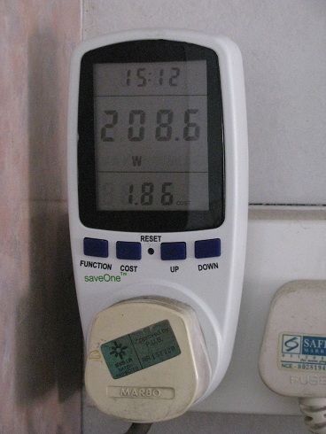
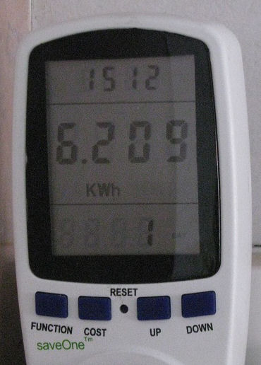


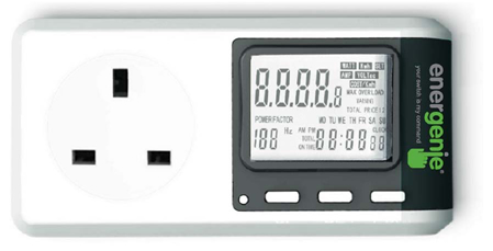

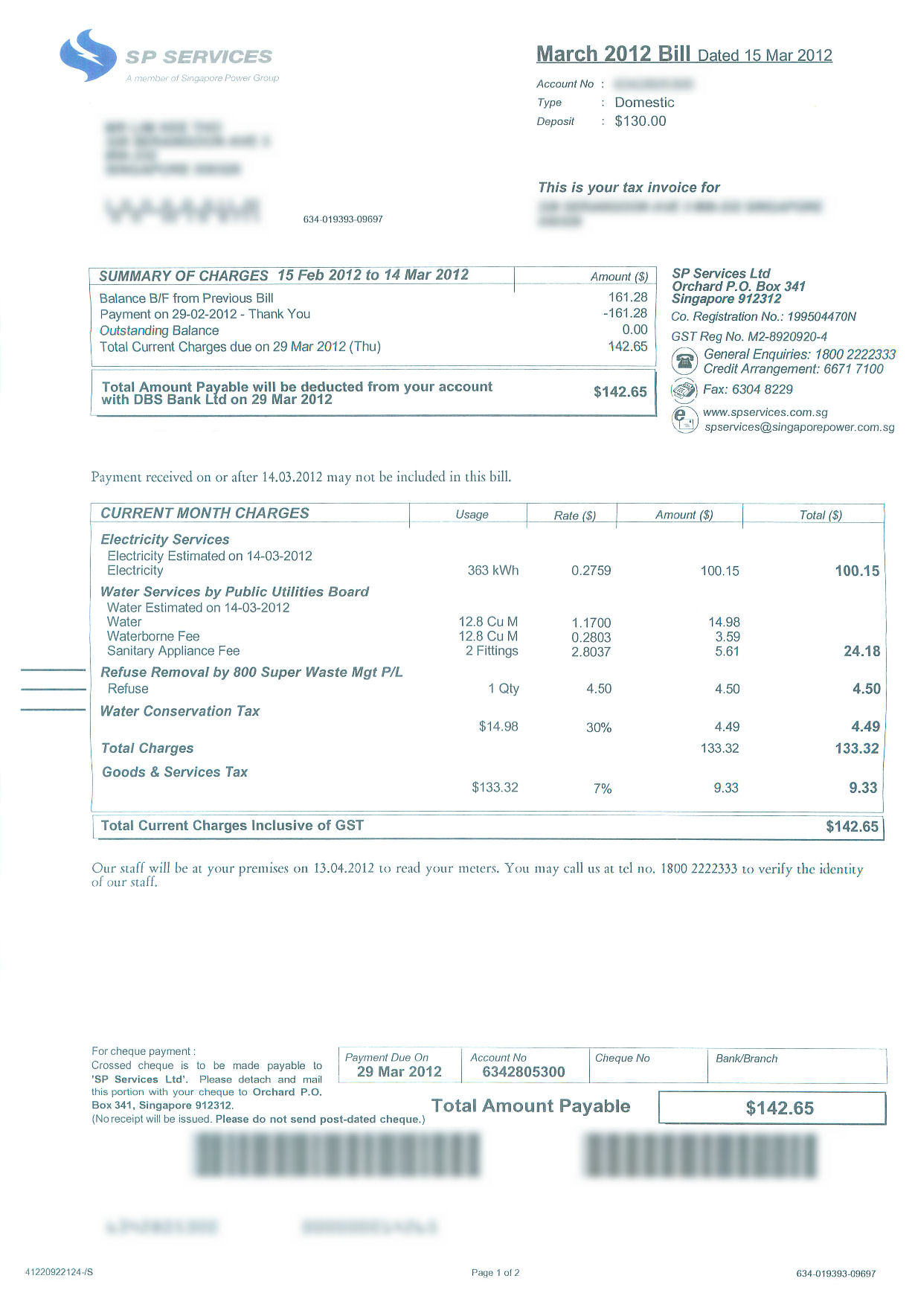


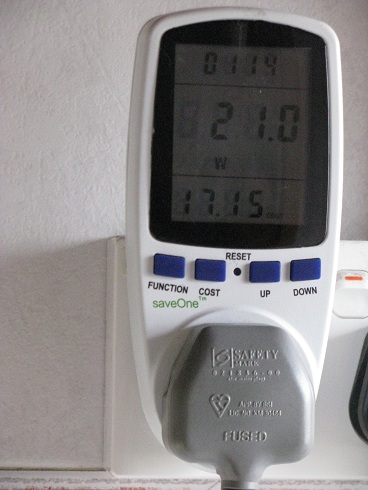
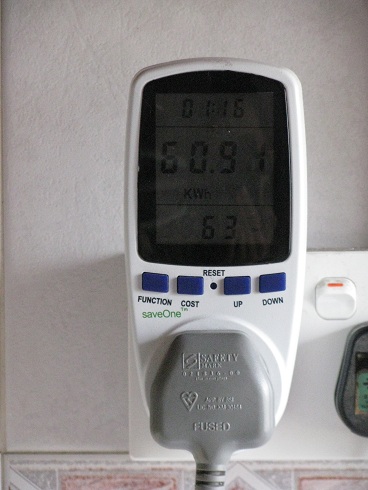

 Standby power is 1.2W
  Even if the loud door bell ring is activated, the consumption still remains at 1.2W.
  The door bell transmitter outside the door is using a battery.
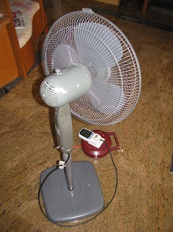

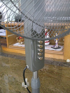
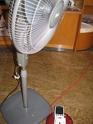

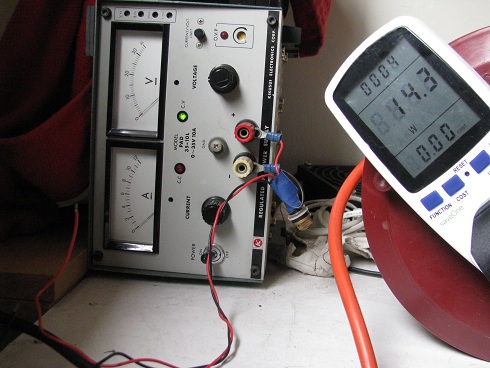
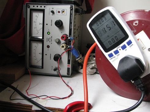
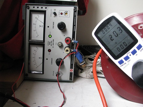
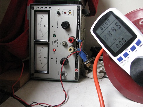
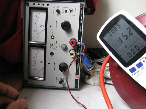

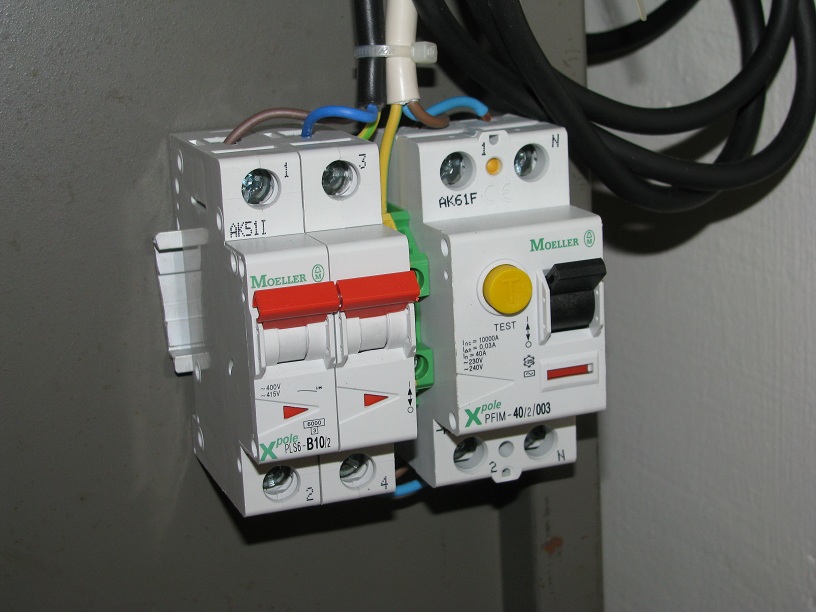
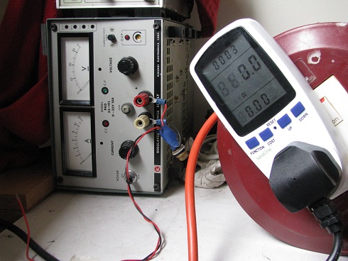
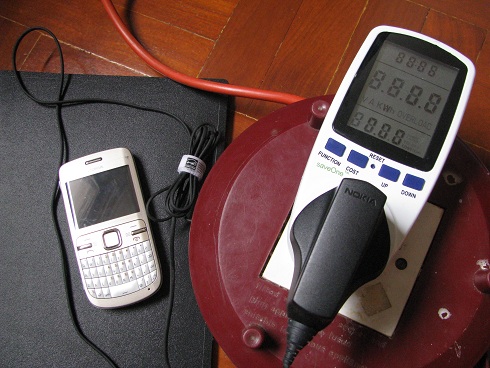
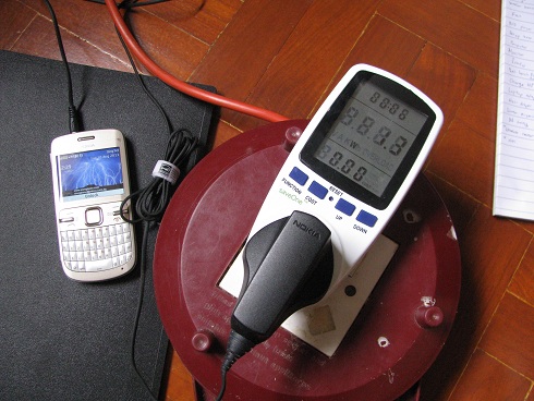


 The laptop was shutdown, and the power consumption drop back to 0.328A, 0.69PF. Should be about 45W.
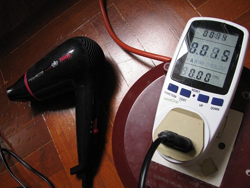
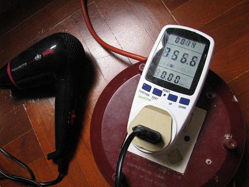


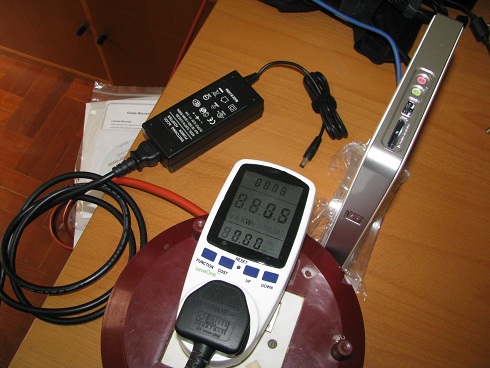


 Power consumption during standby with mini PC switched off.


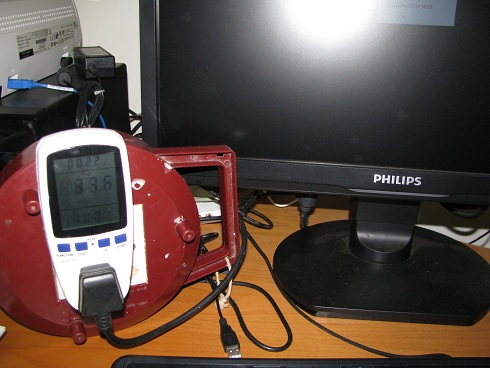

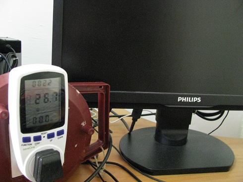
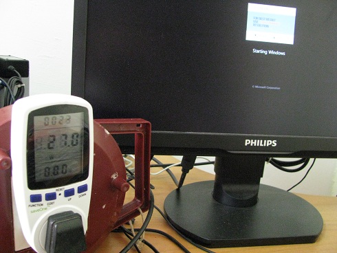


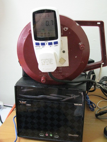
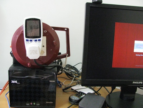


 Printer on standby 11.5W to 750W
 Printer reaching its peak 776.1W.
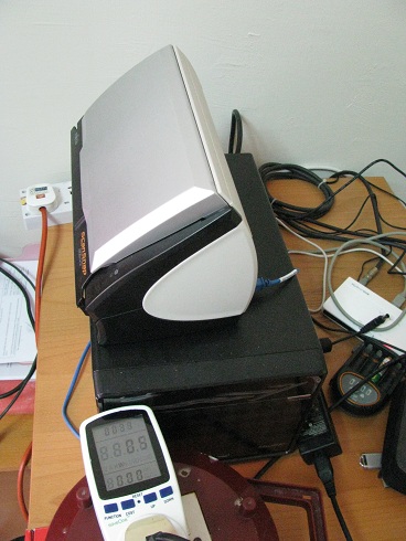
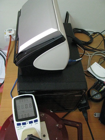
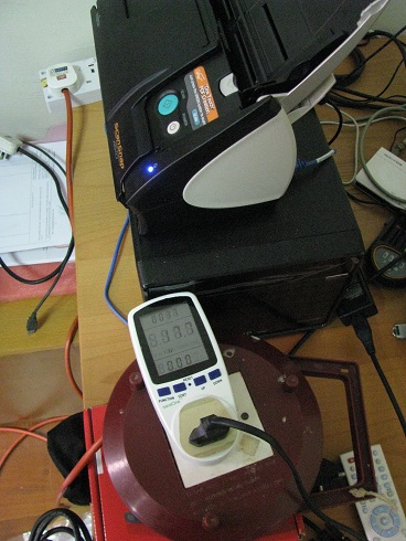


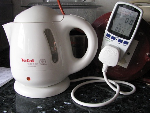


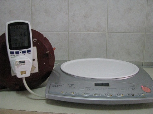

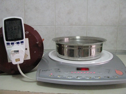
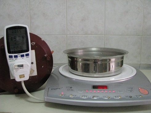

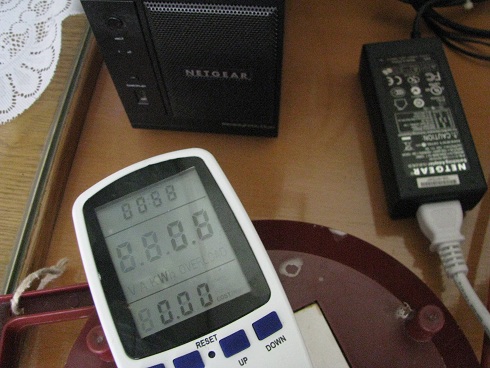
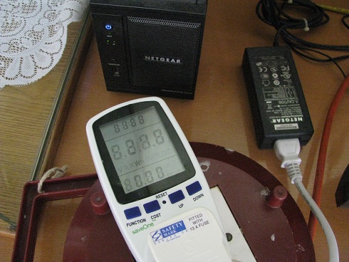
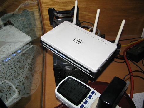
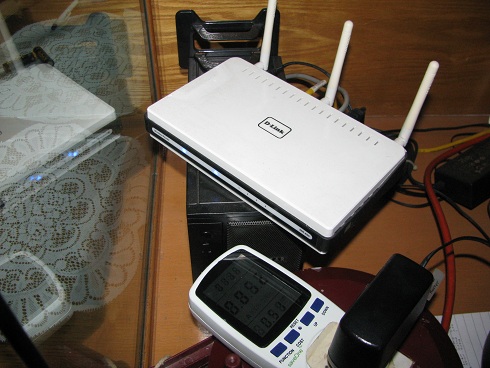

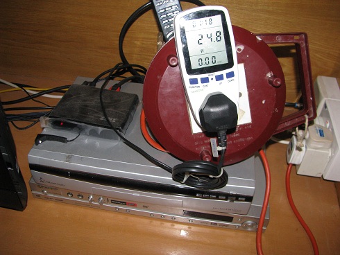

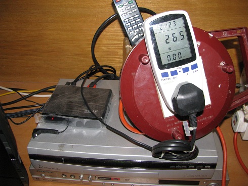
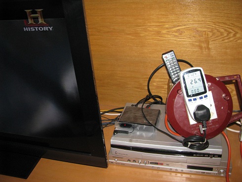


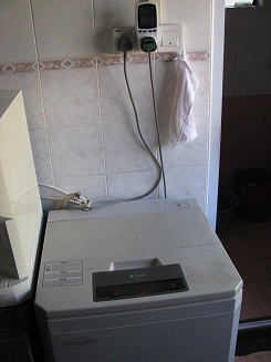

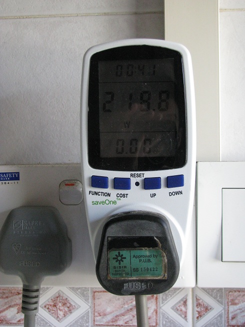
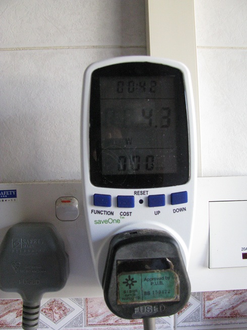

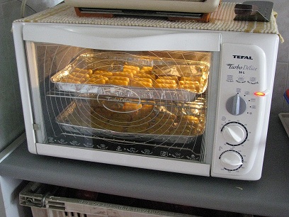


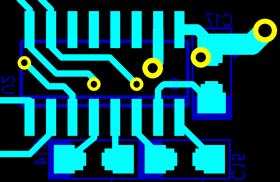

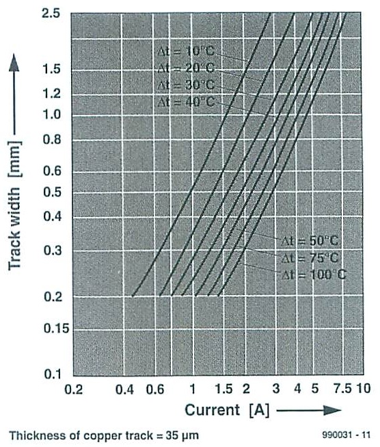
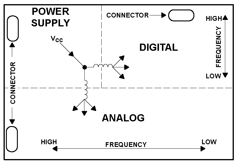
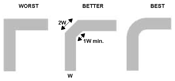
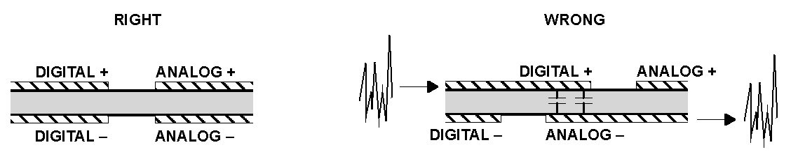


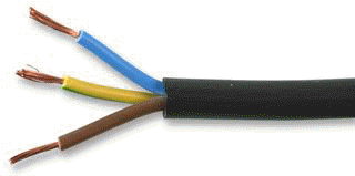 230Vac power cable 16mm2 (absolute maximum 69A)
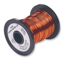
 Audio cable (shielded), Belden 8760
 Category 5E network cable, 8060-OZZ7FNL from
Alcatel
Category 5E network cable, 8060-OZZ7FNL from
Alcatel
 Multipurpose 10core shielded.
(RS232 communication, data signal), Belden 9540, Belden 9536 (6 core),
Belden 9534 (4 core)
Multipurpose 10core shielded.
(RS232 communication, data signal), Belden 9540, Belden 9536 (6 core),
Belden 9534 (4 core) Category 5E network cable
 Ribbon cable, 1.27mm
pitch
Ribbon cable, 1.27mm
pitch Wire wrapping wire, Ok Industries
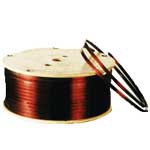 Wire copper enameled
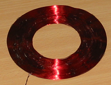
 Wire
copper enameled (very fine)
Wire
copper enameled (very fine)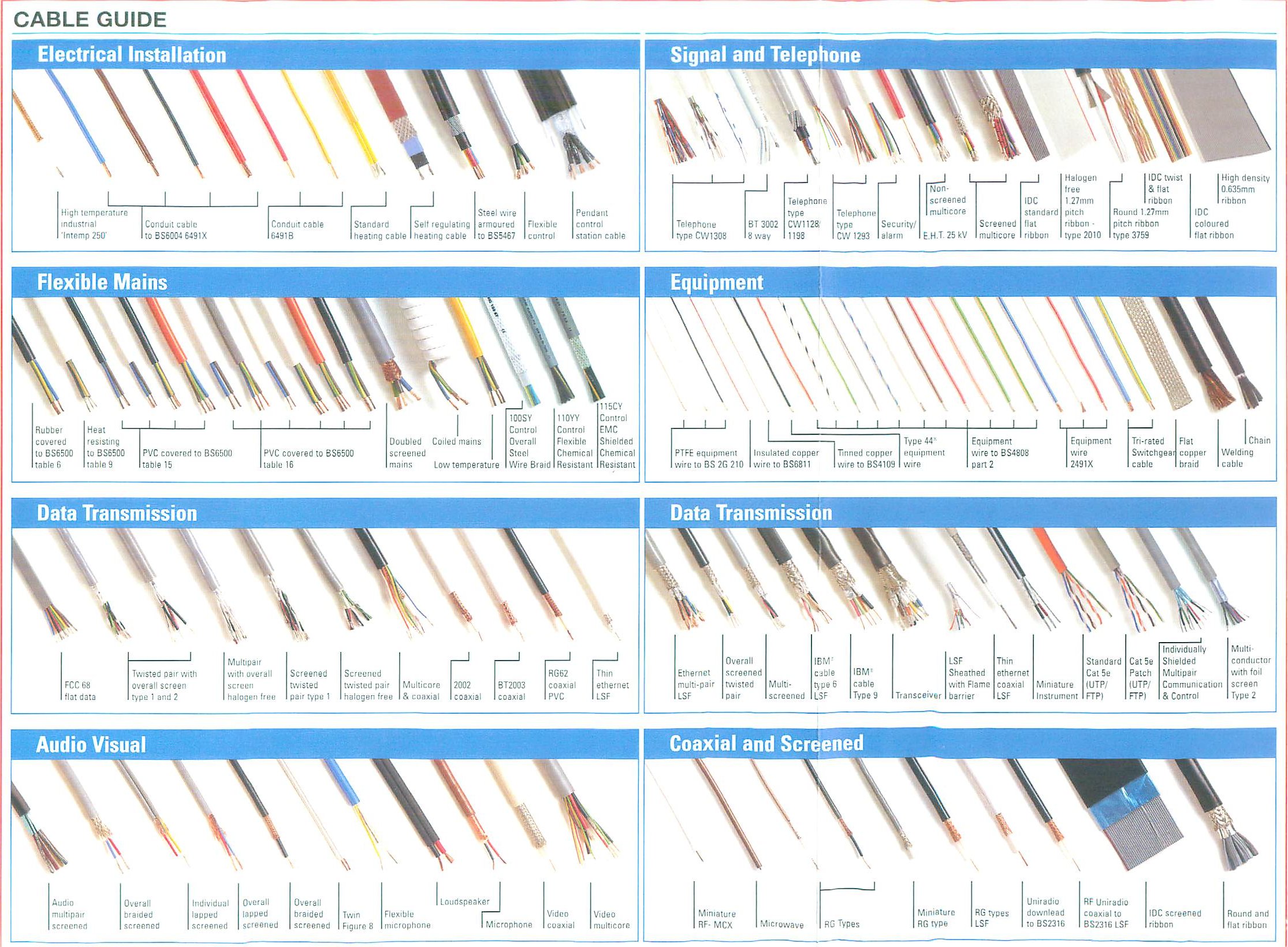
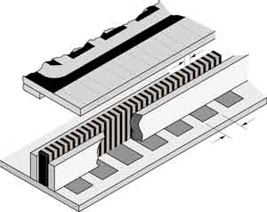
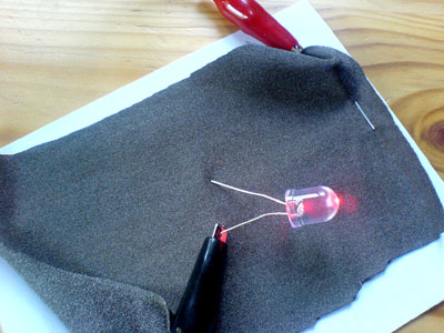 this pic is tken from other website


 Click here to access to footprint
page.
Click here to access to footprint
page.


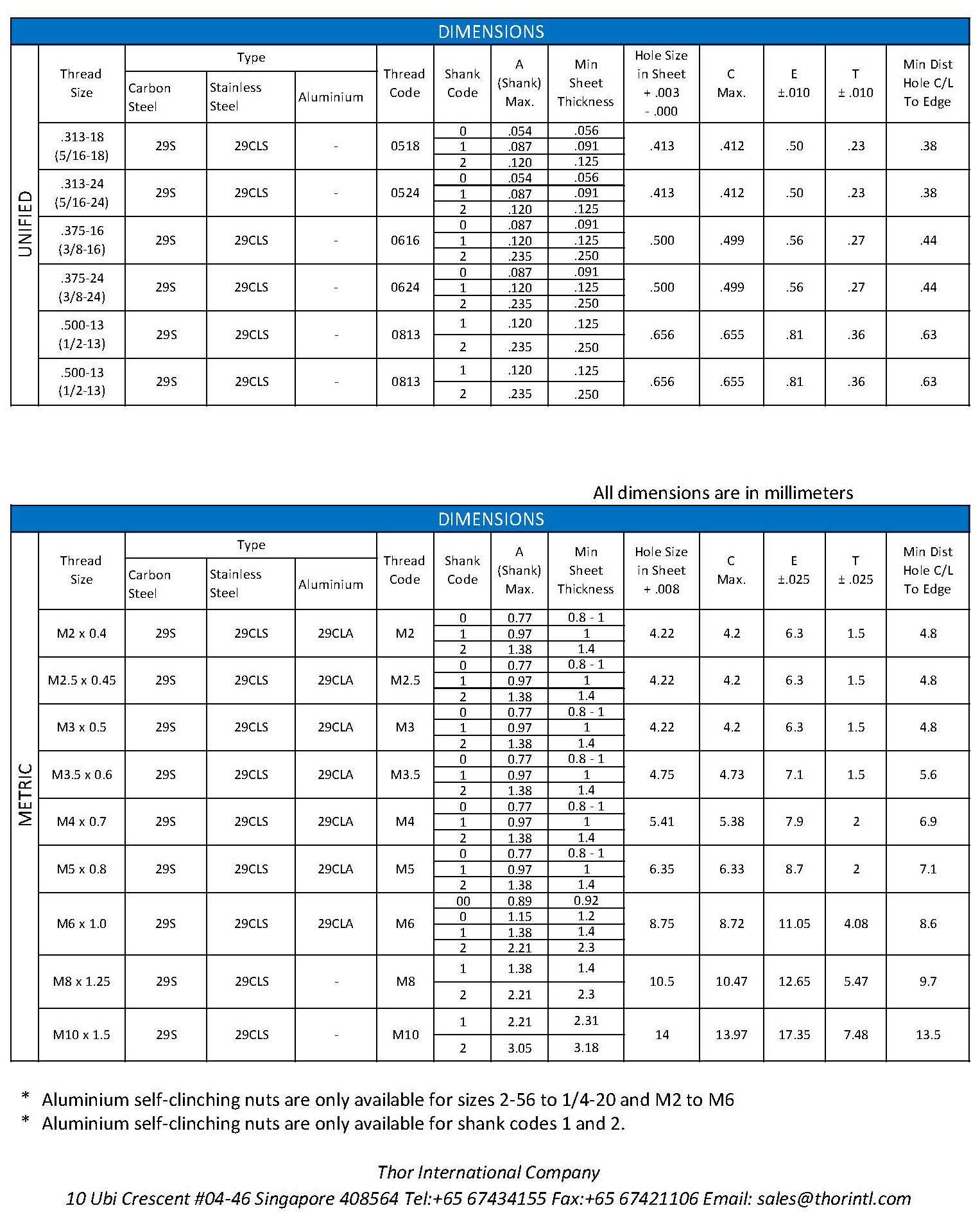

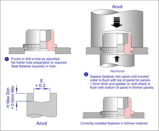


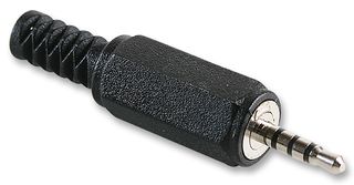

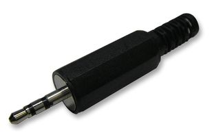


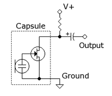


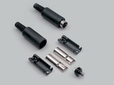
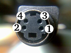
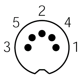

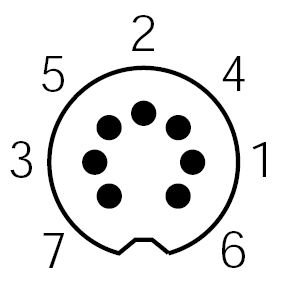
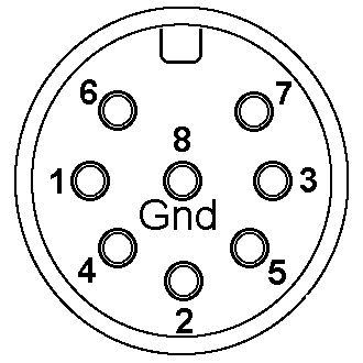
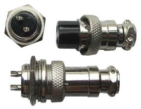
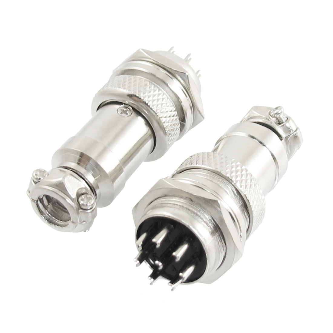
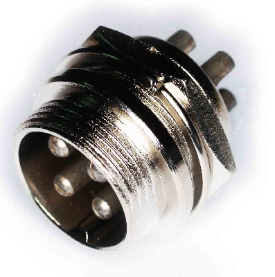


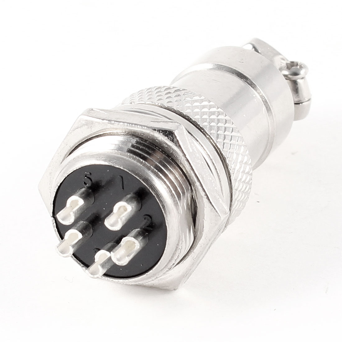


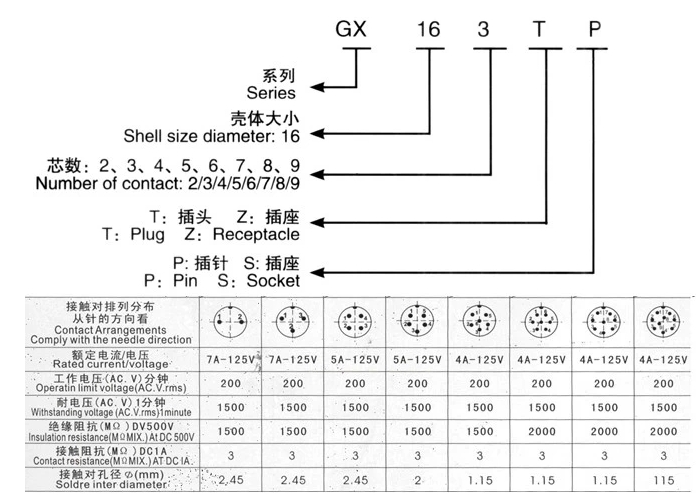

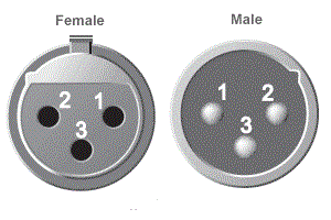
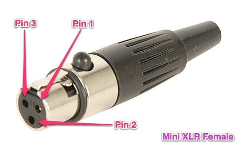
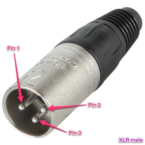
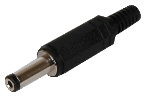
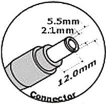
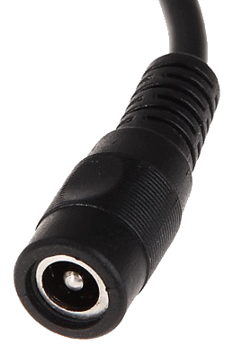


 Molex SPOX 5267 series connector header THT 2.5mm 4 way
 Molex 5263 housing crimp receptacle 2.5mm 4 way
 molex KK 6410 series
 molex KK 6471 crimp receptacle

 B3B-ZR(LF)(SN)
 S3B-ZR(LF)(SN)
 ZHR-3
ZHR-3 SZH-002T-P0.5
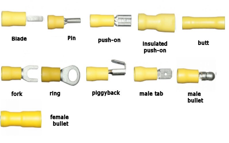

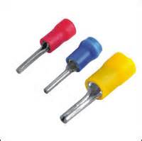
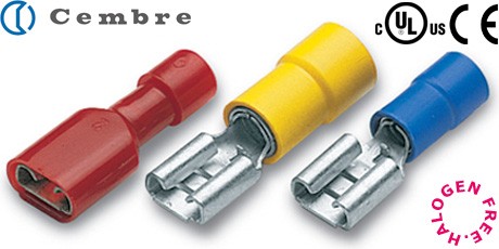
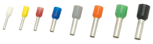


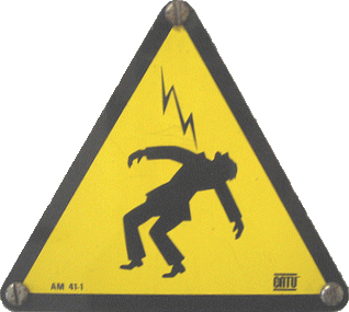


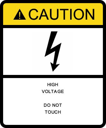


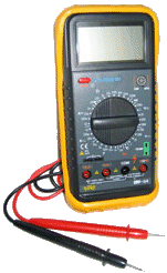 Multi-meter.
Measure between the “live” and “nuetral” line to check if 230Vac is present.
Multi-meter.
Measure between the “live” and “nuetral” line to check if 230Vac is present.
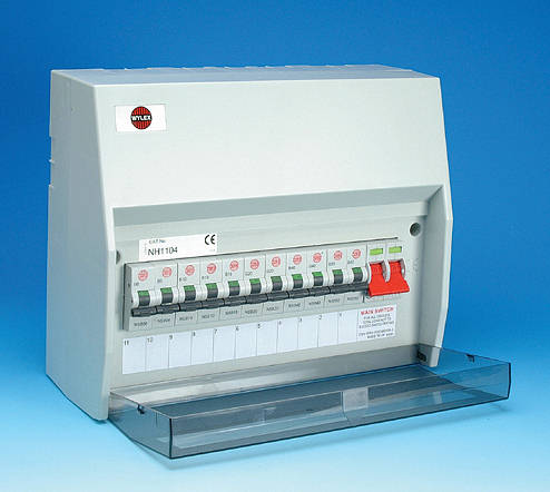
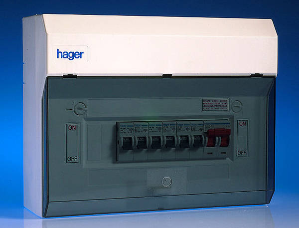


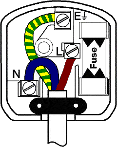 This
This


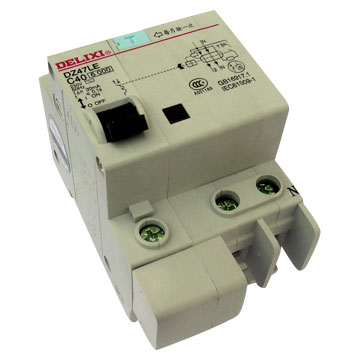


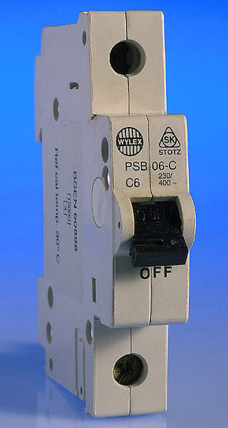


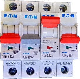


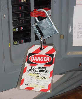


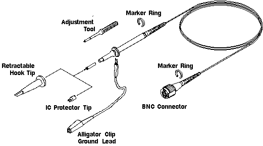

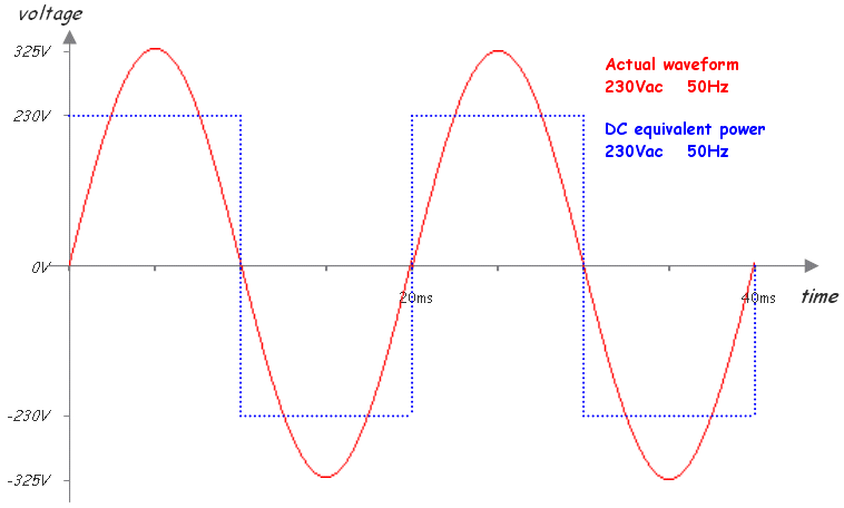
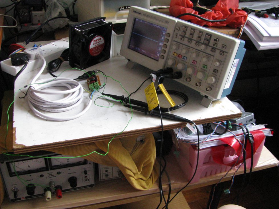

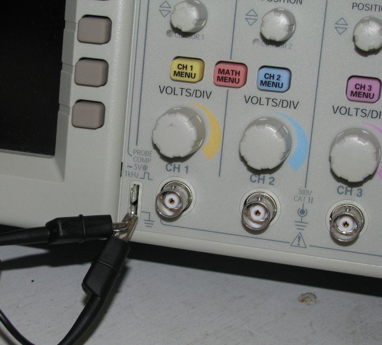
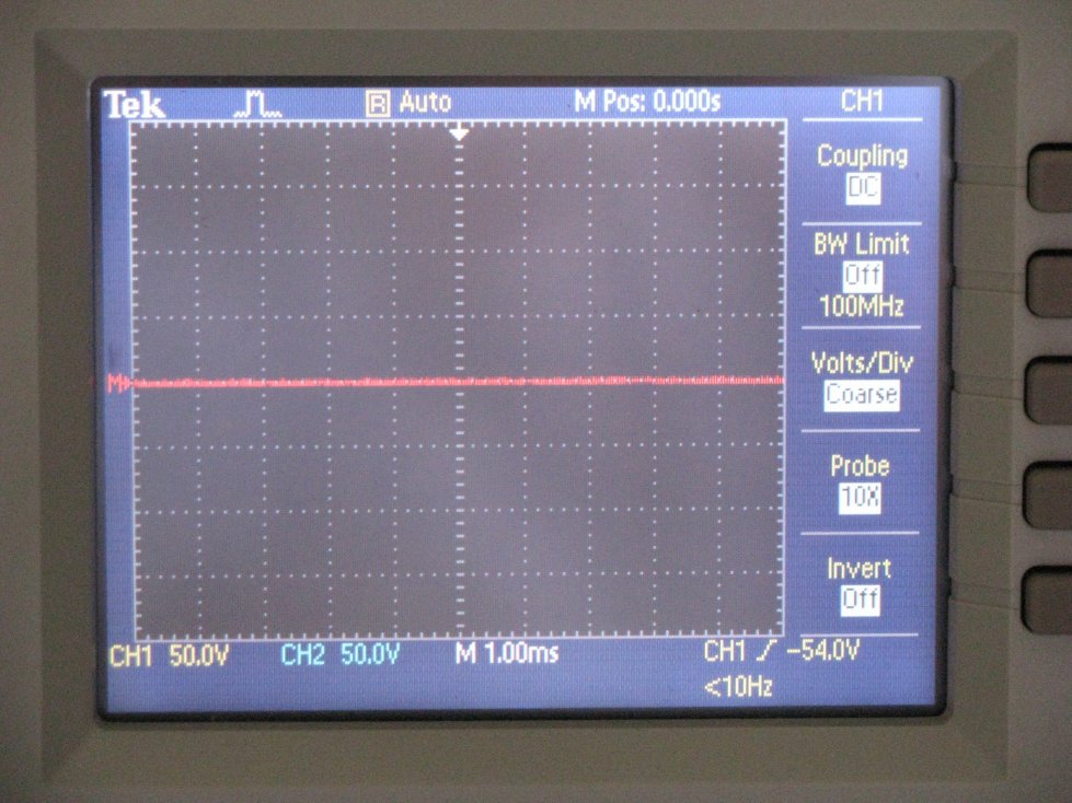


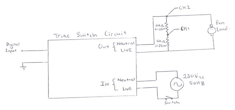


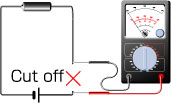

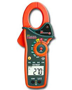
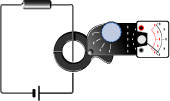
 a mini current sensor for AC power line. Comes with 1:300, 1: 500, etc… transformer coil ratio
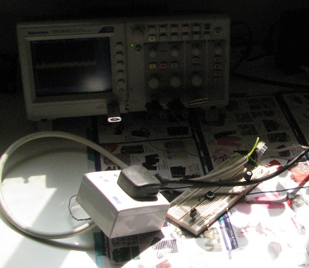
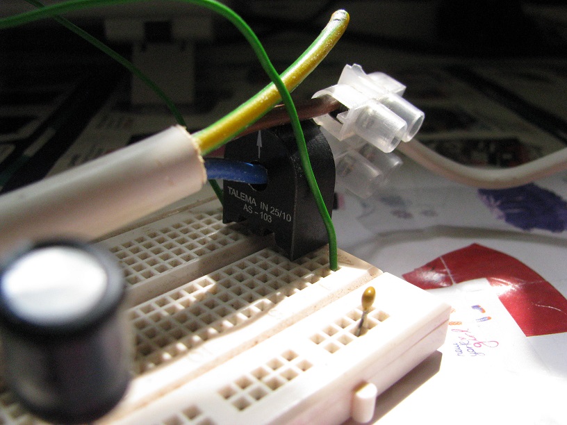
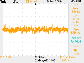
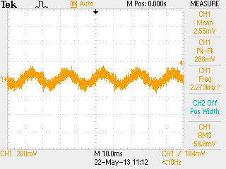
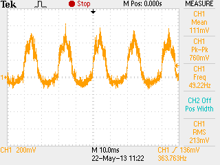
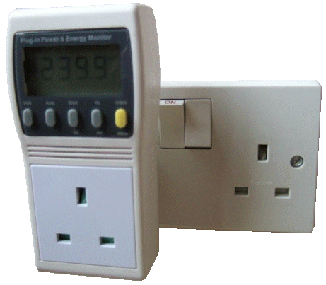


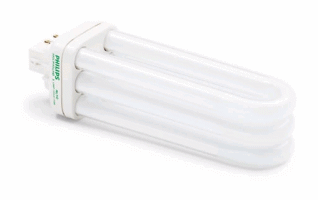 Philips
PL-T compact fluorescent bulb
Philips
PL-T compact fluorescent bulb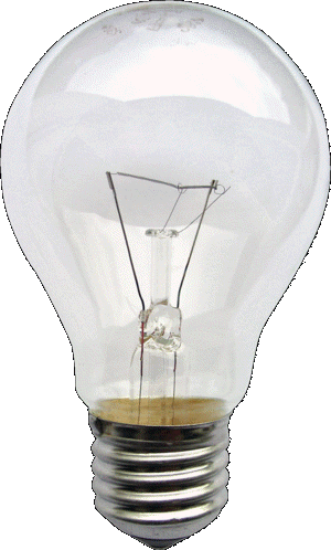 Incandescent
Light Bulb
Incandescent
Light Bulb

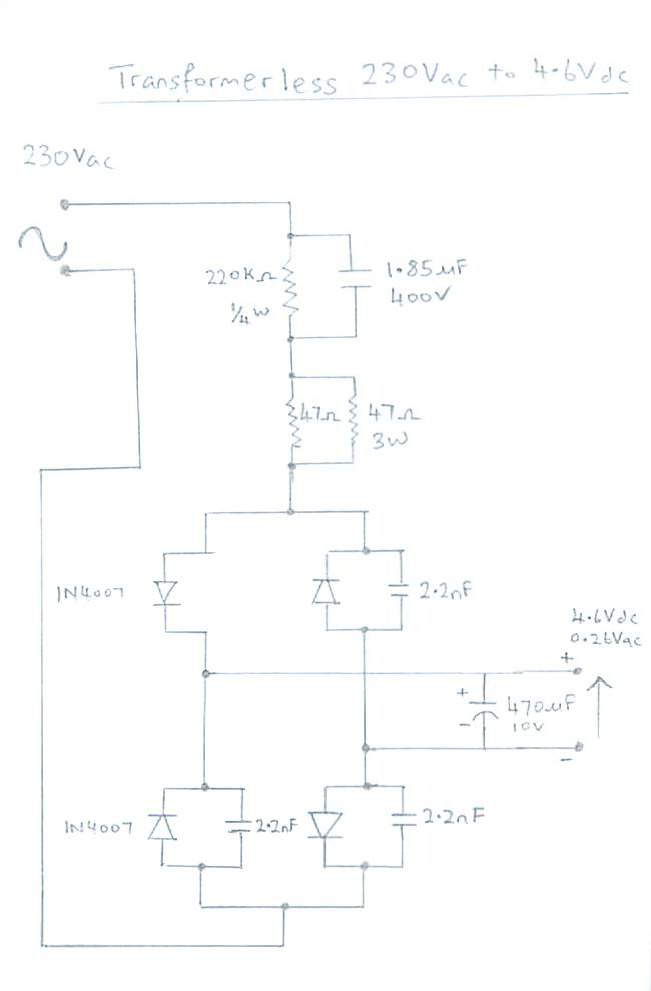

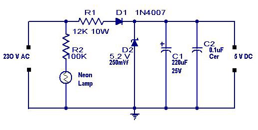


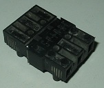
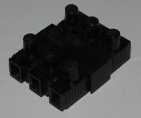
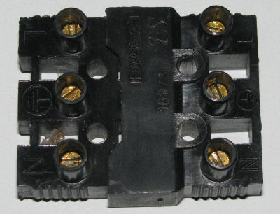
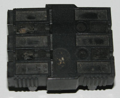
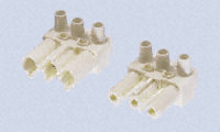
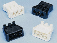


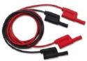


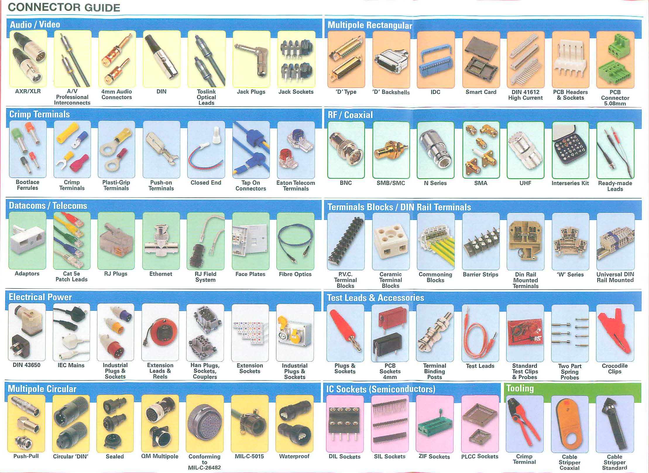
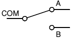

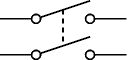
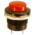
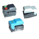
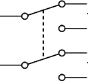
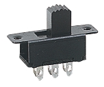


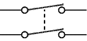
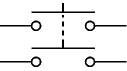
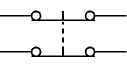

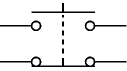
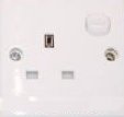


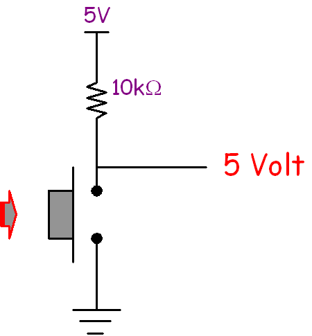
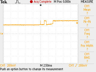

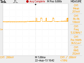
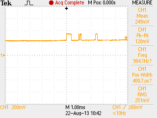


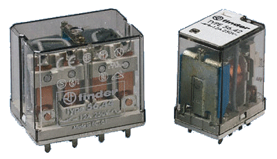
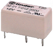
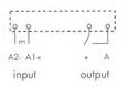
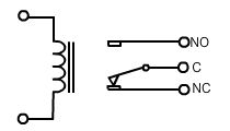
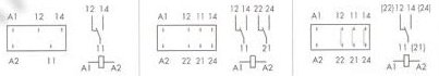
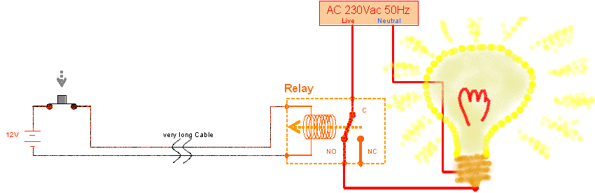
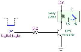


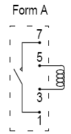

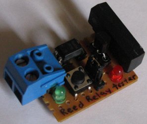

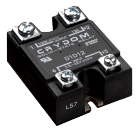

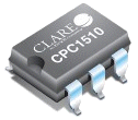
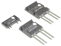
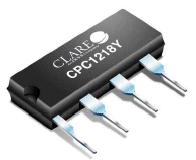


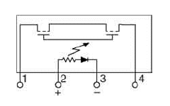

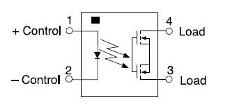

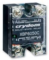
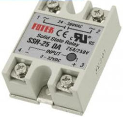

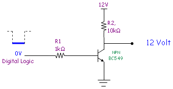
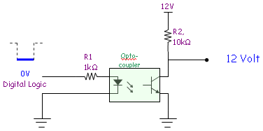
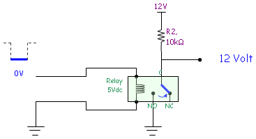
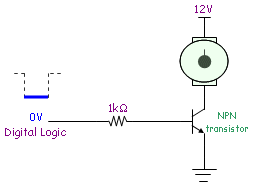

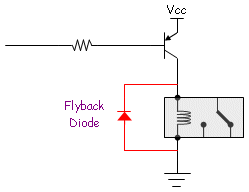
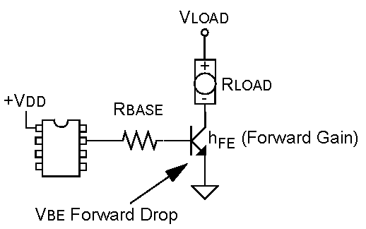


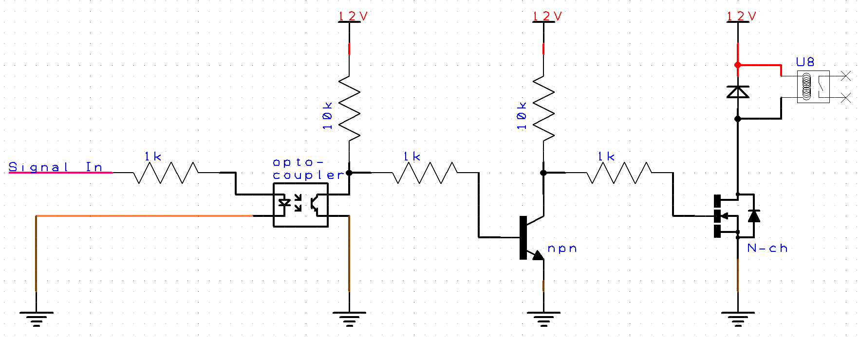
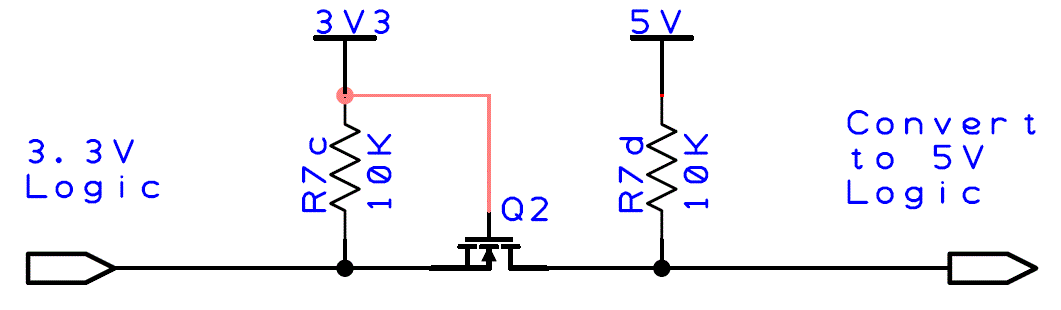
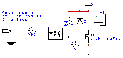


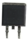

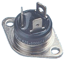

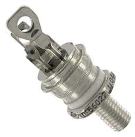
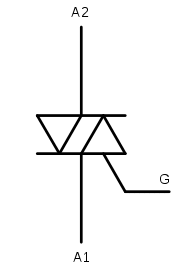
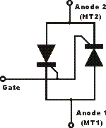 Equivalent
circuit for Triac component.
Equivalent
circuit for Triac component.
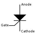
.png)
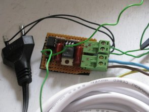
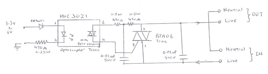


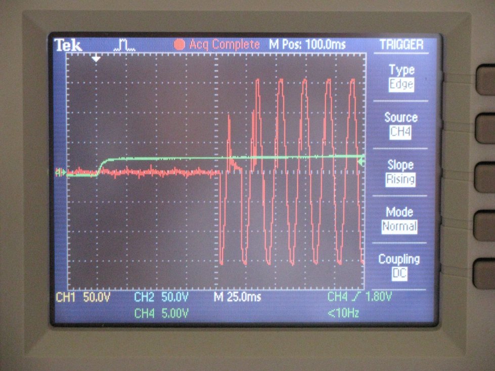
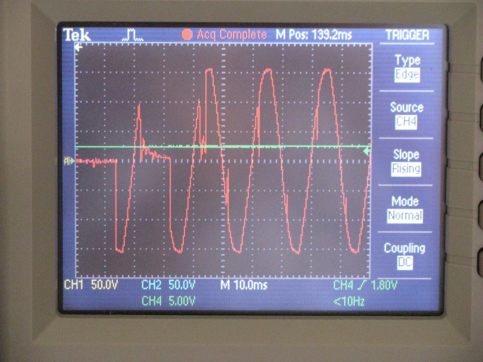
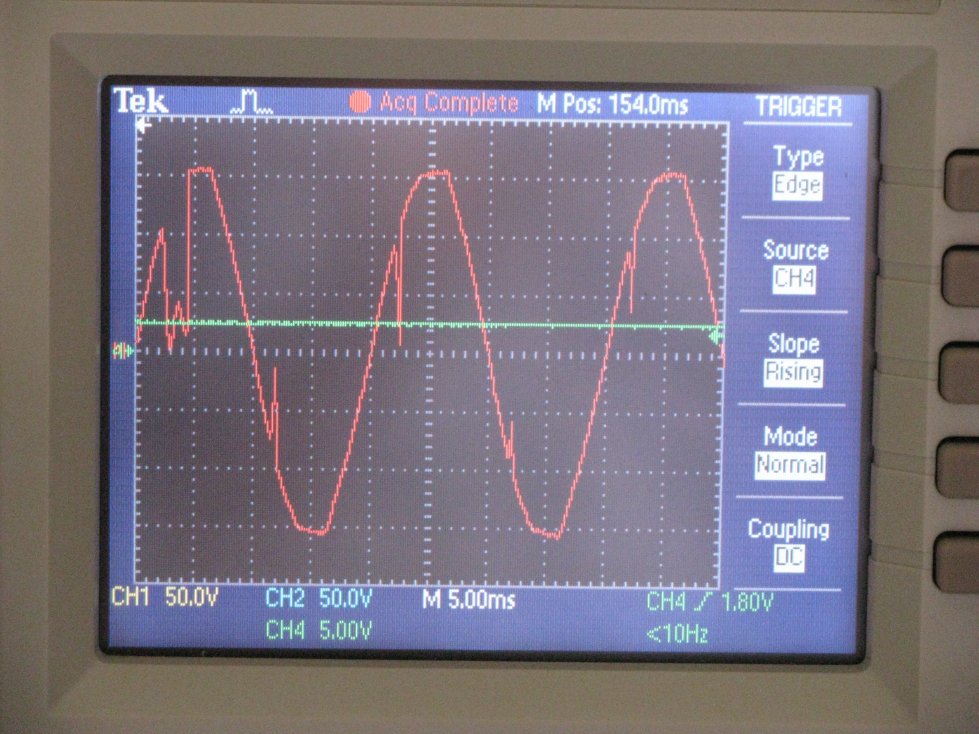

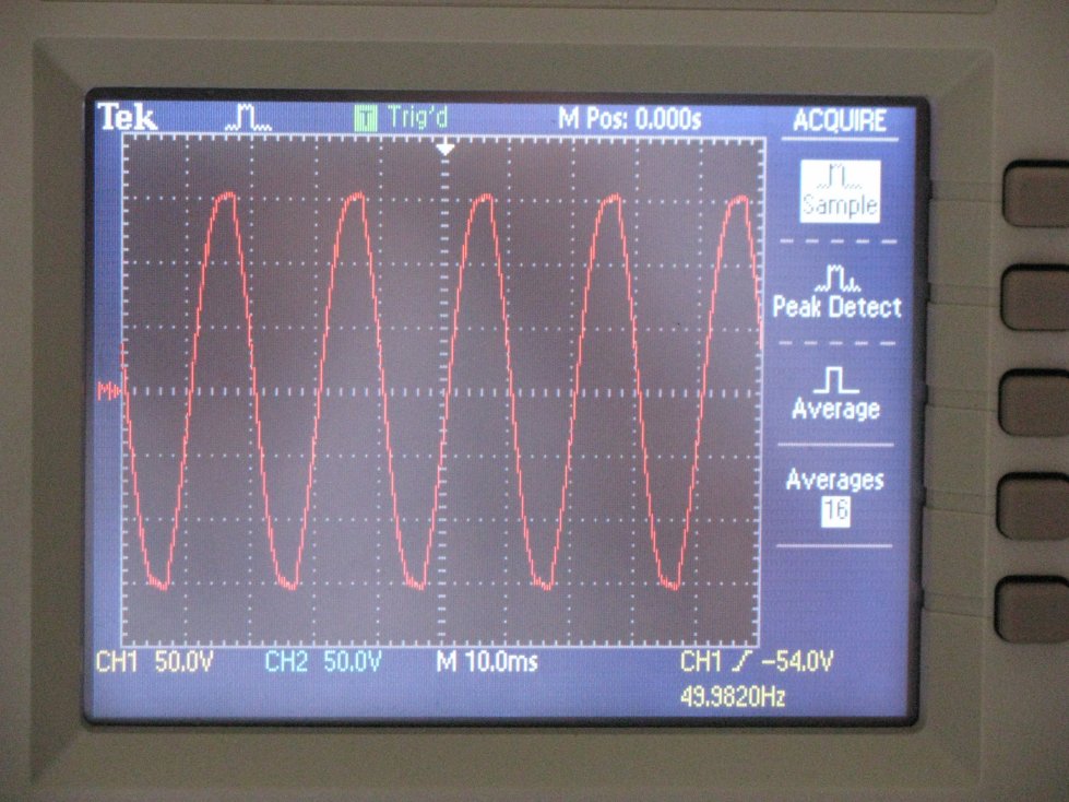
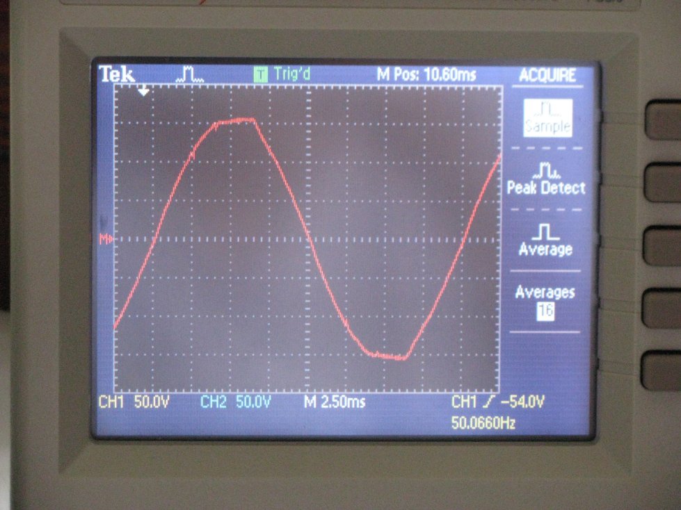
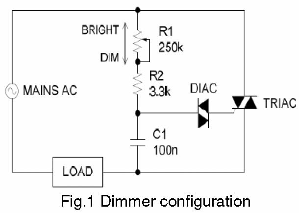
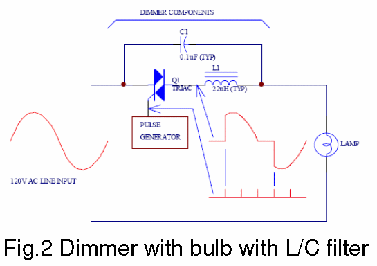
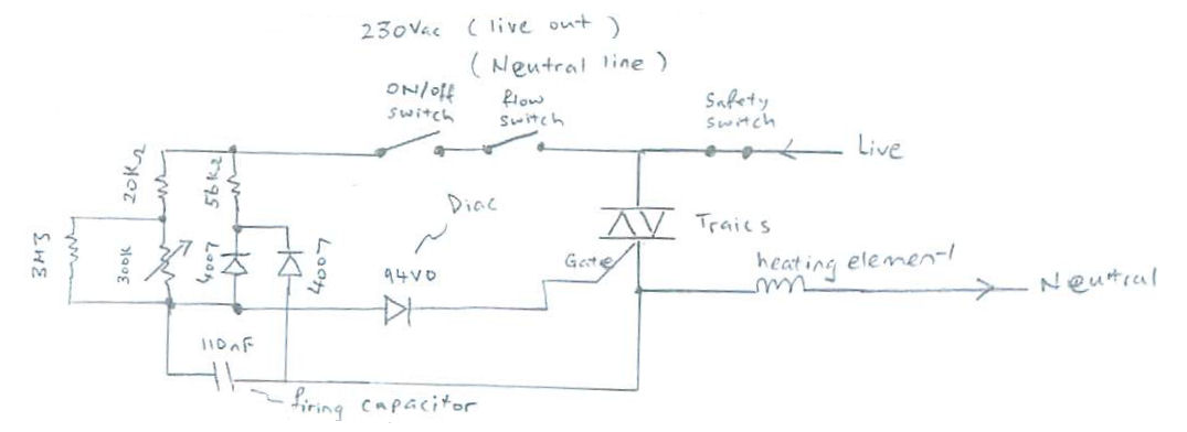

.jpg)
.jpg)
.jpg)
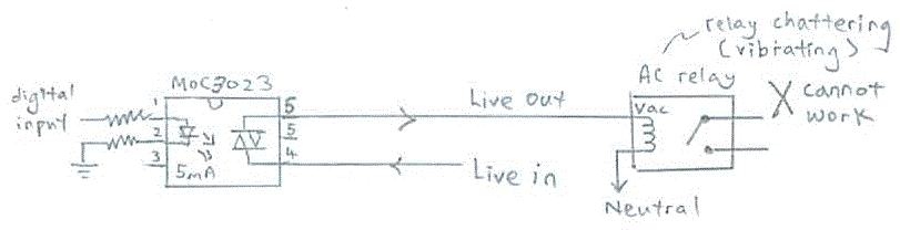
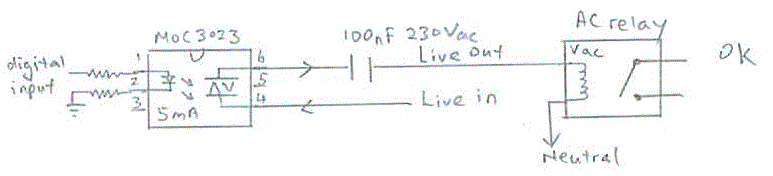
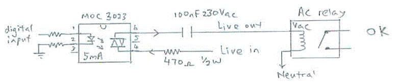
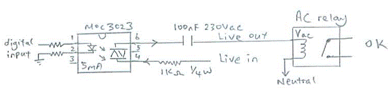

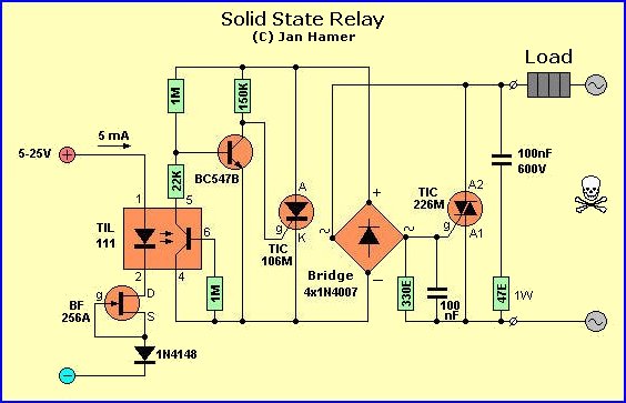
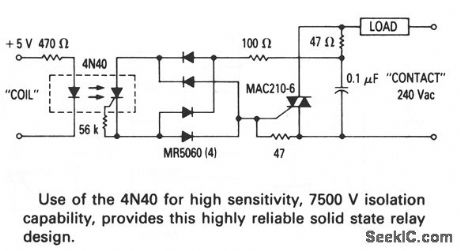
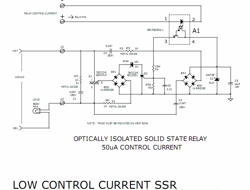


 This traffic system is
 green yellow red colored light using visual
 If you can understand the
 Sound transmission


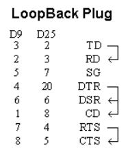
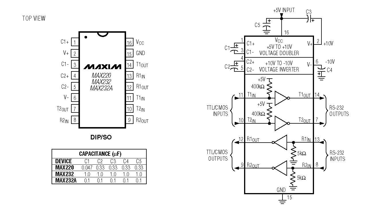
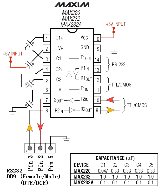


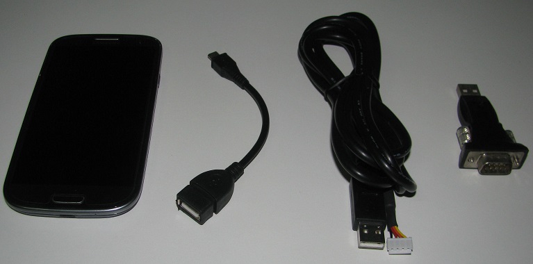
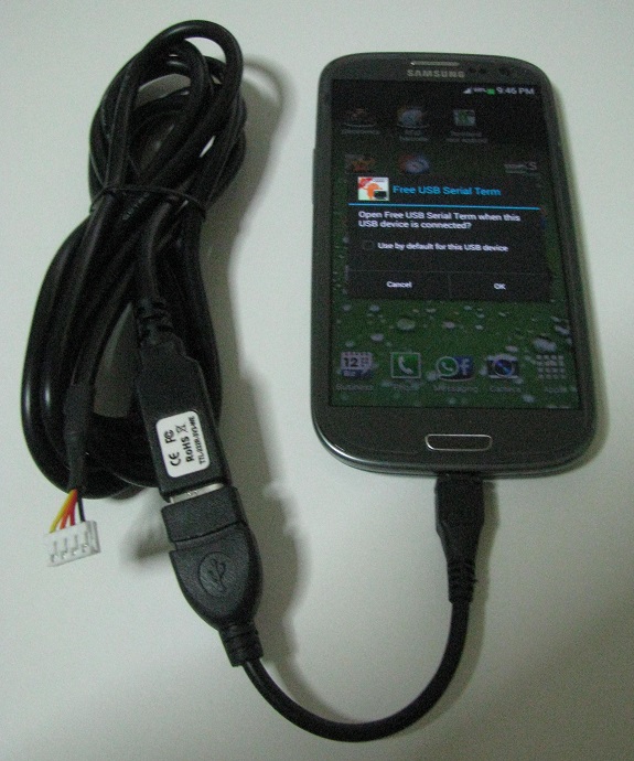

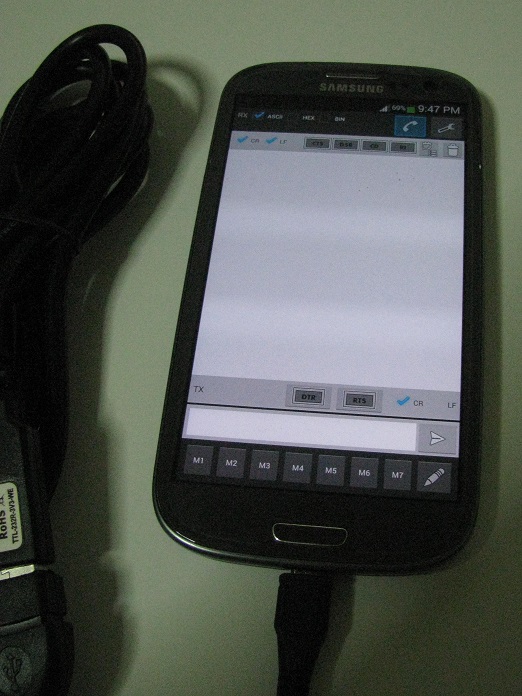

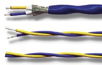
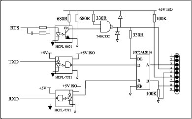


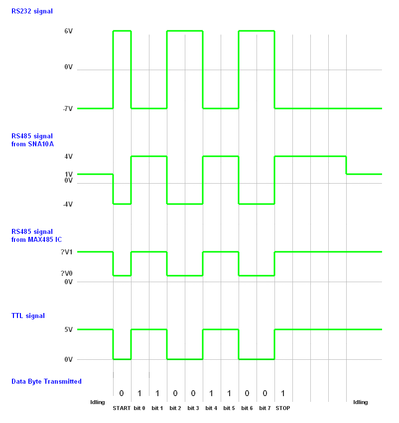


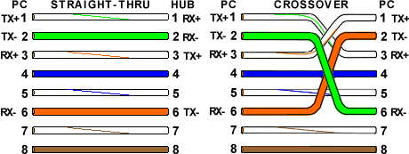
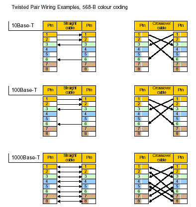
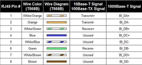

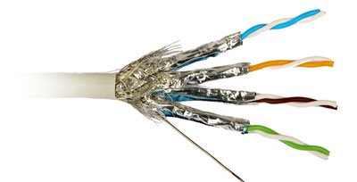


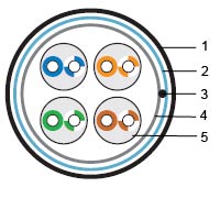
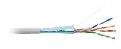


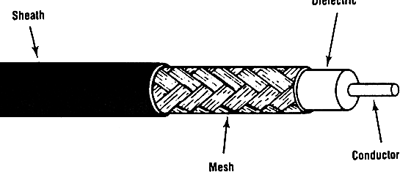 Coaxial


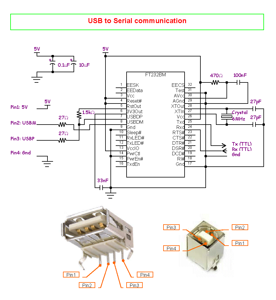
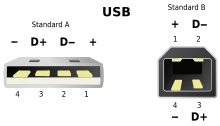
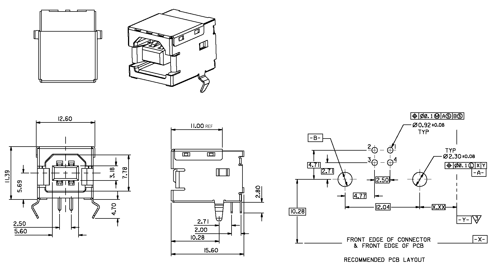


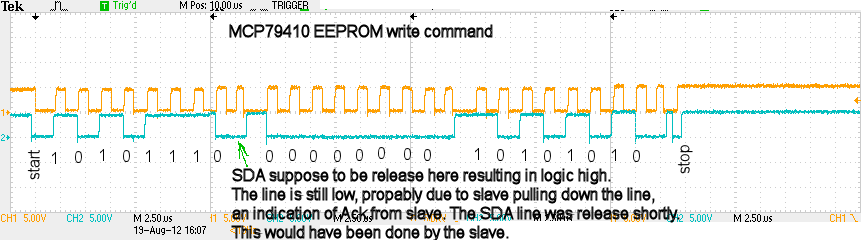

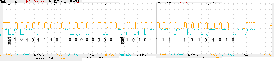
