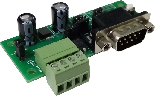
This is a pulse output board using RS232 communication. It allows your computer with an RS232 port to control an external electronic hardware through pulsing. For those computers that have an only USB port, a USB to RS232 converter can be used to allow connection to this RS232 pulse output board. You can also control this board using Raspberry Pi or other embedded computing board.
This board can be programmed with a precision pulse out timing and can also be customised with a specific algorithm to suit your application.
*** This board has been replaced by a newer version.
Please click here for more RS232 Pulse Switch OUTPUT Trigger device information. ***
Application
- Car park barrier control.
- Coin/Notes acceptor pulse trigger.
- Washing machine pulse control.
- LED strobe light control.
- Water or air valve actuator control.
- Security alarm or announcement system activation.
- Automatic sliding or swing door control.
Features
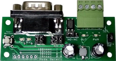
- Mode Select for pulse timing of 100msec, 50msec, 30msec, 10msec (or other custom timing through RS232).
- Quick Test Button push switch.
- OUT, Pulse output option (normally open NO, or normally close NC).
- Isolated signal pulse output or Share GND.
- PWR, Wide input voltage from 12-24Vdc (7V, 9V, 12V, 24V), max up to 100mA
- Input voltage polarity protection
- Simple labelling and LED indicators on board.
- RS232 serial COM port (baud-rate 9600bps, default/cross, TX & RX indicator)
- Special mode to measure the pulse width of a coin acceptor.
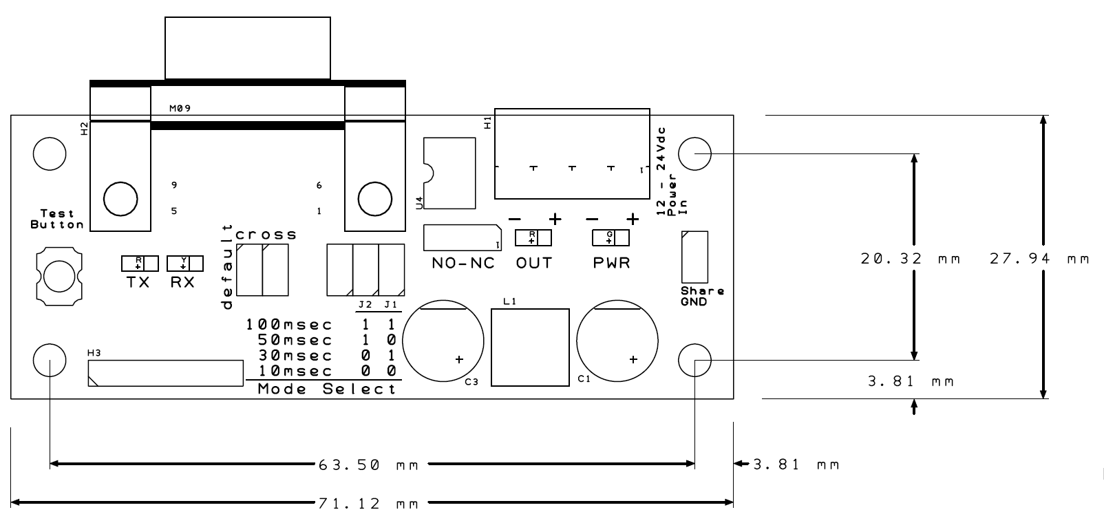
- Size approximate 71.1 x 38 x 17mm, 71.1 x 28 x 1.6mm (board size)
- Weight about 22g
Pulse OUT Timing Settings
Mode select for pulse OUT timing.
| Pulse OUT Timing | J2 | J1 |
| 100msec | ON | ON |
| 50msec | ON | OFF |
| 30msec | OFF | ON |
| 10msec | OFF | OFF |
RS232 Communication Settings
Default RS232 settings
- Baudrate 9600bps
- Data bits 8 bits
- No Parity
- 1 stop bit
- No hardware flow control
The RS232 port accepts data byte from an external controller. Any byte received will trigger a signal pulse on the output. If your equipment requires a minimum delay between the pulse, you can insert a short delay before issuing the next byte to this controller.
Issuing of two consecutive pulses will lengthen the output pulse timing. The design ensures that your controller is able to provide a variable delay between pulses as required by your equipment. It will also ensure that the controller will not be jammed with queue request.
This RS232 pulse board will echo back the same byte that is sent via the RS232. This indicates that the emulator is connected to your system. If you send a byte and did not receive any byte, it may mean that there is a connection problem or some issues on the board.
Pressing the “Test Button” on the board will return a byte “0x01” back to your system. Releasing the button will return a byte “0x00”.
RS232 Socket DB9 (male) Pinout
The RS232 communication requires only 3 pins. The TX signal (data transmit), the RX signal (data receive) and the signal ground. The rest of the pins are not in use because this RS232 uses asynchronous communication.
RS232 Socket Pinout
- Pin 1 – nil
- Pin 2 – Rx
- Pin 3 – Tx
- Pin 4 – nil
- Pin 5 – Ground
- Pin 6 – nil
- Pin 7 – nil
- Pin 8 – nil
- Pin 9 – nil
If the RS232 cable is not a cross-cable, jumpers are available on the board to allow for RS232 data communication.
Pulse Width Measurement for Coin Acceptor
A typical coin acceptor usually emits a pulse to indicate that a coin is accepted by the coin acceptor. The signal output is usually a pulse of 20ms, 50ms to 100ms. While most of the coin acceptor works the same, some are not. Some coin acceptor emits special pulses to prevent people from hacking and cheating the coin vending system.
This pulsing type of coin acceptor interface is not standardised within the coin payment industry. Wrong setting on the coin acceptor may cause an inconsistent result to the interfacing system. It is important to measure the pulse width emitted by the existing coin acceptor device before using this RS232 trigger board to emulate it.
This RS232 trigger board has a special mode to allow you to measure the pulse width emitted by your current coin acceptor. This will ensure that you are able to emulate your coin acceptor with precision.
Board Dimension
Custom Pulse Out RS232 Board
Custom and programmable electronic RS232 board to suit your application.
Contact us today to customised a pulse output RS232 board for your application today.
*** This board has been replaced by a newer version.
Please click here for more RS232 Pulse Switch OUTPUT Trigger device information. ***