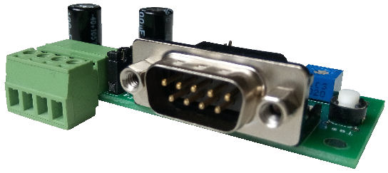
This electronic board enables your computer or embedded device (RaspberryPi, Beagle Board) to trigger a switch contact (dry contact) which can trigger another external electronic system.
The board is simulating a physical switch which allows you to program from your computer and control another system via the RS232 communication port.
Application
- Use for activating another system which can be controlled by a push button switch.
- Trigger car barrier system.
- Simulate a push button pressed.
- Programmed for coin acceptor used.
Features
- Pulse output control via a computer RS232 communication
- Power input 9Vdc, 12Vdc up to 24Vdc. Alternating voltage range from 9-24Vac is acceptable.
- The output is a dry contact switch (output rating up to 24Vdc, 0.5A)
- Quick push test button to manual trigger pulse output.
- Precise pulse width control up to 1msec resolution.
- The pulse width can be controlled dynamically via RS232 command.
- Pulse width settings can be retained when is power off.
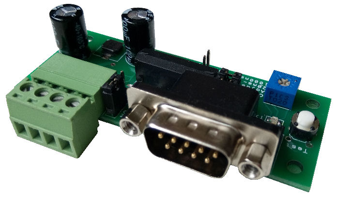
Connectors
The board has two connectors. A DB9 connector is on the board for RS232 communication. You can refer to the pinout section for RS232 connection information. The other connector is a 4 ways screw terminal connector.
Pin 1, 2 of the screw terminal connector features the power input for this board. The board can accept voltage input from 9Vdc, 12Vdc to 24Vdc. It can also accept 9-24Vac (alternating voltage). The power consumption of the board is very low. By default, pin 1 is +ve, and pin 2 is 0V. Connecting the power input in the wrong polarity will not cause any damage to this module.
Pin 3, 4 of the screw terminal connectors the pulse output. The output is a dry contact output. By default, it is normally-opened (NO), and will be shorted when pulsed. There is a jumper next to pin 4 which allows you to choose a normally-closed output (NC).
Settings for Pulse Output
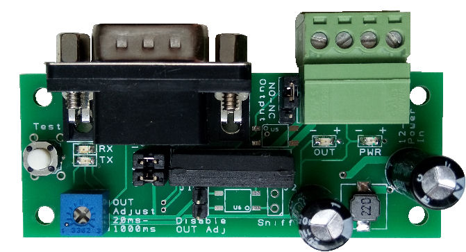
On the left side of the board, there is a push button switch. This is a quick manual test switch. Pushing this switch will trigger the pulse output. The “OUT” indicator will be activated for the pulse width duration. At the same time, a byte (0x01) will be sent out via the RS232 port to notify the computer when this button is pressed. When this button is released, a byte (0x00) will be sent out.
The blue colour trimmer “OUT Adj POT” is for manual adjustment of the pulse width of the OUT. The timing can be set from 20 msec – 1000 msec (to be exact, from 10msec to 1220 msec). Turn the POT clockwise to increase the pulse width timing. Remove jumper J1 to set the pulse width timing from “OUT Adj POT”.
Power Up Test of the RS232 Circuit Board
When you first power up the board with jumper J1 attached, pressing on the push button on the left will trigger the OUT port near the green connector. You will notice that the OUT indicator will pulse a red light for 400ms. This is the default pulse width set in the “Chip Memory”.
Next, remove the jumper J1 from the header. Press the push button. You will notice that the OUT indicator light pulse a red light with a different timing. Adjust the OUT trimmer fully anti-clockwise, and press the trigger button again. You will notice a very quick pulse of 10 msec (minimum pulse width). Adjust the OUT trimmer fully clockwise, and press the push button again. This time, you should notice the OUT output pulse length of about 1220 msec.
The setting from the chip memory can be configured via the RS232.
Communication RS232
Default RS232 settings
- Baudrate 9600bps
- Data bits 8 bits
- No Parity
- 1 stop bit
- No hardware flow control
Upon power up this board, a message will be reported via this RS232 port. The report will display the pulse width timing data as represented by the trimmer POT hardware setting and also the pulse width setting in the chip’s memory. The last line displays the actual pulse width selected. The board will select where the pulse width setting base on the jumper J1. This report can also be printed using the command 0x1B
Example of setting report if J1 is removed or when the data of the “Chip Memory” is set to 0x0000 :
RS232 Pulse OUT Trigger Operating Mode. (dated: Jun 19 2018)
[#] OUT Adj POT = 0x000A [0010 msec]
[ ] Chip Memory = 0x0000 [0000 msec]
Pulse Width = 0x000A [0010 msec] (set from POT Adj)
Example of setting report if J1 is attached :
RS232 Pulse OUT Trigger Operating Mode. (dated: Jun 19 2018)
[ ] OUT Adj POT = 0x000A [0010 msec]
[#] Chip Memory = 0x0190 [0400 msec]
Pulse Width = 0x0190 [0400 msec] (set from Chip Memory)
Either the “OUT Adj POT” or the “Chip Memory” data setting will be used for the actual output pulse width timing.
The default setting in the “Chip Memory” is 400msec. Assume that the POT is adjusted to the minimum (10msec).
When the jumper J1 is attached to the header, the board will select the pulse width setting from the “Chip Memory”. This means that the actual pulse width is 400msec.
When the jumper J1 is removed, the board will take the pulse width from the “OUT Adj POT”.
If the setting on the “Chip Memory” is set to 0x0000, the pulse width will be taken from the “OUT Adj POT” instead.
| Jumper J1 | Chip Memory Data | Select Pulse Width from |
| OFF | any data | “OUT Adj POT” |
| ON | 0x0000 | “OUT Adj POT” |
| ON | any data | “Chip Memory” |
Available commands to control this board
Except for the trigger command, all commands start of the byte ‘0x03‘ and ends with 2x bytes ‘0x0D‘ ‘0x0A‘. The pulse width timing is set using 4digit hex number and NOT decimal number. For example, the 4 digits hex number for 100msec is “0064“.
- To trigger the output with a pulse from computer
send byte -> ‘0xAA‘ - To trigger the output permanently active (relay on, output shorted)
send byte (ASCII character ‘1’) -> ‘0x31’ - To trigger the output permanently inactive (relay off, output opened)
send byte (ASCII character ‘0’) -> ‘0x30’ - To print out settings report from computer
send byte -> ‘0x1B’ - To set pulse width of 40ms (or 0x0028) without saving to memory (command string “P0028“)
send 8 bytes -> ‘0x03‘, ‘0x50‘, ‘0x30‘, ‘0x30‘, ‘0x32‘, ‘0x38‘, ‘0x0D‘, ‘0x0A‘ - To set pulse width of 400ms (or 0x0190) saving to memory (command string “S0190“)
send 8 bytes -> ‘0x03‘, ‘0x53‘, ‘0x30‘, ‘0x31‘, ‘0x39‘, ‘0x30‘, ‘0x0D‘, ‘0x0A‘ - To configure board to have the pulse width set by the “OUT Adj POT” (command string “S0000“)
send 8 bytes -> ‘0x03‘, ‘0x53‘, ‘0x30‘, ‘0x30‘, ‘0x30‘, ‘0x30‘, ‘0x0D‘, ‘0x0A‘
From the example, you can see that the command has two type, the ‘P’ and the ‘S’. Both are similar, except that for command ‘S’, the data are stored in the chip is non-volitile. Pulse width data stored using the ‘S’ command will be retent even after power is removed from the board. Use command ‘S’ to set a default pulse width.
Command ‘P’ should be used if you need a dynamic pulse width. The pulse width set using ‘P’ will still remain as long as the power remains connected. After a power down, the pulse width set using the command ‘P’ will be lost. Use command ‘P’ if a frequent change of pulse width is required.
RS232 Socket DB9 (male) Pinout
The RS232 communication requires only 3 pins. The TX signal (data transmit), the RX signal (data receive) and the signal ground. The rest of the pins are not in use because this RS232 uses asynchronous communication.
Default RS232 Socket Pinout
- Pin 2 – Rx
- Pin 3 – Tx
- Pin 5 – Ground
- The rest is not connected.
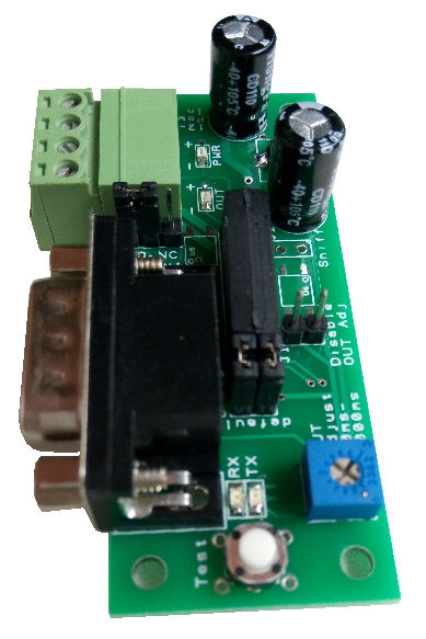
If the RS232 cable is not a cross-cable, jumpers are available on the board to allow for RS232 data communication. The jumper enables you to swap the pins for Rx and Tx from the default of Pin 2 Pin 3, to Pin 3 Pin 2 (when the jumpers are set to cross, Pin 2 – Tx, Pin 3 – Rx).
Set the jumpers to “CROSS” when you are connecting this board’s RS232 to a computer’s RS232 port. For most other devices, you should set the jumper to “DIRECT“.
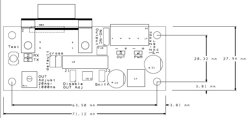
Board Dimension
Custom Pulse Out RS232 Board
Custom and programmable electronic RS232 board to suit your application.
Contact us today to customised a pulse output RS232 board for your application today.
Other forms of communication interface are also possible.