Prototyping boards allows electronic components to be manually soldered and secure neatly onto a board platform. Compare to plugging the electronics component onto a temporary breadboard, a prototyping board offers a better reliability. It is robust enough for a one-time project deployment. There are many types of prototyping board to suit your prototyping needs.
Benefits of manually wired prototype circuit
- Design changes flexibility during the development phase of the first prototype.
- Less initial investment for proof of concept.
- PCB Design drawing need not be drawn first.
Disadvantages
- A Slow and Expensive method if your production quantity is large. (eg. > 10pcs)
- Not suitable for fine pitch IC chips and components.
- Limited choice of connectors.
Some samples of designed electronic prototype circuit manually wired on a prototyping circuit board.
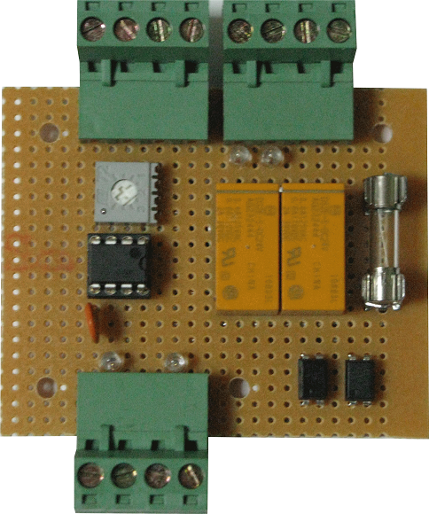
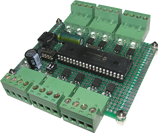
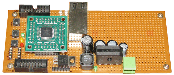
DC Motor Controller
 |
 |
Circuit layout and manually wired on an FR2 prototyping board.
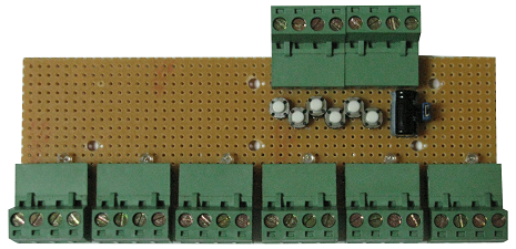
RS232 I/O Controller
 |
 |
 |
 |
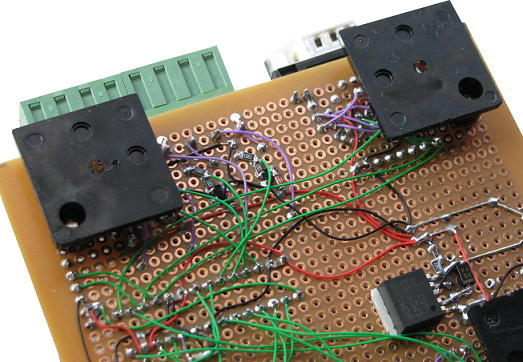
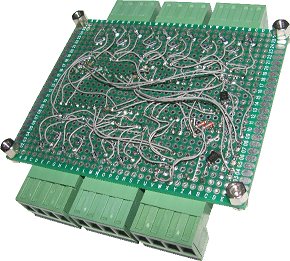
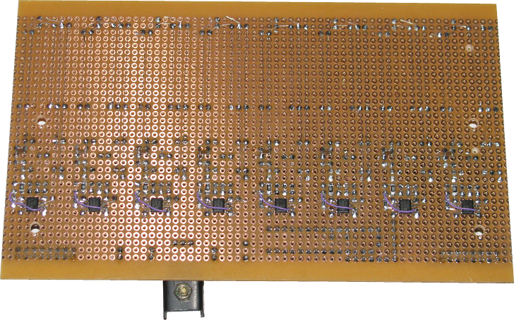
Circuit illustrating electronic circuit assembly using an FR2 prototyping board. The back side of the PCB showing point to point wire wrapping wire soldering. Soldering point to point is simple, and make good electrical connection. The connection is soldered onto the pin and will not easily disconnect.
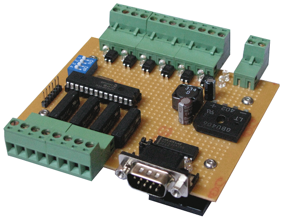
LED Backlight Driver Circuit
 |
 |
Alarm Notification RS485 Communication Prototype
 |
 |
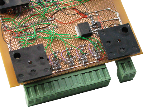
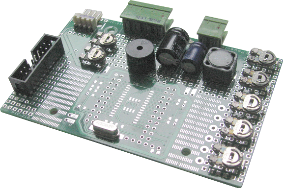
Neat custom component layout with the point to point soldering using wire wrap wires on an FR4 prototyping board. The FR4 board prototype boards have rows/columns of holes which are inter-connection on both sides of the board. The top of the PCB is neatly mounted with through hole components, while the back of the PCB has the electronic connection with the point to point soldering.
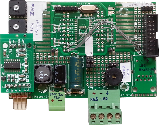
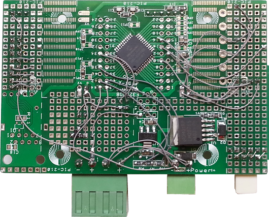
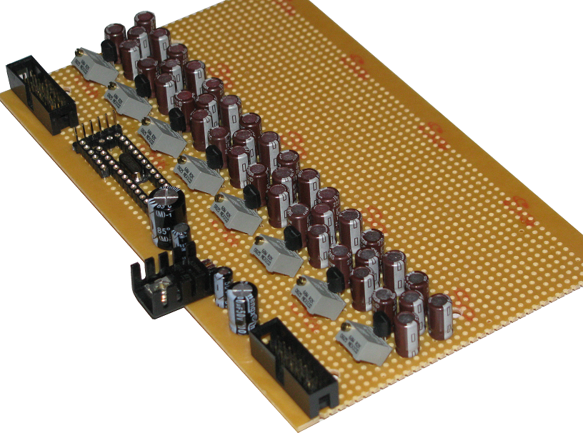
Load Cell Electronic Reader Circuit (Digital Weighting Scale)
 |
 |
 |
 |
|
|
|
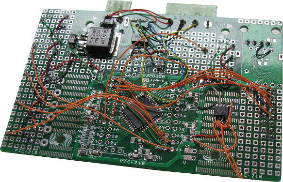
This is partial PCB and manual wiring connection on the PIC-210 prototyping board. The prototyping board is partially pre-connected to the standard connection, saving you time to manually connect them point by point while providing you with the flexibility of wiring for your electronic circuit prototype.
Visit the prototyping page for more information about PIC-210 prototyping board.
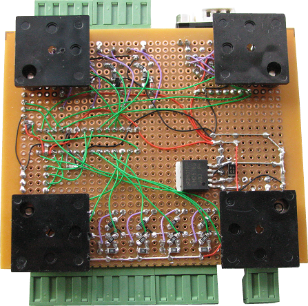
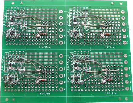
Magnetic Field Sensor Array
 |
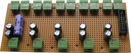
Manual wiring of an electronic prototype design can allow you to have tight component placement, which help keeps your board space small. |
 |
 |
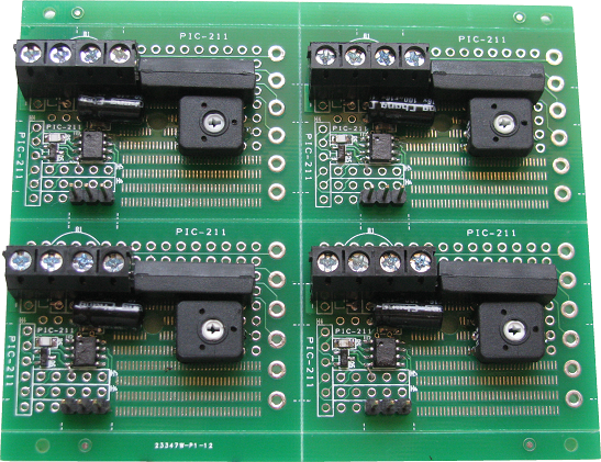
RFID Card Key Reader Prototype
 |
 |
 |
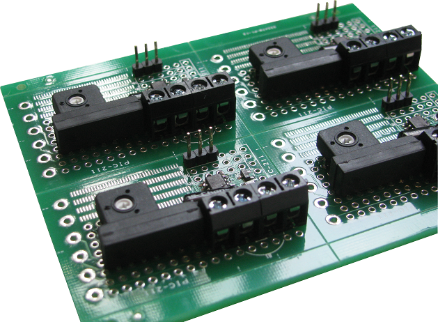 |
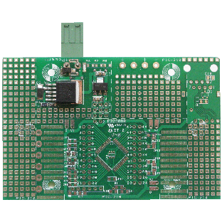
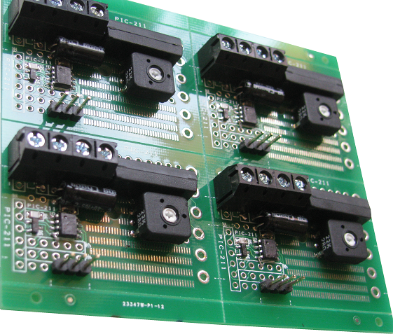
This is another prototyping board for microchip 6 to 8pins microcontroller series. Build up your prototype and customise the design by doing manual point to point wiring connection.
Visit the prototyping page for more information about PIC-211 mini prototyping board.