Introduction to DIY capacitive touch sensing, and the various type of touch sensor technologies.
Edited by Lim Siong Boon, last dated 14-Jul-09.
Topic Discussion Overview
- Touch sensor IC and product
- Touch sensor circuit
- Touch sensor in action
- Touch Vibration Motion Sensor
- Piezo Touch Sensor
|
1. Touch sensor IC and products
Various capacitive touch sensor products
Quantum Research Group Capacitive touch sensor QT100, QT102, QT110, QT113, QT118H, QT220, QT240, QT1081, QT1103, QT60160, QT60168, QT60240, QT60248, QT60326, QT60486, QT411, QT511, QT1106 Capacitive touch sensor: QST108, QST1610, STMPE1208S Resistive touch sensor: STMPE811 Capacitive touch sensor: B6TS-04LT, B6TS-08NF, B6TS-16LT Sensor Platforms Capacitive touch sensor: SSP1401, SSP1492 Analog Devices Capacitive touch sensor: AD7142, AD7143, AD7147, AD7150, AD7151, AD7745, AD7746, AD7747 |
The following
circuit DIY touch sensor will be focusing oncapacitive sensing method.
In case you think that capacitive is the only method to implement touch
sensing, I have done some searching and list down the possible method
and technology to achieve similar touch effect as the capacitive
method. Just a short brief of the various touch sensing technology
available in the market for your reference.
The various types of touch sensor. – Capacitive – Resistive “4 wire/ 5 wire/ 8 wire” – S.A.W “surface acoustic wave”, Acoustic – InfraRed – Camera
Capacitive type are normally used in a simpler button switch interface, which are commonly available on portable gadgets like mouse, ipod, and the On/Off switch for your LCD monitor. This method senses the changed of capacitance when the user come in close contact on the switch plate surface. Capacitive touch sensor can be implemented using microcontroller with simple interfacing component. You may like to refer to Microchip or Texas Instruments website for implementing touch sensing using a microcontroller, mTouch.
PDF Article: Layout and Physical Design Guidelines for Capacitive Sensing PDF Article: Software Handling for Capacitive Sensing PDF Article: Capacitive Multibutton Configurations
PDF Article: PCB-Based Capacitive Touch Sensing With MSP430
Fortunately there are already integrated hardware solution in the form of IC chip, making it easier to integrate touch sensing into your gadget. On the left are some references for the various source of IC chip.
The following are some of the touch solution available.
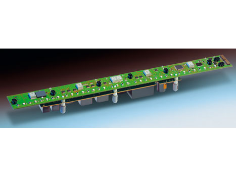
SAW acoustic sensor
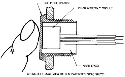
Piezo touch switch http://www.danielsoneurope.com/products/piezo_switches/
Cherry IR touch panel A simple IR emitter and detector for touch sensing.
Another method of detection using IR sensor, by sensing the lights that is being blocked (the IR component looks like a LED). http://web.ndak.net/jdgrotte/touchsensor/touchsensor.htm
IR sensor
deployed in grid form, creating a IR sensing touch screen.
Touch technology base on camera.
– IR camera.
more: http://www.instructables.com/id/How-to-Make-a-Cheap-Multitouch-Pad/1
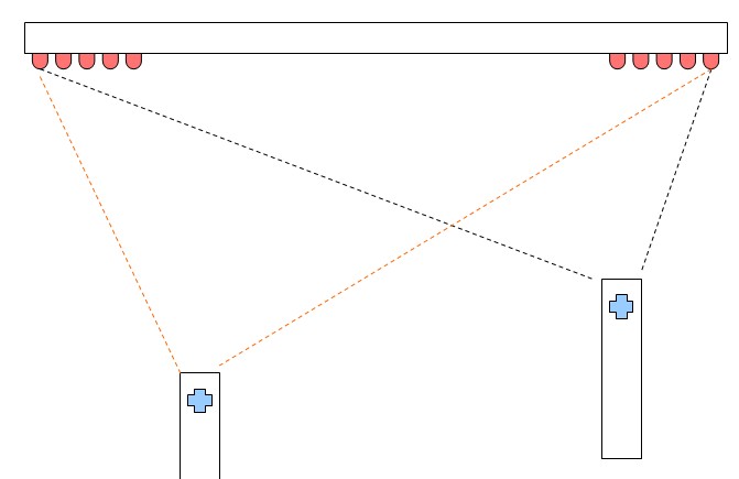
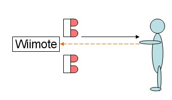
– Whiteboard using the Wiimote.
http://uiui.mmdays.com/2008/03/29/johnny-lee/
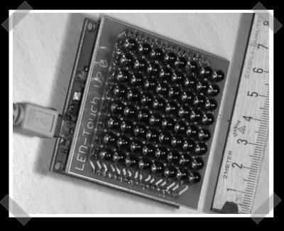
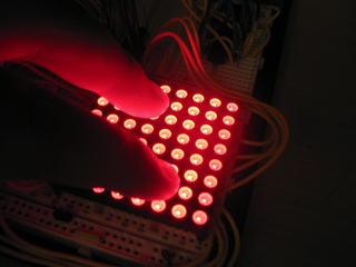
– LED Multi-touch panel (click the picture for reference)
Comparison references for various touch sensing technology. PDF Article: Touch Screen Technology Comparison http://www.tvielectronics.com/Touch_Screen.html http://www.softtouch.co.in/compareTouch.htm
|

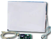
 Resistive touch sensor is
commonly deployed in our touch panel LCD monitor.
Resistive touch sensor is
commonly deployed in our touch panel LCD monitor.
 Acroustic sound sensing, by sensitive object.
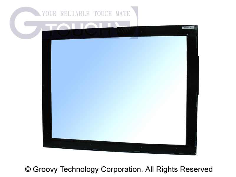

Singapore Customized, custom made Electronics Circuits & Kits
| 2. Touch sensor circuit | |
|
Simplest touch sensor circuit The illustration on the left shows a simple touch sensor circuit. It will light up the LED when a person gets in contact with the wire or metal connection to the transistor base. This touch circuit is cheap and easy to construct. All you need is a npn transistor, a resistor, a LED, a metal contact surface and of course the wire connection. It is so simple. NOTE: Interface the circuit will requires a bit further improvement to the design. Do not connect the ground reference to the earth. The LED will either not light up or will be very dim.
|
|
|
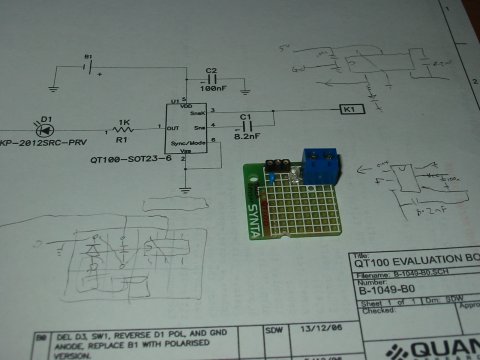
Capacitive touch sensor circuit using QT100
Touch sensor schematic. (click for larger image) |
Using QT100
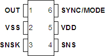
QT100 IC pin out
Part no. – AT42QT1011 (touch on output) – AT42QT1012 (touch toggle output) – AT42QT1010 (touch pulse output)
|
|
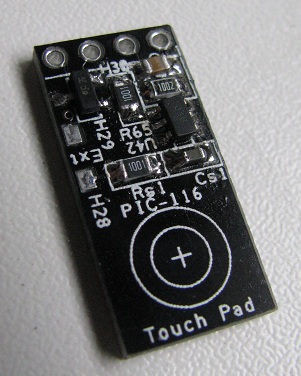
Touch Sensor Module PIC-116
click here to
|
This touch sensor module PIC-116 from PIC-CONTROL uses QT100 IC to sense touch. You can purchase this from PIC-store. The module is small measuring only about 21x10x3mm, making it easy to deploy for switch or button press application. The voltage supply Vcc required can be from 1.8V to 5.5V. There is two output provided. Pin 2 is a digital output logic 0 and logic 1. Logic 1 indicates a touch detected. Logic 0 will be a 0V, while logic 1 is a voltage that is same as Vcc (supply voltage). Pin 1 is a npn output; logic 1 will force this pin 1 to ground, while logic 0 will leave this pin floating. Pin 1 is useful if the application needs to drive directly a load of not more than 40V 0.5A. The load can be a LED indicator or the coil of a relay to drive higher current load. This means that it can be use as a momentary switch to switch on virtually anything. The touch sensitivity can be adjusted by changing the capacitor Cs. PIC-116 mini touch sensor module is installed with a Cs value of 8.2nF. The sensitivity can be reduced by using a lower capacitance value Cs; minimum Cs value is about 2nF. A Cs value lower than 2nF can have undetermine output state. To increase the sensitivity, a higher capacitance of Cs can be used. Maximum Cs value is about 50nF. The sensor can be so sensitive that it can detect your finger or body a few centimeter away from the sense pad. |
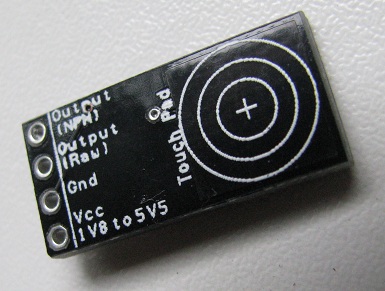 |
The reverse side of the PIC-116 touch sensor module is completely flat, making it easy to hide and stick behind a glass or plastic plate as a user interface. The intergrated sense pad onboard is on this side of the board labelled by the 3 circled ring with a pad area of about 10x10mm. |
|
|
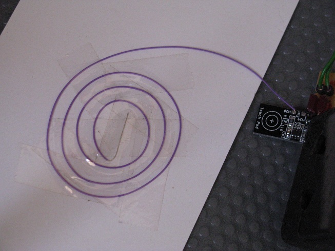
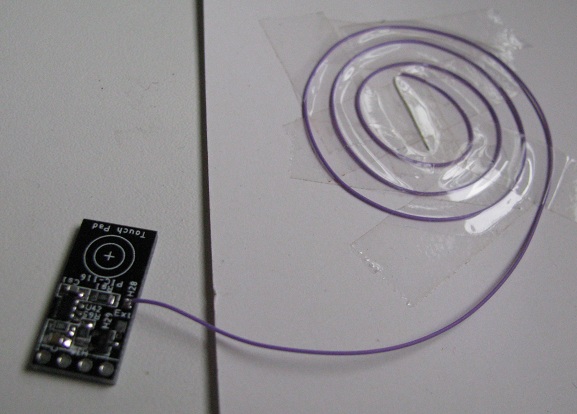
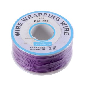
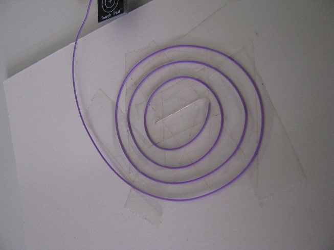
The sensor comes with a soldering pad to allow me to use my own sensor pad. I have coil a length of fine wire wraping wire (thickness 0.5mm) as a touch pad. One end of the fine wire is soldered to the pad labelled as “Ext”, which is also next to the component Rs. This coil allows me to customised my own touch pad with varies size and shape. The coil on the left is about a diameter of 50mm. A big touch pad makes it easy for a user to interact with.
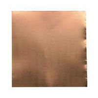
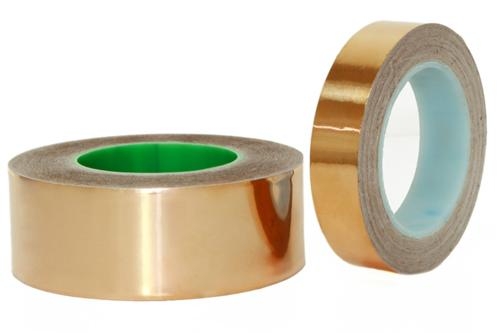
Alternative, this “Ext” pad can be soldered to copper foil or copper tape (thickness 0.08mm) which can be much thinner than my wire wrapping wire. A flat touch pad can be easily conceal behind poster or PVC stickers, allowing the touch switch to be hidden flat. This is great if you need an odd size/shape/surface switches as a user interface to blend into your designed artifact; which is impossible using a typical off the shelves mechanical push switches. Compare to a mechanical switch, touch switch do not have the problem of mechanical wear and tear. You can get the copper foil from stained-glass shop. Copper foil tape is used as adhesive to allow the solder to hold the glass that was cut to shape.
copper foil, copper foil tape, easily available from stained-glass shops After my external wire coil is soldered onto the “Ext” pad, the sensor becomes more sensitive. This is due to the increase in the pad area. The larger the pad size, the more sensitive it will become. The larger pad surface allows the sensor to capture from a larger area. In order to reduced the sensitively, a smaller capacitance Cs can be use. The touch pad should be of a size of the sense target. If the finger is expected to touch the pad, the pad size should be of the finger size which is about 10x10mm. If a palm/hand/leg touch is expected, the sense pad can be larger. |
|
|
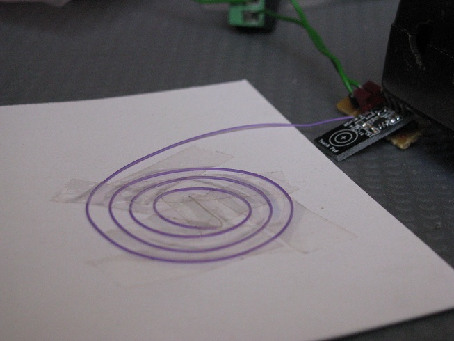
Sensor will not response when nothing is near its sense pad. |
 |
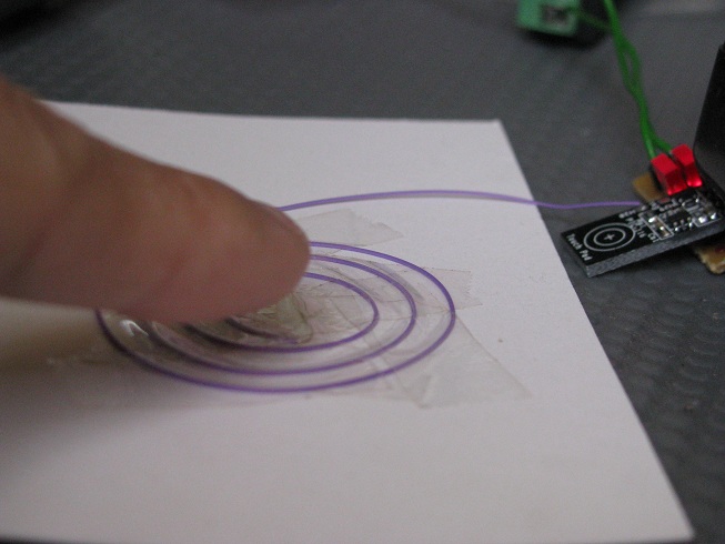
Sensor detects my finger at a close proximity to the pad. A physical touch is not neccessary; it depends on the sensitivity that was set by the capacitor Cs. The sensitivity can be set lower, so that the sensor gets activated only upon a physical touch on the sense pad. |
|
Video of the touch sensor PIC-116
|
click here to |
| Various
others touch circuit that I have found on other website:
|
|


Singapore Customized, custom made Electronics Circuits & Kits
|
|
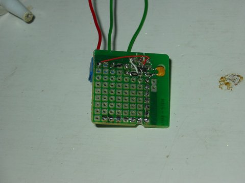
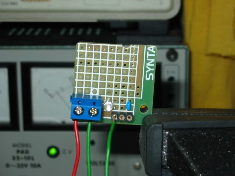
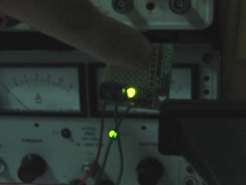
Testing out with
my first touch sensor prototype board. It is actually more sensitive
than expected. The sensor board can sense my finger at a distance of
about 10mm. The circuit is quite simple to setup with only a few
passive resistor and capacitor components.
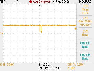
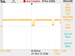
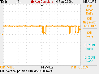
I am suppose to make the board a plate for sensing the capacitance, but I only wired the sensing plate in a form of L shape path. It is working well just like a rectangular sensing zone, even though the plate is actually a thin L shape path. One thing I found out. It is too sensitive. the sensor also detects if I place the board near my wooden table platform. You can actually fine tune the sensitivity by using a different capacitance component. Try reading the datasheet for further information on using QT100 touch sensor. You can find more tips on making your own touch sensing device. The following videos demonstrate the signal out put you can expect from QT100 touch sensor IC. Touch sensor is sensitive |
|
4. Touch Vibration Motion Sensor
|
|
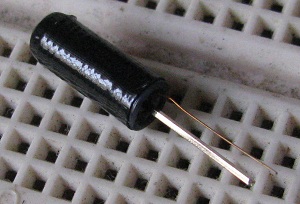 |
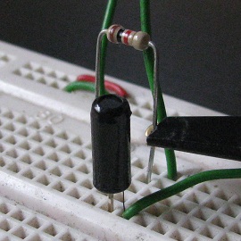
This is a simple vibration detection switch. The switch will make a contact upon slight vibration or motion. Typical application for this sensor click here to
|
|
A simple schematic of the vibrate sensor circuit under testing.
|
The picture and schematic on the left presents a simpe circuit to test the sensor. The output signal is a digital on and off signal, like a random noise or glitches. The change of signal’s logic indicate that there is a vibration or knock present. The output state of the sensor at rest will be logic 1 (5V); the sensor is a open switch at rest position. When the sensor is subjected to a centrifugal force, the sensor will be at close position, with its output staying constant at logic 0 (0V). The output signal is quite raw, but can be easily intepreted from a micrcontroller to detect the vibration event. |
|
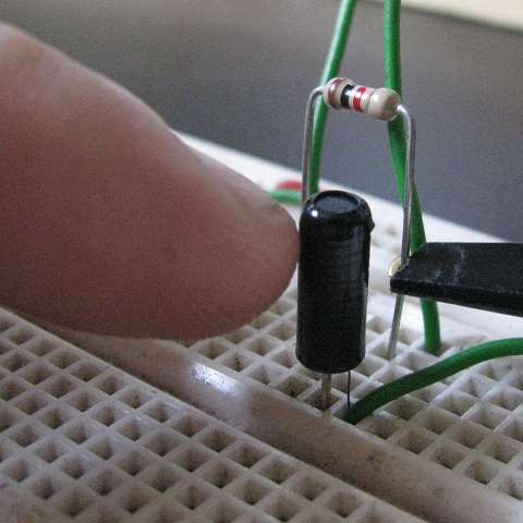
My finger giving the sensor a slight knock.
|
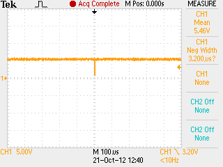
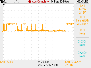
The sensor is a very sensitive touch switch. Any finger knock on the physical sensor will trigger an output response. The following signal is taken from the output signal of the vibrate sensor. The output signal of various knock and vibration. Some slight touch, while some very hard hit on the sensor.
|
|
|
A permanent logic 1 or 5V will occur when the sensor is subject to a centrifugal force. |


|
|
Touch sensor using piezo was what I would have never though of. I know the many use of piezo, but using it as a touch is over-whelming to me. I have searched the website for more information about piezo, and managed to consolidate them below. |
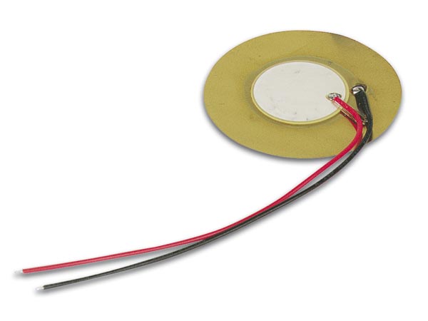  |
This is how a plain piezo sensor looks like. It consist of two plate which can bend with input voltage (use as a speaker), and generate voltage when bend (use as a microphone). |
 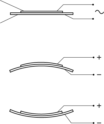 |
Using piezo as a buzzer. Alternating voltage is applied to the wire pair which will vibrate the sensor. In simple sense, it works like a speaker.
A illustration of how the piezo sensor, 2 plate generate voltage when bend or how it bends when voltage is applied. |
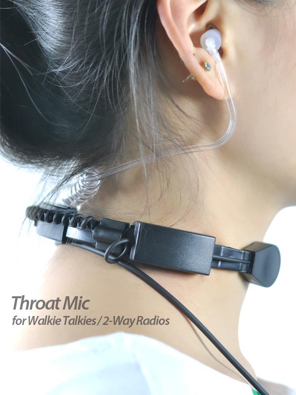 |
Throat microphone using piezo. Normal microphone depend on the sound wave through the air. Sometimes noise from a distance can be pick up by the mic. A throat mic is held close to the throat, picking up the vibration from our voice. This can prevent the distance noise from being pick up, but it also has its own source of noise. Anything that can vibrate the throat mic will be the potential source of noise for the throat mic. |
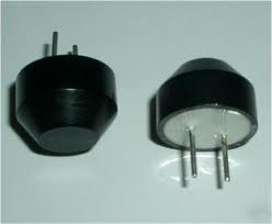 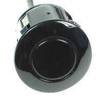 |
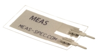
Ultrasonic Transducer using piezo plate. This sensor is widely deploy on a vehicle as a parking sensor. The sensor will activate a warning buzzer when it detect an object behind the vehicle. The sensor generate an ultrasound wave and any object in the path of the wave will reflected the sound wave back to the sensor. A detection of the reflected sound will indicate an object in front of the sensor. It works is like the bat flying in the dark using their ear to navigate. |
|
taken from http://piezo-switch.com/index-2.html
|
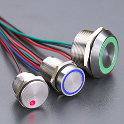
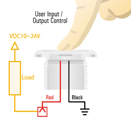
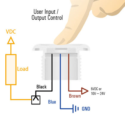
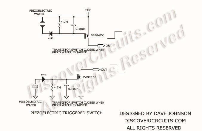
Piezo sensor as a touch switch. Using piezo as a touch switch has many advantages over other type of sensors. – durable, waterproof – easy to maintain, long lifespan – robust to RF, capacitance interference. |
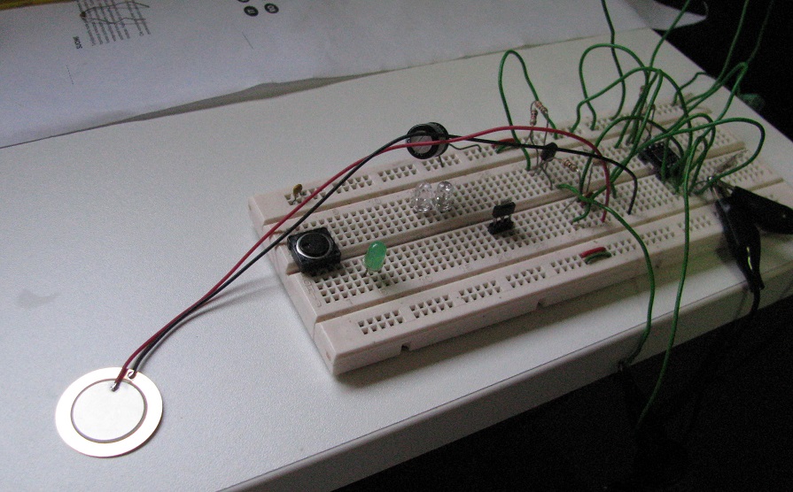
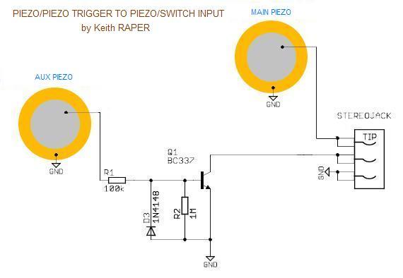
| The piezo schematic that I have tried out: | My flat and ultra thin user button switch. |
|
|
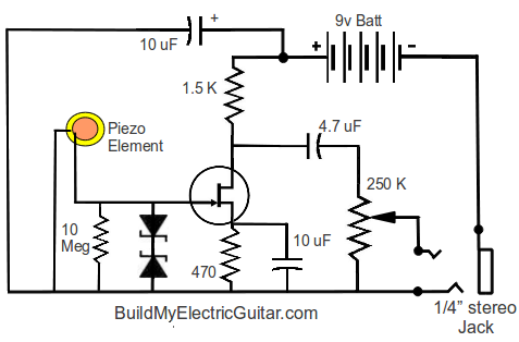
Schematic making use of piezo plate as a touch button push switch. Switch will get activate with a light tap on the piezo plate.
A simpler schematic to use the piezo plate as a switch.
|
|
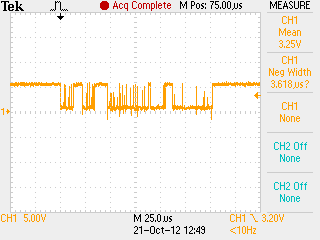
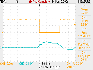
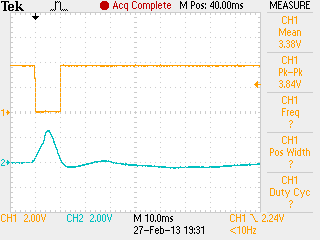
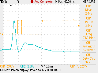
Some of the signal taken on the piezo output and also the processed switching signal.
|
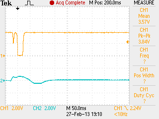
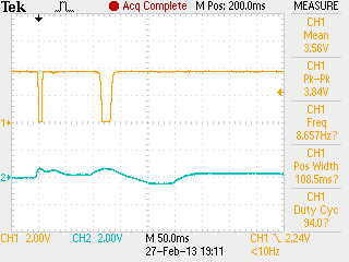
Ch1 (yellow) is the npn transistor output. Ch2 (blue) is the signal taken at the piezo out. Signal can reach as high as a few volts. When pressure is applied to the white ceramic back side, the signal will start off with a positive curve, followed by a negative smaller curve. The opposite signal will be generated if the pressure is applied from the front face.
I managed to play around with various design. Some design, the signal decay slowly which result in glitches. Overall the piezo is quite simple to interface. Vibrate can activate the sensor, but not as bad as I had imagine. This undesirable noise can be filtered with proper design. |
|
|
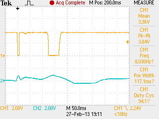
Signal taken with my final op-amp schematic design as posted above. The square pulse has a much cleaner cut. |
|
Piezo touch sensor circuit taken from other website
|
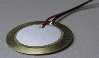 ceramic back side of the plate.
 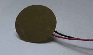 front side of the plate.
 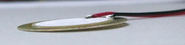 side view showing the piezo, a very thin
plate.
side view showing the piezo, a very thin
plate.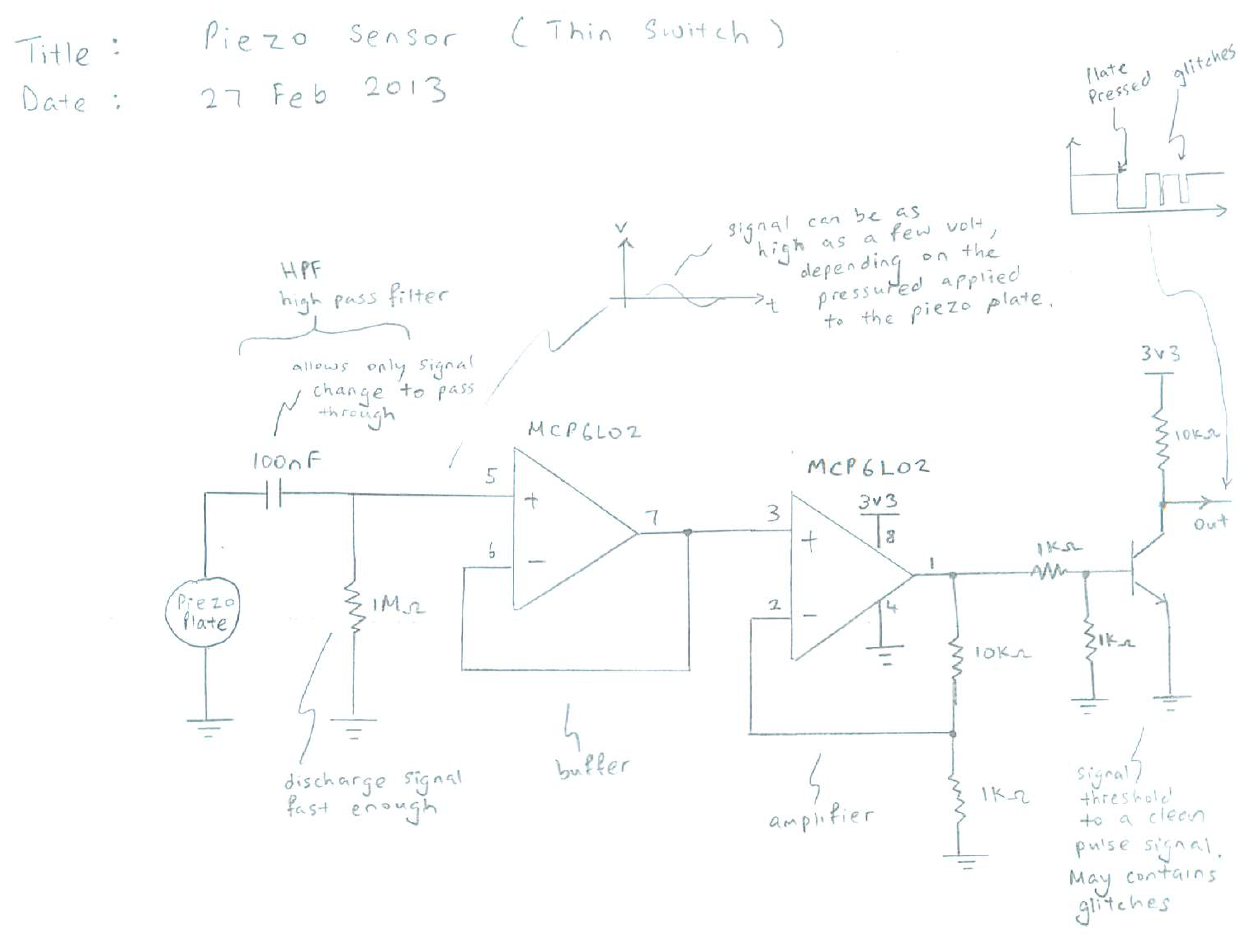

Keyword: Touch sensor switch, proximity, capacitance, capacitive touch sensing, surface acoustic wave, resistive 4 wire 5 wire