Your reference guide to analog electronics for your electronics projects.
Edited by Lim Siong Boon, last dated 06-Jul-08.
Short cut to your reference guides and charts
| Op-amp | |||||||||||||||||||||||||||||||||||||||||||||||||||||||||||||||||||||||||||||||||||||||||||||||||||||||||||||||||||||||||||||||||||||||||||||||||||||||||||||||||||||||||||||||||||||||||
 |
Op Amps for Everyone, by Bruce Carter and Ron Mancini from Texas Instruments. op amps for everyone (Texas Instrument).pdf op amps for everyone third edition 2009 (Texas Instrument).pdf
Op-amp application notes from National Semiconductor, An applications guide for op-amps.pdf
Single rail op-amp design from Texas Instruments single power supply design.pdf
Various precision op-amp rectifier design. http://sound.westhost.com/appnotes/an001.htm From National Semiconductor and Texas Instruments op_amp_circuit collection_AN-31.pdf snla140a, Op Amp Circuit Collection.pdf Others op-amp awith offset (bias).pdf Single Supply Op Amp Design.pdf CH9 Paul Smith notes.pdf
|
||||||||||||||||||||||||||||||||||||||||||||||||||||||||||||||||||||||||||||||||||||||||||||||||||||||||||||||||||||||||||||||||||||||||||||||||||||||||||||||||||||||||||||||||||||||||
Type of Op-amp circuit
|
|||||||||||||||||||||||||||||||||||||||||||||||||||||||||||||||||||||||||||||||||||||||||||||||||||||||||||||||||||||||||||||||||||||||||||||||||||||||||||||||||||||||||||||||||||||||||
Op-amp Selection
(cheap precision op-amp) Precision
usually means a low input offset voltage, which is quite important for
voltage comparator, or amplifying small differential input signal. |
|||||||||||||||||||||||||||||||||||||||||||||||||||||||||||||||||||||||||||||||||||||||||||||||||||||||||||||||||||||||||||||||||||||||||||||||||||||||||||||||||||||||||||||||||||||||||

Singapore Customized, custom made Electronics Circuits & Kits
The following article is a simplied understanding of signal filtering. Basic knowledge of signal filtering is still required before reading this section.
|
Other references for signal conditioning / filtering Analog Sensor Conditioning Circuits – An Overview – 00990a.pdf (from Microchip) |
||||||||||||||||||||||||||||||||||||||||||||||||||||||||||||||||||||||||||||||||||||||||||||||||||||||||||||||||||||||||||||||||||||||||||||||||||||||||||||||||||||||||||||||||||||||||||||||||||||||||||||||||||||||||||||||||||||||||||||||||||||||||||||||||||||||||||||||||||||||||||||||||||||||||||||||||||||
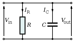
The simplest signal low pass filter (LPF) is presented on the right consist of a resistor and capacitor. It is commonly known as RC filter. This RC layout is applied to circuit with low impedance input, high impedance output. The resistor will be required to complete the filter function. Signal oscillation may occured is the resistor is omitted. One example would be LPF filtering at the output of the op-amp amplifier circuitry, where filtering is applied to the varying input signal/voltage. The cutoff frequency of this RC filter R will need to be significantly small compare to the load. If the load impedence is high (infinity), then the value of R becomes not very important. If the load impedence is finite, R should be smaller than 1/10 of the load. Click here for the calculator for the LC filter. frequency and time domain results are on the fly. |
Ideal analysis of the circuit What the high frequency signal will see: What the low frequency signal will see: Please note that the above explaination is a simplfied analysis of a filter. Ideal analysis helps us to understand the circuit topology (function) at a glance without the need for detail computation. In reality, the open/short circuit represent the degree of attenuation faced by the signal. The degree of signal attenuation is dependant on the frequency of the signal and the capacitor’s capacitance.
|
||||||||||||||||||||||||||||||||||||||||||||||||||||||||||||||||||||||||||||||||||||||||||||||||||||||||||||||||||||||||||||||||||||||||||||||||||||||||||||||||||||||||||||||||||||||||||||||||||||||||||||||||||||||||||||||||||||||||||||||||||||||||||||||||||||||||||||||||||||||||||||||||||||||||||||||||||||
This is another low pass filter consist of only a capacitor. This type of filter will work for current source input. Vin = Vout. One example would be the capacitors that are found on typical dc power supply filtering at its input or output. Decoupling capacitors (100nF) that are normally found near the power input of an IC is also another example.
|
 A capacitor as a low pass filter. A capacitor as a low pass filter. |
||||||||||||||||||||||||||||||||||||||||||||||||||||||||||||||||||||||||||||||||||||||||||||||||||||||||||||||||||||||||||||||||||||||||||||||||||||||||||||||||||||||||||||||||||||||||||||||||||||||||||||||||||||||||||||||||||||||||||||||||||||||||||||||||||||||||||||||||||||||||||||||||||||||||||||||||||||
| This is a simple high pass filter (HPF) using resistor and capacitor (RC) components. The ideal analysis is similar to the LPF as anaylzed eariler, allow high frequency signal to pass through while low frequency signal are attentuated. | 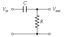 RC filter, the simplest high pass filter. RC filter, the simplest high pass filter. |
||||||||||||||||||||||||||||||||||||||||||||||||||||||||||||||||||||||||||||||||||||||||||||||||||||||||||||||||||||||||||||||||||||||||||||||||||||||||||||||||||||||||||||||||||||||||||||||||||||||||||||||||||||||||||||||||||||||||||||||||||||||||||||||||||||||||||||||||||||||||||||||||||||||||||||||||||||
Capacitances required to attenuate or suppress signal of certain frequency. Please note that this formula and the table presented on the right is an approximation for filtering noise from a DC signal.
Xc = 1 / (2π f C) C = 1 / (2π f Xc ) where Xc is the reactance of the capacitor. Xc of 1.0 for the capacitor (open circuit) is possible with lower fequency signal or lower capacitance. To attenuate the AC signal of a particular frequency, Xc has to be low with the correct capacitance implemented.
Example: To attenuate a 50Hz signal by 10 times. C = 1 / (2π x 50Hz x 1/10) = 31,830uF This means that to attenuate the 50Hz component by 10 times requires about 33,000uF capacitor connected from the signal to the ground line. This capacitor will filter any frequncy >50Hz on the line. The table on the right is a simplified guide, which recommend the capacitance to use as a low pass filter for attenuating a particular frequency. |
Max frequency for capacitor (taken from “Op Amps for Everyone”)
|
||||||||||||||||||||||||||||||||||||||||||||||||||||||||||||||||||||||||||||||||||||||||||||||||||||||||||||||||||||||||||||||||||||||||||||||||||||||||||||||||||||||||||||||||||||||||||||||||||||||||||||||||||||||||||||||||||||||||||||||||||||||||||||||||||||||||||||||||||||||||||||||||||||||||||||||||||||
| The table on the right summeries the typical capacitor value available commercially. | Standard Commercial Capacitor Value:
|
||||||||||||||||||||||||||||||||||||||||||||||||||||||||||||||||||||||||||||||||||||||||||||||||||||||||||||||||||||||||||||||||||||||||||||||||||||||||||||||||||||||||||||||||||||||||||||||||||||||||||||||||||||||||||||||||||||||||||||||||||||||||||||||||||||||||||||||||||||||||||||||||||||||||||||||||||||
Active filter with op-amp For flat frequency response, use Butterworth filter For a sharp cutoff frequency, use Chebyshev filter For linear phase, use Bessel filter. |
|||||||||||||||||||||||||||||||||||||||||||||||||||||||||||||||||||||||||||||||||||||||||||||||||||||||||||||||||||||||||||||||||||||||||||||||||||||||||||||||||||||||||||||||||||||||||||||||||||||||||||||||||||||||||||||||||||||||||||||||||||||||||||||||||||||||||||||||||||||||||||||||||||||||||||||||||||||
 RC filter, the simplest low pass filter.
 Another way of looking at the same RC filter.

Singapore Customized, custom made Electronics Circuits & Kits
| Transistor Switching | |
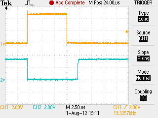
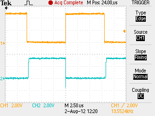
I didn’t realised that transistor switching speed can be so important until I had encountered a problem using it for SPI communication. The data communication gets corrupted. Go through all the codes, and eventually found that the transistor switching speed was slow. The current batch of transistor is different from my previous batch; and I always thought that all BC817 npn transistor is the same. I am wrong, it is not. The problem might have been due to my design as well, unable to discharge the base signal in time, to turn off the transistor. Ch1(yellow) shows the signal input through a 1kohm resistor to the base of the npn transistor. Ch2(blue) is the output at the transitor’s collector terminal, with a pull up resistor of 560ohm. The is The following present the various BC817 transistor’s switching digital speed. |
|
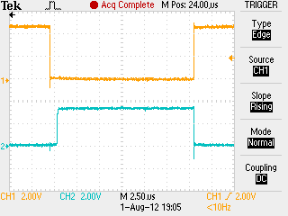 |
Switching speed of my original transistor. delay of about 0.7us. |
 |
using npn BC846 delay of about 2us. |
 |
using npn BC817 delay of about 2.5us. |
 |
BC817-16LT1G delay 2us |
 |
MMBT4401LT1G delay 4.5us |
 |
MMBTA05LT1G delay 0.25us |
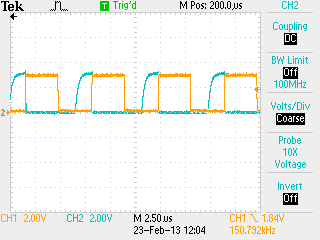 |
Effect of the signal switching without a resistor across the Vbe terminal of a npn transistor BC817. |
 |
Effect of the signal switching without a 10kΩ resistor across the Vbe terminal of a npn transistor BC817. There is a slight improvement in delay, but not very noticable. |
 |
Effect of the signal switching without a 10kΩ resistor across the Vbe terminal of a npn transistor BC817. More than 100% improvement shortening the delay, of the inverted signal by about 1us. |
Keyword: op-amp, buffer, inverter, amplifier