Convert your existing alarm to be mute for a period of time. Allows you to acknowledge the alarm situation, to silent your alarm temporary.
Wiring Connection
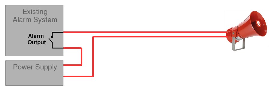
Existing alarm wiring connection
Adding on PIC-124 Alarm Mute Switch to your existing alarm setup
*** Please note that the input port can only accept dry contact input. (eg. a passive switch or passive output of a relay).
The output port is only a simple relay output. Please check if the rating is suitable for your use.
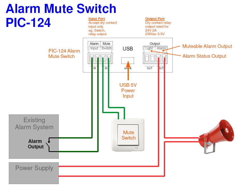
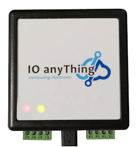
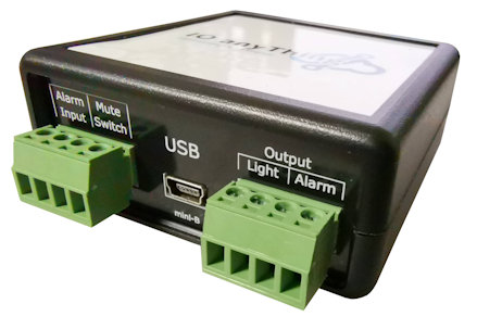
PIC-124 Description
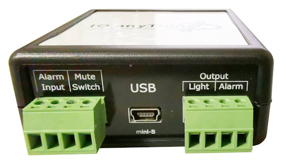
- USB – Power supply input for the device through a USB mini-B cable. (5V 0.5A)
- Alarm Input – Notification from the external alarm system.
- Mute Switch – Switch input for muting the alarm.
- Output Light – Alarm status output. (Output follows Alarm Input)
- Output Alarm – Alarm output which can be mute by the mute switch.
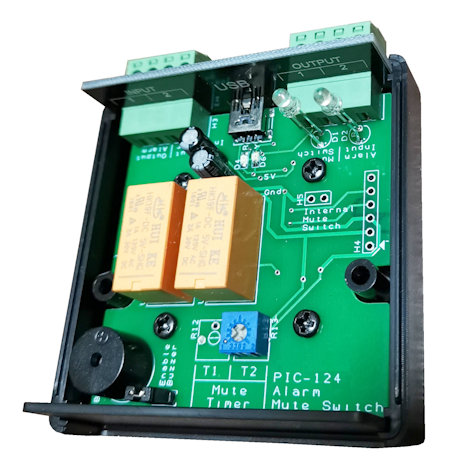
Note: There is an internal buzzer build in the device PIC-124. The buzzer can be disabled by pulling out the jumper on the circuit board inside the enclosure.
Operating Instruction
Simple step-by-step operation guide
- Connect up the PIC-124 Alarm Mute Switch wiring connection.
- Alarm Input activated.
- Both Output Light & Output Alarm will be activated.
- Pressing on the Mute Switch will deactivate the Output Alarm for 3 minutes.
- After 3 minutes, Output Alarm will be activated again.
When Alarm Input is not active, both Output Light & Output Alarm will also get deactivated.
Adjust the mute timing
You can adjust the mute timer anywhere from 1 to 128 minutes.
Fully turned anti-clock wise is 1 minutes. Fully turned clock wise will be 128 minutes.
The resolution is about 1 min.
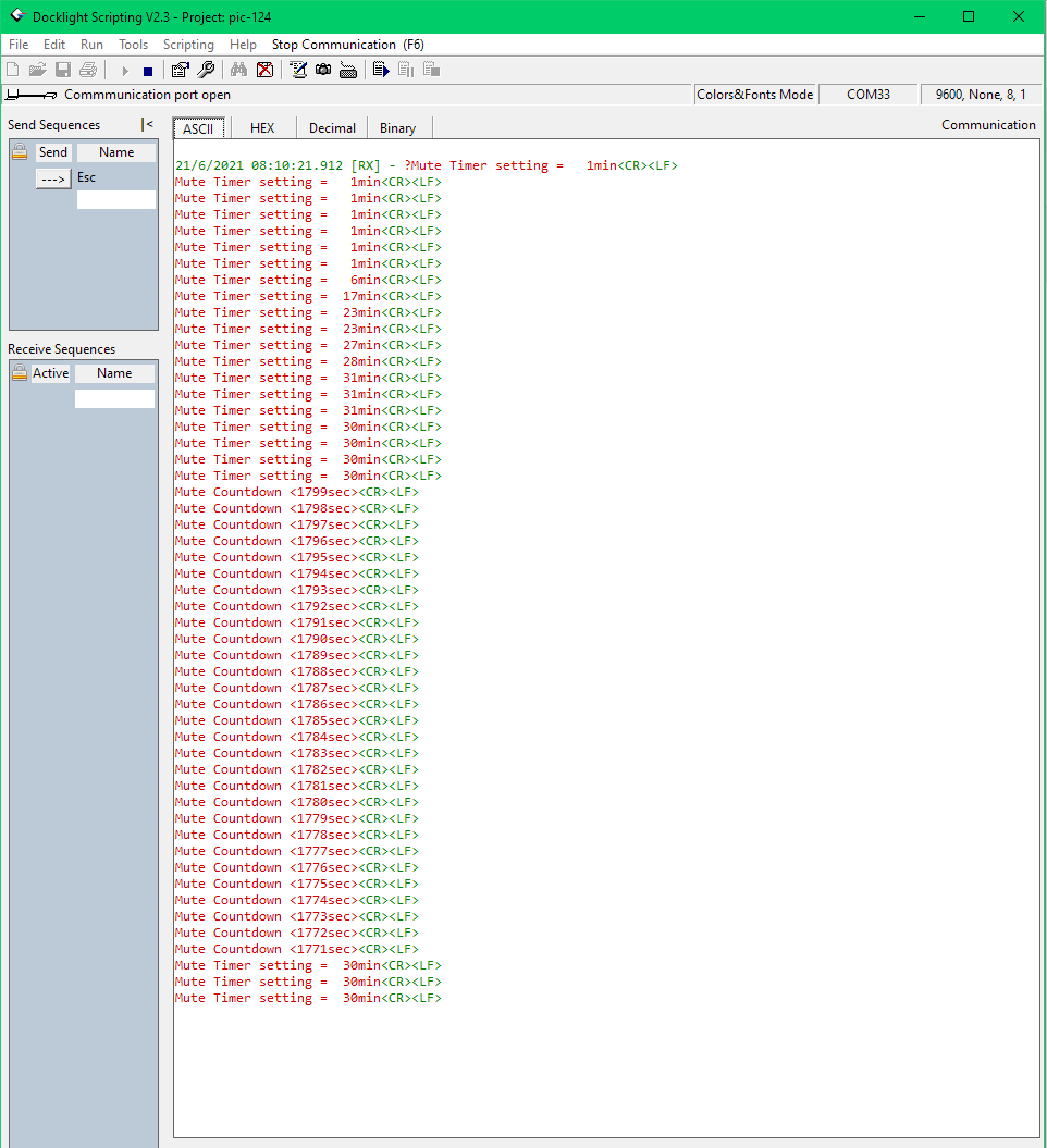
You can actually connect the USB port to your computer system. This will create a virtual serial communication port on your computer which allows you to see the exact mute timer timing that you have set on this device.
Baudrate: 9600bps
Data: 8 bits
Stop: 1 stop bit
Parity: None
No hardware handshaking.
When the mute switch is activated, you can also see from the data stream, the counting down on this mute timer device.
You can click on the screenshot image to have an idea of how the data looks like.
eg.
Mute Timer setting = 1min
Mute Countdown < 60sec>
Product Specification
- Power up from 5V USB power supply. (USB-C)
- Output relay contact rating is 24Vdc 2A, 230Vac 0.5A
- Build in buzzer (can be enabled or disable)
- A panel mount switch can be solder and install on the casing if preferred.
- Alarm Input can trigger back the alarm even when muting is in operation.
- Adjustable Mute Timing (from 1 to 128min).
- Edge Triggered Mute switch (Prevent personnel from muting the alarm permanently by jamming the switch).
- Re-triggering of the mute time period.
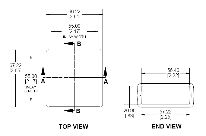
Dimension
More Alarm Mute Products
or contact PIC-CONTROL for further information.
Reference: