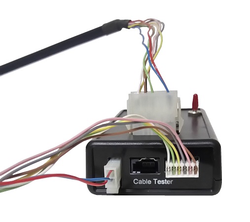
Cable tester, custom design for cable harness assembly production.
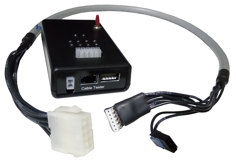
An operator can just simply plug in the cable connector to the tester to check for the cable harness assembly automatically.
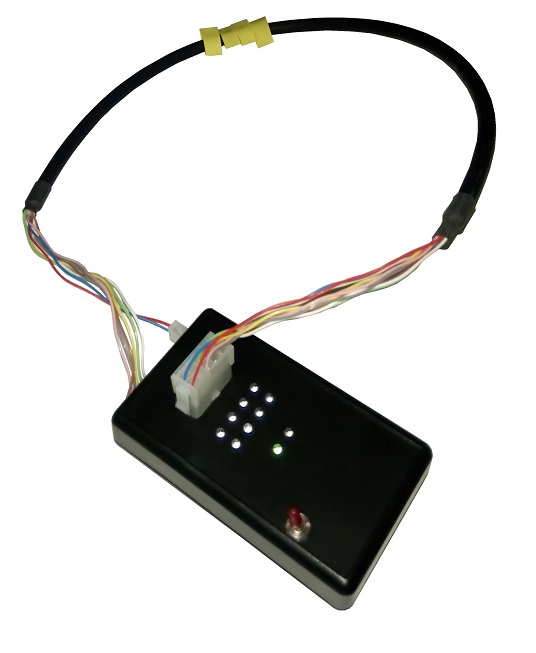
An audible beep will be sound immediately after the operator plug-in the connector. This indicates that the cable’s wiring is correct. The operator can simply focus their vision on the manual connection work.
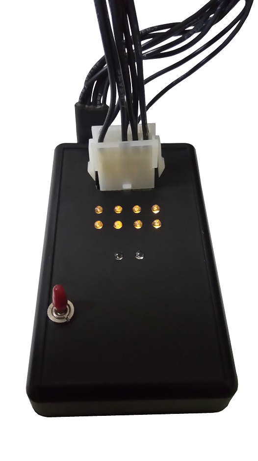
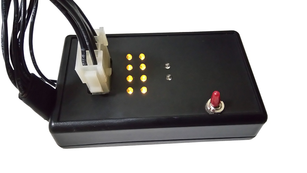
If there is no sound heard after plugging in, the cable’s wiring is probably incorrect or faulty. There will be LED indicator (orange colour) for each of the respective wiring. If any LED remains lighted up after plugging in the connector, they indicate a wiring fault. The fault due to the following,
- incorrect pin connection.
- the wire break resulting in a broken electrical connection.
- the connector is not properly crimped or soldered.
This custom tester has a monitoring mode which is designed to catch intermediate break wire connection that may be potentially existing in your the cable assembly. Intermediate wire connection fault can be due to a broken wire or cable that is not properly assembled. The fault may occur when the cable is touched or bend too much.
When all the connectors are connected to the cable tester, the tester will automatically enter into a monitoring mode. You should be able to hear 2 special beep sound which indicates that the tester is now in the monitoring mode. In this mode, all connectors are connected to the tester. Any connection break in the process of monitoring will trigger an error from the cable tester device.
To test your cable assembly in this mode, you can simply shake up the whole cable. The shaking can help to bring out any intermediate connection problem if there is any. You should see an error LED indicator (Red) lights up together with a long Error tone if an intermediate connection break is detected. The respective wire connection indicator (Orange LED) will also be displayed to indicate the exact wire that is having the intermediate connection problem.
Features of the Cable Tester [PIC-023]
- Simple to use.
- Instant audio beep and flashing LED light (Green) when the cable is plugged in, to indicate that the cable has passed the checking.
- LED indicator (Orange) will remain lighted to pinpoint faulty wires
- Able to catch potential intermediate connection fault in the cable.
- LED (Red) and long buzzer tone to indicate detected cable problem.
- Portable and can be designed to power up from USB power supply or from the battery.
Operating Procedure
- Plug in USB power cable, or insert batteries.
- Switch on the cable tester to power up. A test sequence will run to show that the buzzer and all the LED are working.
- Plug in one side of the cable onto the tester.
- Plug in the other side of the cable. The cable tester will detect the connection and begin testing the cable.
- A double beep sound and flashing Green LED indicates that the cable is tested ok.
- The respective LED indicator (Orange) for each of the wiring will diminish if the connection is mated correctly.
- If there is no sound heard after plugging in the cable, the cable is probably faulty. Check on the respective wire indicator (Orange LED) to determine the exact wire that is faulty. 1 or more LED should be lighted up which indicates incorrect or no connection.
- After the cable is all connected to the cable tester and has passed the wire connection test, the tester will enter into a monitoring mode. You should hear 2 special beep, followed by a blinking light from the green indicator, which tells you that the tester is now in the cable monitoring mode.
- In this cable monitor mode, you can continue to test the wired connection of your assembled cable harness. Shake your cable to see if there is any intermediate connection fault can be caught. If a glitch is detected due to the intermediate connection break, the cable tester device will be able to catch it. A long beep and error indicator (Red LED) will be lighted up. The respective wire indicator (Orange) will also be lighted up to pinpoint the exact wire that is causing this intermediate connection problem.
- The caught wire glitch fault will remain until all the wires are disconnected. The cable tester will then reset the test procedure.
- The operator can proceed to test the next cable harness set.
Other Optional Specialised Test Features
For dedicated wiring for precision/importance use, there are optional test that we can design to help you detect potential faults in your cable harness wiring.
The following are some of the specialised test that you may need to test on your assembled cable beside the basic connectivity check.
- Ohm test or resistivity test for your wires and connectors, to check if the wires are crimped or fasten properly.
- High voltage test, to ensure the wires are properly insulated.
- High-speed data or RF test to ensure signal integrity quality of your assembled cable.
Custom Electronic Tester
Contact PIC-CONTROL for further information for your custom cable tester.
- Cable harness connector connectivity tester
- Cable Harness Tester Equipment
- Production test jig for part assembly
- Custom test switch box
- IDC Cable Tester
- Custom Cable Tester