PIC-031 MDB Pulse Converter
Content
Click here to go back to product page.
Board Description
This board run the protocol basic MDB function at level 1.
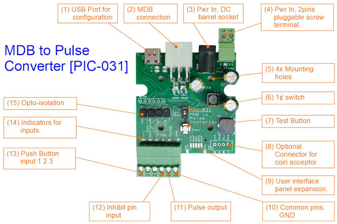
- USB-C Port, for device configuration and troubleshooting use.
- MDB Connection to an MDB Payment Terminal
- Power Input (DC barrel socket, 2.1mm)
- Power Input/source (2 pins pluggable screw terminal)
- Mounting holes for M3 screw.
- 1¢ Test Mode (system testing using 1¢ real money)
- Test Button to test for Pulse Output. (also a configuration and a reset button)
- (Optional) standard Coin Acceptor connector
- (Custom) User panel expansion
- Common GND pin for the input/output
- Pulse Output to trigger machine
- Inhibit pin to halt input or void transaction.
- Button Input (IN1, IN2, IN3).
- Indicators for the respective input and output.
- Opto-isolated inputs protection.
Typical Connection
A typical connection using this PIC-031 board consists of
- Power Supply Input (range from 9Vdc to 24Vdc)
- MDB connection to an MDB Payment Terminal
- At least a button input, up to 3 buttons.
- and lastly, the Pulse Output line to signal to the machine.
The following wiring diagram shows how PIC-031 MDB to Pulse Converter can be connected to your existing coin acceptor system to convert your machine for an MDB cashless payment terminal system. Both cashless systems and coin acceptor systems can co-exist. This means that your customer can pay using the existing coin system and also pay via the new cashless system.
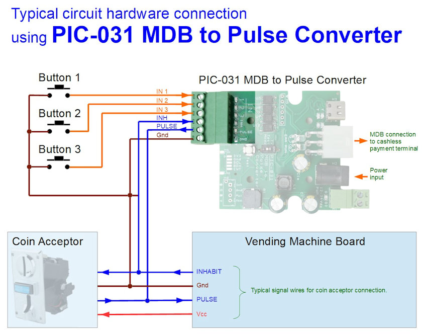
The power supply input can accept voltage ranging from 9Vdc to 24Vdc. You can supply power to the board via the DC barrel socket (black color connector) or the 2pin pluggable screw terminal (2 pins green color connector).
The payment terminal that is connected taps its power from this PIC-031 board. So it is recommended that the same power supply used for your payment terminal be plugged onto this PIC-031 board. The power adaptor should have enough power to power up both the PIC-031 board and your payment terminal.
The MDB connection is one of the common standards used in the vending machine industry. It consists of a Molex Mini-Fit Jr 5569 series 6 pins connector (part number: 39-30-1060). For further information on the MDB connector pin-out, you can click here to refer to this page.
The PIC-031 board can connect up to 3 push-button inputs. This allows you to set up for 3 types of item pricing or selection. You can also set to a single-price mode where user need no have to press any no button. User simply tap for payment and the board will trigger the machine. Simply set the pulse output
The 2nd pin of the button is connected to the common ground. Do not connect any signal or voltage to the IN terminals. If needed, you can connect via an optocoupler or relay component. You can also contact us for further clarification.
The Pulse Output is connected to the machine coin acceptor input. It is an open collector output (transistor output) that pulls the line to the ground when triggered. The pulse output is designed to be similar to the pulse output of a typical coin acceptor.
Some machines are sensitive to the pulse width of the pulse output. The pulse width can be configured via the USB-C port.
The Inhibit Input is optional. This is the busy signal from the machine, to indicate that the machine is currently not available it informs the coin acceptor from accepting any coins. The machine may be busy or vending may be out of stock.
When an inhibit input is activated, all triggers to the IN input and payment to the terminal will fail.
Feel free to contact us for further clarification.
Operation
A simple video demonstration of how PIC-031 MDB to Pulse Converter works.
The board takes a few seconds to settle upon powering up. It will interact with the payment terminal to initialise the system. If no MDB Payment Terminal is connected, the board will not work. Upon the initialization completion, the board will wait for a customer to select one of the IN buttons.
After the button is selected, the board will be activated to collect payment from the customer. You will know that it is activated by a continuous beep tone. This indicates that the board is now waiting for your payment from the Payment Terminal. If no payment transaction is done after about 10 sec, the beep tone will cease and the system will return to its idling state.
After the payment is successful, the board will then control the pulse output to trigger your vending system. Your vending machine will proceed to dispense the paid item to the customer.
The payment procedure is similar if the user activates the Payment Terminal first before selecting a button to press. For example, the customer begins by tapping their credit card onto the payment terminal. This will also activate the board. The same beep tone will be sounded. The user will then have about 10sec to decide which button to select. Once the button is pressed, the payment terminal will proceed to collect payment from the user.
Test Button
There is a push button found near the pulse output port.
Pressing the test button during operation will force a pulse output. This allow you to test if your machine can be activated by this board pulse output. You should see a Red indicator near the pulse output port. If your machine isn’t activated, it could means wiring connection issue or wrong pulse signal.
You can also ttest by pressing and holding the button shorter or longer to see if your machine can response to a shorter or longer pulse.
Some machine requires a special pulse signal in order to be activated. This issue is rare, but do occur in a minority of the machines in the market. You can contact us for support and guidance to resolve this pulse compatibility issue.
Another function of this test button is to allow you to enter into the board configuration mode. The setting will then be configured through the USB serial communication port.
To entered into the configuration mode, press and hold this test button while powering up the board. You can release the button after you hear a constant repeating beep beep beep…. sound. This will bring you into the configuration menu.
Another method is to press and hold this test button during operation. The system will start to reset after about 5sec. Continue to hold the button until you hear a constant repeating beep beep beep…. sound. This will also bring you into the configuration menu.
1¢ Test Mode switch
This mode switch allows you to do a quick temporary switch of all the button’s pricing to 1 cent. This helps you to test the entire system using real money from your cashless card.
The price will be revert back to your original price settings with another button press, or automatically after about 10 minutes. This is to ensure that in the event you forgotten to set it back, the price will be automatically be restored back to your settings.
Configuration via USB-C port
The board provides a means for you to configure the price that you want to collect from your customer based on the button that your customer selects. You can also control the pulse parameter that provides the signal to notify your vending machine to dispense your customer purchase.
PIC-031 comes with the following default settings for its button 1, button 2, and button 3 setup.
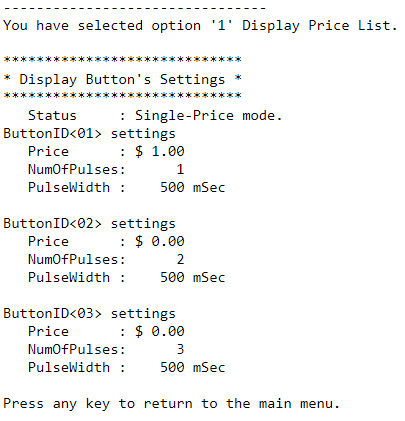
This default set the MDB to Pulse converter in a Single-Price mode at $1. It is a default single action interaction from your customer. When a card payment is made, the board will automatically collect $1 from your customer and then automatically activate your machine.
Single-Price mode is enabled when only one price is set, while the rest remain at $0.00. If all the button is set as $0.00, ButtonID<01> will be the default button that will be activated by the payment action.
To configure this board with your own settings, you will need to prepare the following,
- a USB-C cable (with USB type-A to type-C connector)
- a computer/laptop/mobile phone/tablet
- a serial terminal software
For further detailed guide on configuring the PIC-031 MDB to Pulse board, please click here.
For ordering more than one board, you can click on the “Add to cart” instead.
We also have an add-on user-interface board that supports up to 16 buttons (16 price). You can purchase your own push button with light indicator to connect. We can also custom touch buttons panel with light indicators as your machine user-interface.
This board is designed for use with most of the machines that can accept pulse input. For customisation of this board to cater for your machine and use-case, you can contact our sales engineer for further support.