Written by Lim Siong Boon, last dated 06-Jul-08.

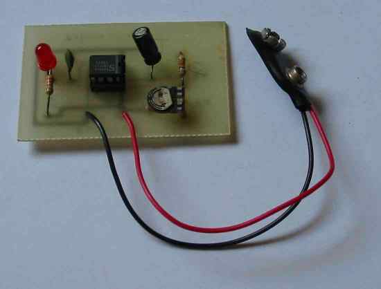 |
I had this chance to visit Singapore Polytechnic on their open house during my secondary school days. From what I recall, this is the 1st electronic PCB project I ever build. It is a basic LED blinker. The blinking rate can be adjusted with the variable resistor on board. I had build a working circuit without knowing much about electronics at that time. |
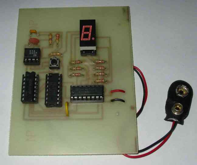 |
This is a electronic dice circuit board. Basically it will generate a random number 1 to 6 when the push button is pressed. I couldn’t remember how I got this circuit. |
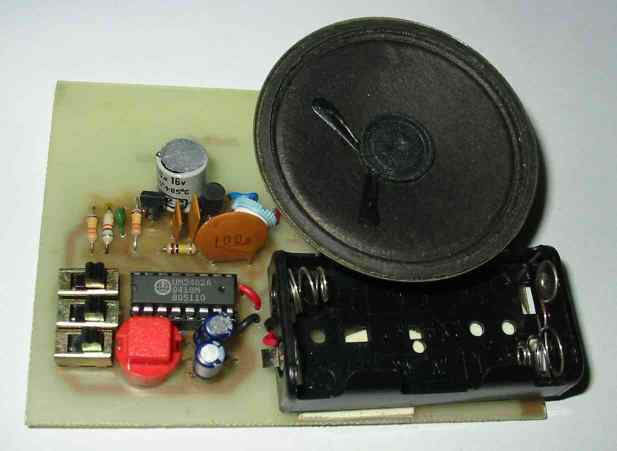 |
My first electronic audio project build during
my first semester course “Diploma in Electronics, Computer and
Communication” in Singapore Polytechnic. It is call a Melody Generator.
Basically the IC contains a number of music tune. Passive component and
transistor amplifier are interfaced to the IC to generate the music. The
switches is for selecting operation mode, while the red push button is to
activate the function. As you can see, the PCB board is quite large, but I manage to squeeze the circuit traces onto a quarter of the board space. We start off with component purchase, PCB board routing design, PCB board fabrication, soldering up to troubleshooting in this project. My first taste of a full electronic project run through. |
|
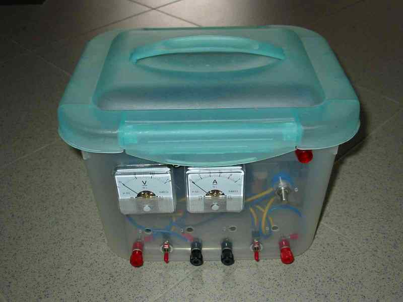
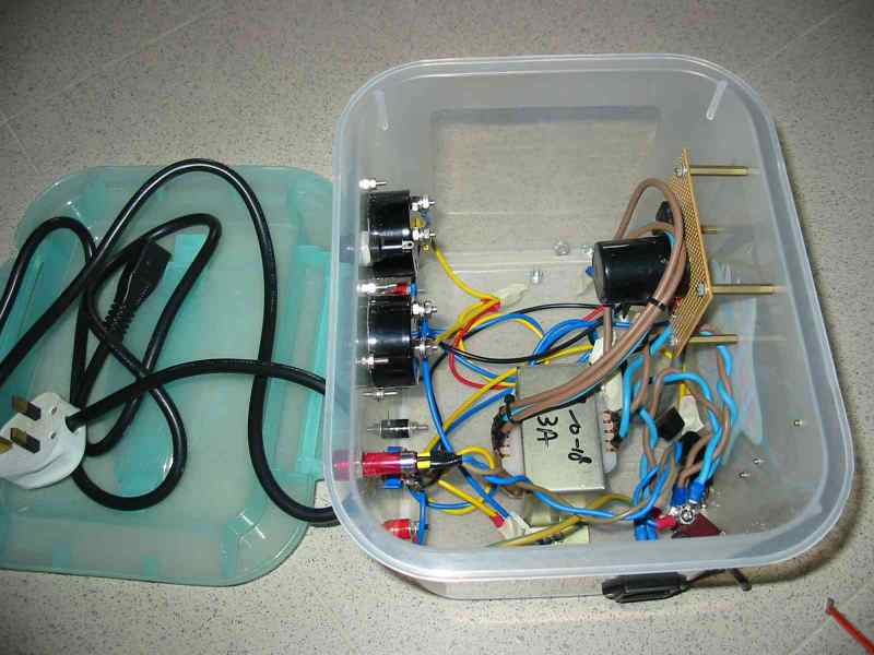
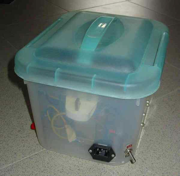
My first home build power supply. 15Vdc 1A rating. I have been trying to
look out for high current power supply circuit with current limit function,
but failed to find one good one. All component are rather cheap except the
voltage and current meter which is about S$10 each.
|
|
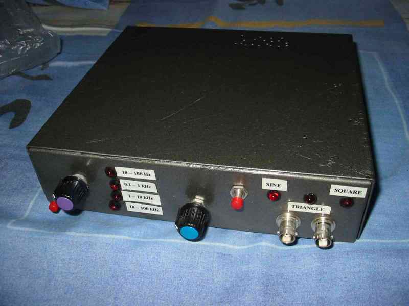
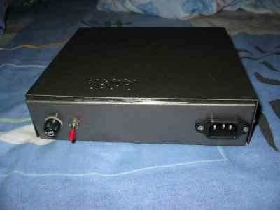
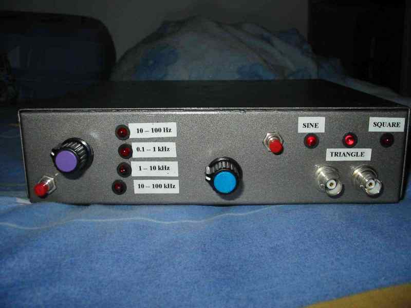
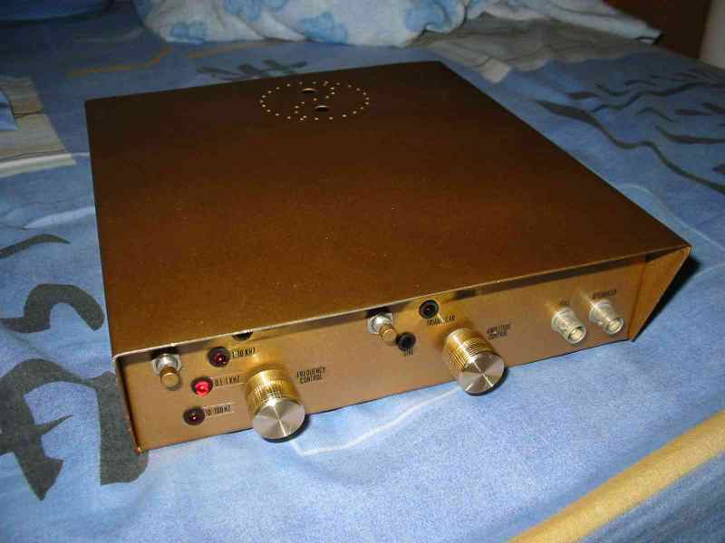
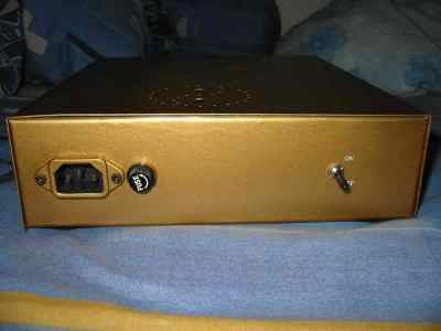
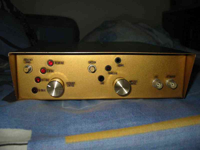
This a signal / function generator I build during my second year in my diploma
course.
|
The function generator can generate sin, square and triangle signal for
system testing. It is power by a signal generator IC, while the rest of the
component on the PCB interface to the IC. For this project, we are involve
in more engineering process from Computer Aided Design for the PCB layout,
PCB fabrication, component purchase, chassis design and fabrication,
soldering and troubleshooting.
My brother’s work. He is also study in electronics.
|
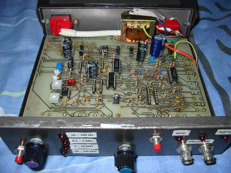
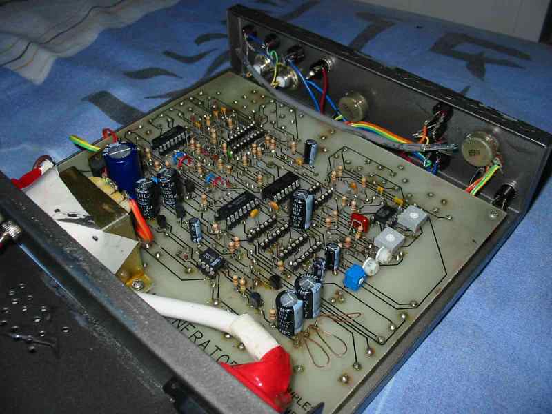
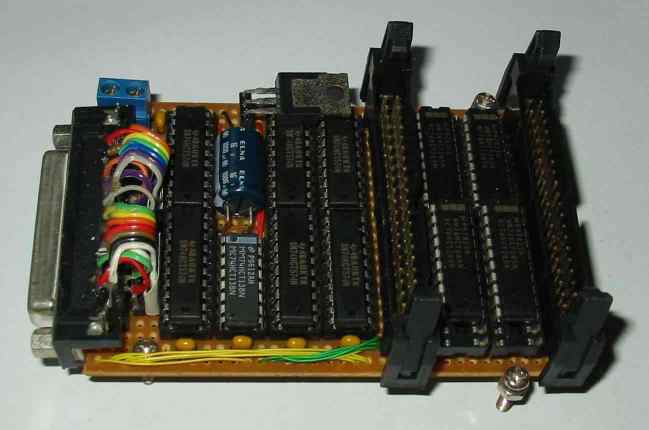
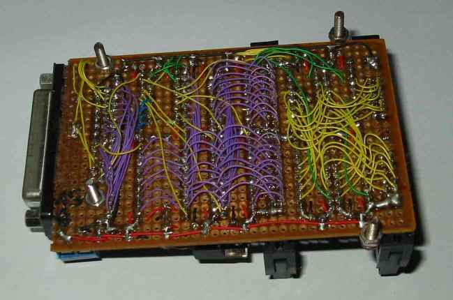
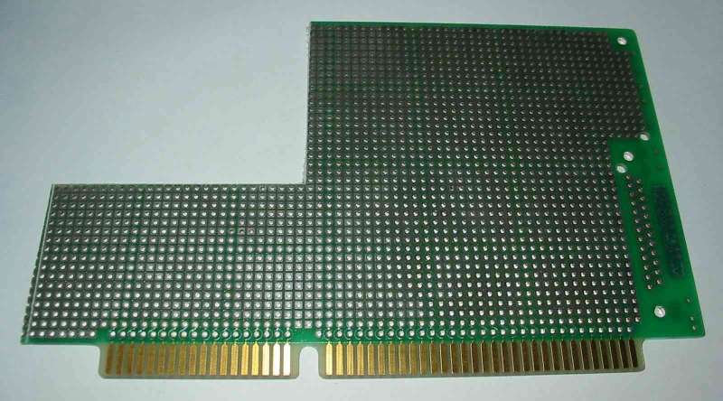
Component side
Wiring side. |
Parallel port, Input/Output I/O interface
board. This multiplex I/O interface is control through the parallel through
a computer. The circuit uses the IC
74HC245 (bi-directional octal bus
transceiver buffer),
74HC138 (active low, 3 to 8 line decoder demultiplexer) &
74HC574 (octal d-type latch flip flop, positive edge
trigger) to multiple the 8 bits port into 32 bits port. The circuit is taken from a electronic cook book, “101
Circuits”. It is one of my first few home build project that I have done. I managed to squeeze all component onto the PCB board. As seen from the photos, there is hardly any space between the components. The wiring side is very dense, as there is almost a wire soldered to each pad on the board. Quite proud of myself for this achievement. |
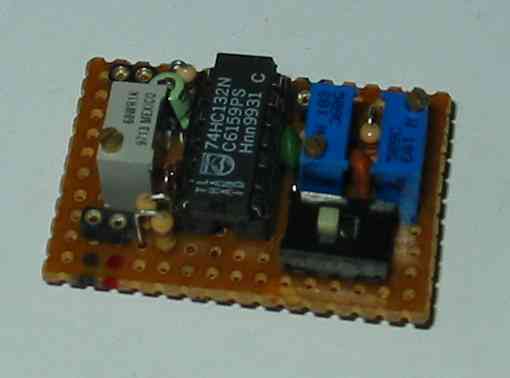 |
This is suppose to be a inductor measurement circuit. The circuit uses logic gates to generate frequency for the inductor measurement. By reading the dc output voltage, we should be able to tell the inductance of the component. I didn’t really do much test to check if it is working well. |
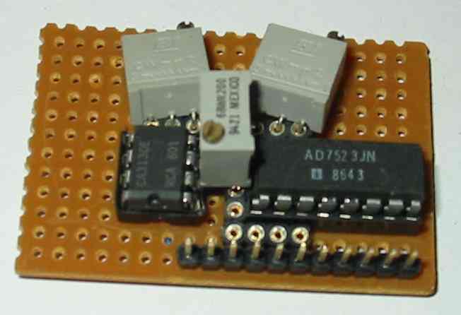 |
test circuit 1. |
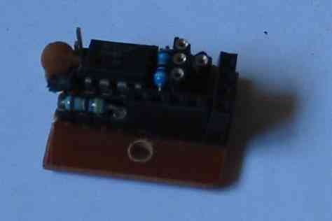 |
test circuit 2. |
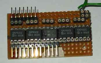 |
Op amp test circuit. |
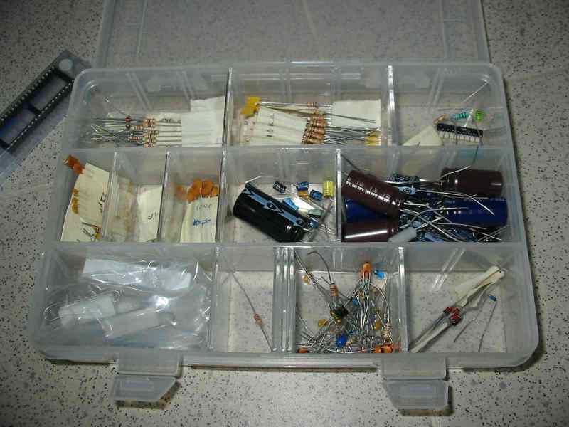 |
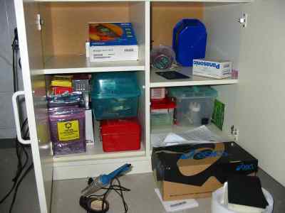
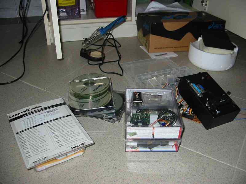
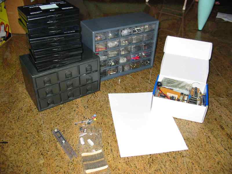
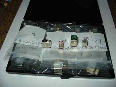
I am still sourcing for an affordable storage system for my components. Any suggestion? |
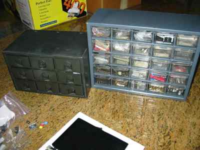
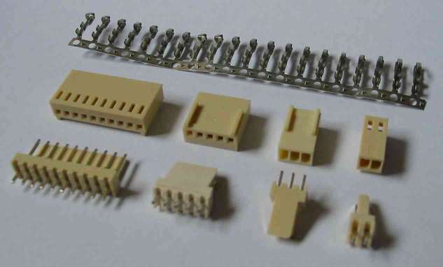
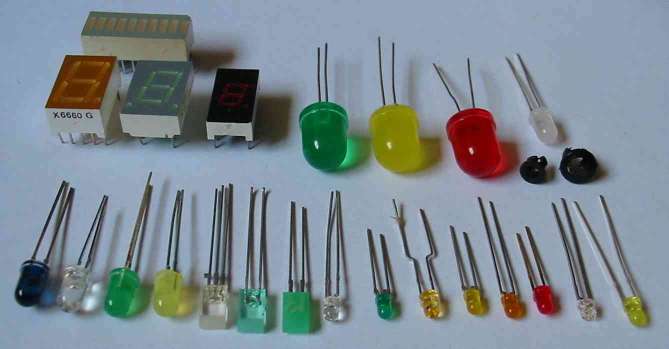
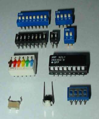
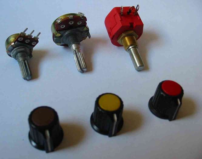
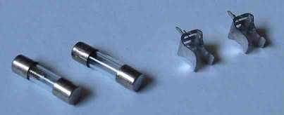
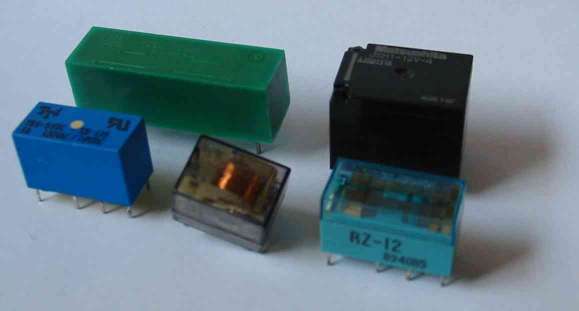
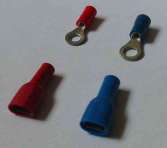
Basic Components for Electronic Circuit Project
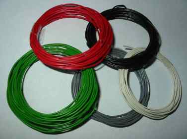
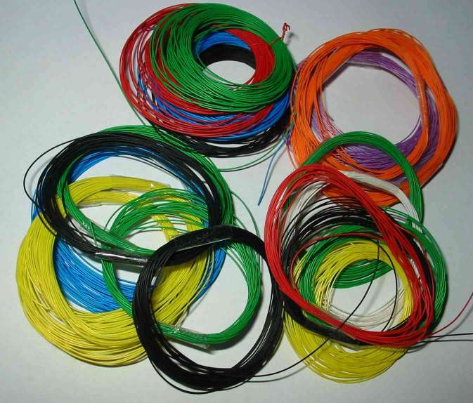
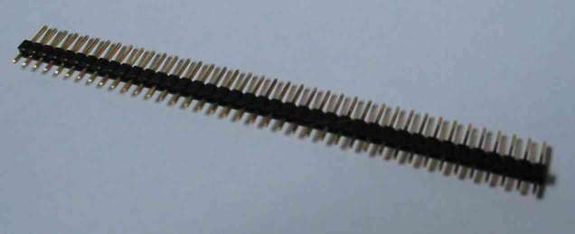
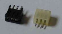
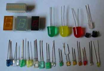
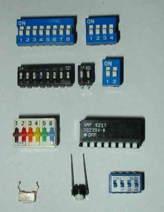
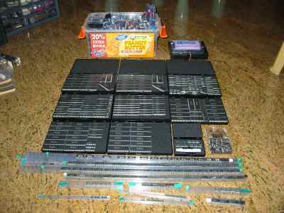
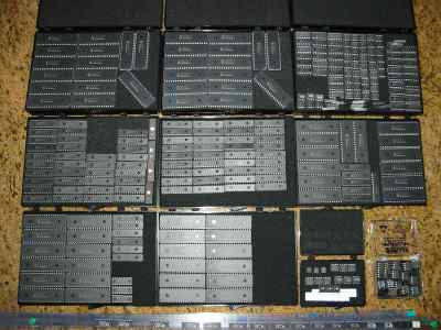
More Components
![]()
![]()
by Lim Siong Boon