Telephony Communication
DTMF decoder using MT8870DE.
A telephone controlled device interface.
DTMF decoder using MT8870DE.
A telephone controlled device interface.
Written by Lim Siong Boon, last dated 06-Jul-08.
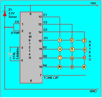
This circuit detects the dial tone from a telephone line and decodes the keypad pressed on the remote telephone. The dial tone we heard when we pick up the phone set is call Dual Tone Multi-Frequency, DTMF in short. The name was given because the tone that we heard over the phone is actually make up of two distinct frequency tone, hence the name dual tone. The DTMF tone is a form of one way communication between the dialer and the telephone exchange. A complete communication consist of the tone generator and the tone decoder. In this article, we are use the IC MT8870DE, the main component to decode the input dial tone to 5 digital output. These digital bits can be interface to a computer or microcontroller for further application (eg. remote control, phone line transfer operation, etc…). |
|
| Keypad Dial Tone Frequency Table
|
Kit Research History In the early days, our phone system used to be operated by human operator in a telephone exchange room. The caller will pick up the phone, giving instruction to the operator to connect their line to the destination over the other end of the telephone. As more and more people find phone technology a useful communication tools, line connection use human operator has become a tedious task. As technology matures, pulse/dial tone method was inverted for telephony communication. It uses electronics and computer to assist in the phone line connection. Basically on the caller side, it is a dial tone generator. When a key is being pressed on the matrix keypad, it generate a unique tone consisting of two audible tone frequency. For example, if the key ‘1’ is being press on the phone, the tone you hear is actually consist of a 697hz & 1209hz sine signal. Pressing key ‘9’ will generate the tone form by 852hz & 1477hz. The frequency use in the dial tone system is of audible range suitable for transmission over the telephone cable. On the telephone exchange side, it has a decoder circuit to decode the tone to digital code. For example, the tone of 941hz + 1336hz will be decoded as binary ‘1010’ as the output. This digital output will be read in by a computer, which will then act as a operator to connect the caller’s telephone line to the designated phone line. The telephone exchange center will generate a high voltage signal to the receiving telephone, so as to ring the telephone bell, to notified the receiving user that there is an incoming call. This project article focus on a simple DTMF (dual tone multi-frequency) decoder circuit. This circuit can be interface to a computer, allowing caller to computer interaction. Many communication application can be build for example, a computerize call receiving/diverting phone network system. Remote control to Home/Office electrical appliances using a telephone network. DTMF is a popular project especially in DSP (digital signal processing) subject. DSP software algorithm can be implement to generate as well as to decode DTMF tone. It is very interesting, and I will try to cover that aspect in near future. For now we do the hardware way. |
|||||||||||||||||||||||||
Singapore Customized, custom made Electronics Circuits & Kits
|
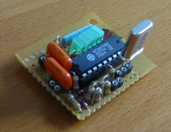
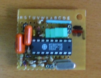
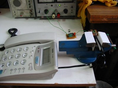
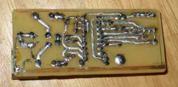
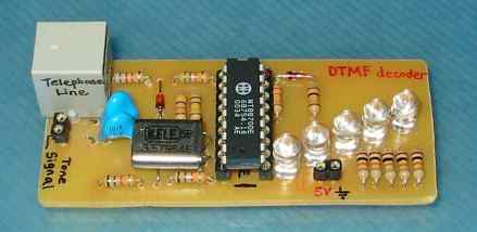
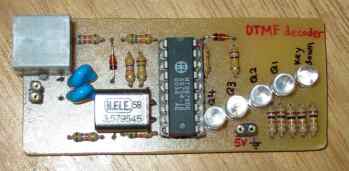
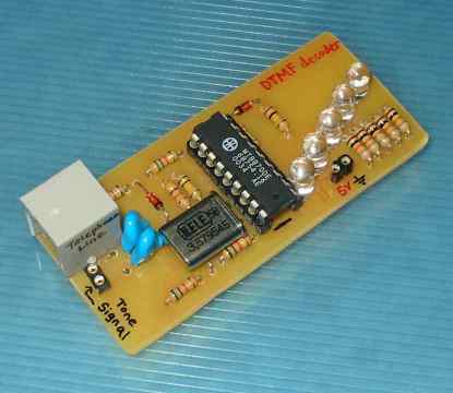
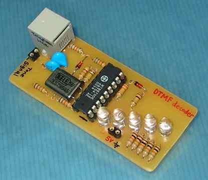
Photos of DTMF circuit built. |
DTMF
Circuits This the first DTMF circuit I build. Very small, roughly about my thumb size.
|
|||||||||||||||||||||||||||||||||||||||||||||||||||||||||||||||||||||||||||||||||||||||||
|
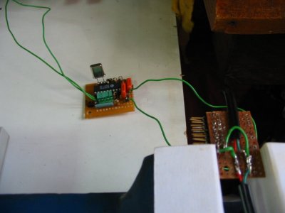
Output Logic behavior from the DTMF decoder IC.
TOE: Logic 0 Q4: Logic 0 Q3: Logic 0 Q2: Logic 0 Q1: Logic 0
TOE: Logic 1 Q4: Logic 0 Q3: Logic 0 Q2: Logic 0 Q1: Logic 1
TOE: Logic 0 Q4: Logic 0 Q3: Logic 0 Q2: Logic 0 Q1: Logic 1
TOE: Logic 1 Q4: Logic 0 Q3: Logic 0 Q2: Logic 1 Q1: Logic 0
TOE: Logic 0 Q4: Logic 0 Q3: Logic 0 Q2: Logic 1 Q1: Logic 0
TOE: Logic 1 Q4: Logic 1 Q3: Logic 0 Q2: Logic 1 Q1: Logic 0 |
Detection of dial tones is
reflected on the bit TOE, while the output Q4, Q3, Q2, Q1 indicate the dial
tone that is being detected on the telephony system. A complete table of the
decoded digital output for individual dial tone is available in the coming
section.
These are the decoder output table for the given dial tone detected. Notice that there are key tone for A B C and D. These are special tone which are normally not found on our telephone. It is a common standard build into the decoder chip. The circuit is relatively simple and straight forward, and all components can be easily found. Schematics and BOM is provided below for your reference.
|
|||||||||||||||||||||||||||||||||||||||||||||||||||||||||||||||||||||||||||||||||||||||||
Schematics (Click on the picture for enlarge view) |
||||||||||||||||||||||||||||||||||||||||||||||||||||||||||||||||||||||||||||||||||||||||||
 Component Layout (Silkscreen) |
 PCB Bottom Layer (PCB trace) |
|||||||||||||||||||||||||||||||||||||||||||||||||||||||||||||||||||||||||||||||||||||||||
|
|
Bill of Material (BOM)
|
|||||||||||||||||||||||||||||||||||||||||||||||||||||||||||||||||||||||||||||||||||||||||
 no button
press
no button
press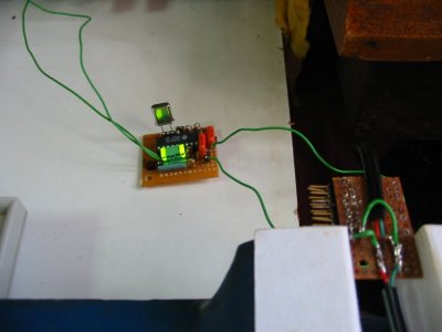 ‘1’ press
and hold
‘1’ press
and hold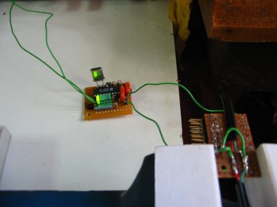 release
from button ‘1’
release
from button ‘1’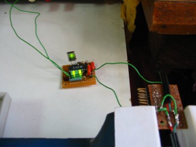 ‘2’ press
and hold
‘2’ press
and hold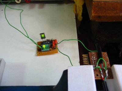 release
from button ‘2’
release
from button ‘2’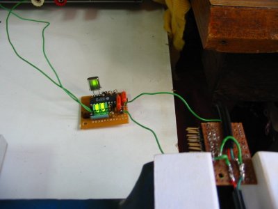 ‘0’ press
and hold
‘0’ press
and hold
Singapore Customized, custom made Electronics Circuits & Kits
|
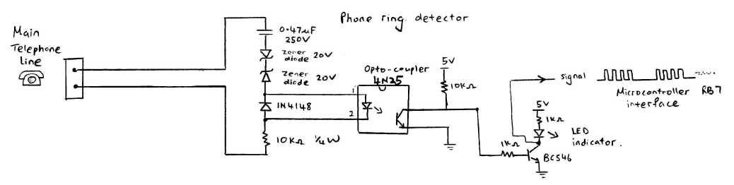
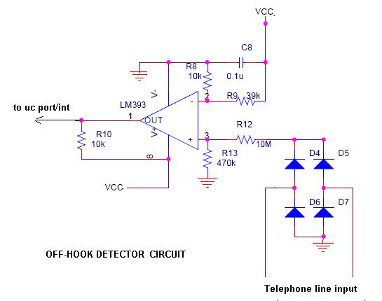
Telephone Ring Detector Circuit Interface to Microcontroller |
|
 |
|
Other DTMF Tone Generator or dialer, NTE1690, TCM5589N, TP5089N (NEETRON Sim Lim Tower #B1), 5088, 4089 (YH Radio Sim Lim Tower #B1), LC7366
Other DTMF Tone Decoder 8870, SSI-202, LC7385, KT3170 (alternative to 8870 from YH Radio Basement 1 simlim)
Other DTMF Tone Generator + Decoder, 8888, 8889, 8880, HT9170C
| Other Circuit References | |
 |
 |
 |
 |
 |
 |
circuit7-LS1240, ringer.pdf |
|

Keyword: circuit detects dial tone, telephone line, decodes keypad remote telephone, Dual Tone Multi-Frequency, DTMF, two distinct frequency tone, communication, remote control, tone generator, tone decoder, IC MT8870DE, digital output, interface computer microcontroller, Telephone Ring detector.