1. CommunicationCommunication is essential in electronics system. It can be in the form of wired or wireless, serial or parallel. The main idea is to transfer information from one system to another system. Communication in one direction is call a simplex communication system, and duplex means communication is in both direction at the same time. Half duplex means that communication is taking place in both direction but only one direction communication is taking place at any one time.Communication takes place when the information that are sent is able to be understand by the receiving device. The receiving side must be able to interpret what message the sender is trying to tell. Communication between electronics devices usually deals with logic 1s and 0s. A high pitch sound may indicate a logic 1, while a low pitch tone may representation logic 0. With the receiving device having this common understanding, it will be able to understand what information the transmitting device is trying to convey. Beside using tone as the mean of signaling, the medium can be in other varying form for example, frequency, voltage, color, smell, wavelength, etc… A typical electronic system uses the concept of voltage or frequency. The choice of signal varies. Voltage/frequency changes can be produced and detected using simple electronics, so it is relative a easier type of signal to implement. The information from the sender can be in the form of voltage. By detecting the voltage, the receiving device is able to interpret the information. The common understanding or interpretation of both the sending and receiving device is known as the communication protocol. The information conversion to a suitable transmission signal is also known as encoding. Decoding is the other way round. There are more complex choice of signal transmission but we will not touch on those area.
In today’s wired communication system, there are a wide variety of serial communication standard from RS232, RS485, USB, CAN, and many more. They are simply the standard defined for communication hardware. It is the hardware setup for the transmission of signals, define as the physical layer. Physical layer deals with the choice of signaling in order for communication to take place. It can be voltage level or frequency as mention earlier. The speaker and the ear in the diagram can be interpret as a physical layer for transmitting the information. Without this physical layer, sound cannot be produce or received.
Some idea of wireless communication.This traffic system is trying to send information to you by signaling green yellow red colored light using visual means.If you can understand the information that the hand is trying to show you, wireless communication is taking place.
Sound transmission through air medium is another example of wireless communication.
The examples above illustrate a simplex system, where message is convey in one direction. Information travel from one system to another, but not the other way round. Ear is not meant to produce sound while speaker are not design to listen. This illustrate a simplex system.
Some form of wired communication.
Telephone network (Duplex)
This is a simple simplex system illustration. The left side is the switch system, which consist of a mechanical switch moving up and down. The state of the switch can be easily recognize by the bulb system on the right. The switch movement is communicated to the bulb which will lights up. The communication medium is the pair of transmission wire. This simple circuit demonstration how wire can be use for communication purpose.
Transmission of information using 0V and 5V is simple, but it can represent only 2 state (or 2 distinct information). Not much information can be convey using signal with only 2 state. There is also a limit to the number of voltage level allowed. Defining more discrete voltage level can represent more information but the signal on the receiving side could be easy misinterpret due to noise and attenuation. A new dimension of representing more data can be in the form of time multiplexing. By coding a signal in sequence, more information can be send. A 0V followed by a 5V may represent ‘A’. 5V followed by 0V may represent ‘B’, 5V followed by another 5V may represent ‘C’ and so on. The size of information that can be transmitted is going to be endless. This form of signal representation in sequence is used in serial communication. It is the most commonly use communication method adopted by various standard USB, RS232, RS485, Ethernet, etc.Communication using logic 1 and 0 is quite simple but seems far away from the information system we have today. In handle such a complex information, the data is actually encoded further and further to a higher protocol level. This will keep the forming of information simple and easily managed from various level. It is like printing dots to form alphabet, arranging alphabets to form word, forming up words to become a sentence, and forming sentences to tell a story. The information will be getting more and more meaningful.
Protocol is just like a common language that system uses to understand the data. A Chinese language has a totally different protocol from an English language. Until we learned the protocol, communication will still not be possible although human have the same speech capability (our speech capability can be thought as the physical layer). Although Malay language uses the same alphabet “A to Z” as in English alphabets, the higher forming protocol is still quite different.In the world of electronics voltages or frequency defines the logic, forming a sequence of logics to form a data byte. These string of byte consisting of typical 8 bits, may represent data or control character. With these common understanding between the two system in place, application will be able to communicate with one another.
In today’s complex communication, protocol can be interpret in terms of layers namely physical layer, data link layer, network layer, transport layer, session layer, presentation layer, application layer. You may like to read up other website for more information on this communication model.
Communication layer is a very abstract theory, when I was first expose to the term. If you are still not clear on data layer, the best thing is to hands-on and built a communication system from scratch, sending useful data bit by bit. You will be more aware of how the whole system works and get to understand why data communication people keep on talking about the layer stuff.
In this article, various serial communication interface USART are presented. They are TTL version of the serial communication, represented by 5V / 0V. It is similar to RS232 physical format represented by -/+10V in the voltage.
USART is not design for distance communication. To enable longer communication distance, USART signal will need further encoding into RS232 signal format before transmission. Other common names for USART (Universal Synchronous Asynchronous Receiver Transmitter) are UART or SCI (Serial Communications Interface). Serial data in TTL format is the very basic serial communication interface to understand.
The articles present common solution in communication between USART, RS232, RS485 and USB.
2.Understanding USART & RS232
USART stands for Universal Synchronous Asynchronous Receiver/Transmitter. It is simply a form of serial data communication.USART is very common, and a clear understanding can easily lead you to other form of interfaces. The following article will present the interfaces from USART to RS232, RS485 and USB.
The article presented focus on the practical aspect of USART and RS232. For technical details, I would strongly recommend the following website from beyond logic,
Microcontroller and PC communication using RS232RS232 is the encoded version of USART. The encoded signal allows the data to be deployed for longer communication distance. Some article may have define a maximum communication distance of 15m for RS232 signal. You can try pulling the communication distance further, it should still works actually. 15m is only a general guideline.If the data transmission rate is low, the distance can even go further. There have been reports from the internet that some user have achieve 50m to 200m without any problem. For me, I have tried baud rate of 9600bps over 100m without any problem. For baudrate 115000bps over 20m, you might start to encounter transmission error. Baudrate is presented in bps (data bits per second). The higher the value the more the data can be transmitted in a given time period. The higher the speed, the shorter the communication distance.
As what I experience, the data transmission length of the cable can determine by many factors. The factors include the following,
– data transmission speed
– quality of the cable, noise (unwanted signal)
– transmitted voltage
– receiver sensitivity
– etc…
We have to remember that electronics are still analog in nature. Communication distance using RS232 can be increase further if the cable is of better quality, a shield or coaxial cable for example.
The most significant factor is still the data transmission speed. The following is a reference that I found in one website regarding the relationship between data baud rate and cable length.
The transmission cable should be twisted as a pair for your +ve & -ve (or ground/reference signal). The reason for having it twisted is to ensure that the pair of wire is as close to each other as possible. Why? This is because the signal energy (or refer as integrity) is contained between the +ve & -ve wire. Any gap between the two wire can result in signal distortion (losses). The gap represent a change in the cable impedance (capacitance/inductance) affecting the signal integrity on the wire. Electromagnetic, it is about how the field interact with one between the gap.
I had once wiring up two RS232 communication line without using twisted wire. In order to save the trouble to lay another set of cable, I tried to squeeze the two RS232 line to the cable. It end up with a lot of communication problem. The data I send on com1 is able to trigger the devices connected to com2. The signal on com1 is actually coupled over to com2, causing com2 to think that some data is being received. The data is the corrupted version of the data from com1.
The higher the frequency, the worst is gets. This is also why our network CAT5e CAT6 cable are all twisted inside, protected by aluminum foil shield. No sharp bending should be allow, as this will cause the twisted pair to open up a gap in between. A typical cable bending radius as specify in the manufacturer datasheet is about 25-50cm. All this details comes into the picture when your communication speed is high. I see many contractor laying the network cable without any of these consideration. The effect is negligible, for low speed communication. Most of us might not even realized it too, because minor transmission error is already resolved through the TCP/IP protocol. A coaxial cable is a better form of cable structure to contain the integrity of the signal. The energy is contain on the dielectric, between the inner conductor core and the outer wire mesh.
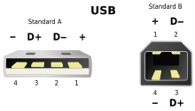
RS232 Connection
Pin
Function
1
Carrier
2
Rx
3
Tx
4
DTR
5
Gnd
6
DSR
7
RTS
8
CTS
9
Ring
DB9 male socket on DTE (data terminal equipment), example: a computer.
Pin
Function
1
Carrier
2
Tx
3
Rx
4
DTR
5
Gnd
6
DCR
7
CTS
8
RTS
9
Ring
DB9 female plug on DCE (data communication equipment), example: a modem.
Pin
Function
1
DSR
2
Carrier
3
DTR
4
SG
5
Rx
6
Tx
7
CTS
8
RTS
RS-232D is defined as RS232 being terminated with the RJ45 plug. They are used on cisco network switch equipment for command control input, and also on RS232 to Ethernet server for Lantronix products. The advantage of RJ45 compare to DB9 is the size. More ports can be connected to the equipment with a much smaller panel interface.
Going back to our RS232…..
Loop Back RS232 Connector
– Short Pin 2 to Pin 3 (if no hardware control)
– see the following diagram, Loop Back Plug (for hardware control RS232 communication)
The loop back connector is useful in troubleshooting communication problem. Data being sent out to the line is being echo back to the equipment, indicating that the communication connection is working fine. It also indicates that the equipment communication is working.The loop back can be deploy on the various point within the communication line to pin point any communication fault due to equipment or communication line.
Null Modem(show picture of a null modem cable, data being transmitted from one direction to another)
Note: Input pin 11, 13 can be left unconnected. There is a internal pull-up resistor, pulling pin 11 to 5V and pin 13 to 0V
The physical communication standard defines the signal voltage of -10V for logic ‘1’, and +10V for logic ‘0’. However in practise, the voltage can be ranging from +/-3V to +/-25V. Not to worry if the measured voltage is not +/-10V. Typical receiver is able detect the incoming signal with voltage as low as +/-3V.A microcontroller like PIC16F877a uses USART (5V system). The PC (personal computer) that we have in the office/home uses the standard RS232. To enable a microcontroller to communicate with the computer, a RS232 to TTL converter is required.
IC chip maker has come up with the integrated circuit for interfacing RS232 with TTL logic (5V for logic 1, 0V for logic 0), making the interfacing work very simple. MAX232 is one of the many IC in the market which helps to convert between RS232 -/+10V and TTL +/- 5V. It is a simple voltage level converter in short. The charge pump design allows the circuit to generate +/-10V from a 5V supply, with the help from the four capacitor. With charge pump to double up the supply voltage for RS232 transmitter, there is no need to design a power supply for +/-10V.
The diagram on the left shows the schematic of the MAX232 IC circuit. It consist of only 4x 1uF 16V electrolytic capacitor, and the MAX232 IC itself. It is that simple. I have include a layout which I always use for PC to PIC16F877a microcontroller, RS232 interface.
MAX232 alternative: LTC1386
MAX232 (3.3V version): MAX3232
Coming article,- How to test the communication line.
Virtual Serial Ports Emulator.zip (ETERLOGIC.COM) emulator allows you to Connector – create a virtual com port which can be opened twice. Allows two application program to communicate to each other via the same serial port number. Data Splitter – create a virtual com port which allows multiple application to share a single existing com port. Pair – Create 2x new virtual com port which is cross connected to each other. (A null cable). Allows two application program to communicate with each other. Mapper – Remap a physical com port to another com port number. Useful for old software which does not allow com port number to be changed. TcpServer – convert a physical com port to a TCP port as a server, so that multiple client can be connected and access to the physical com port. TcpClient – convert a physical com port to a TCP port as a client. If connection is lost, this client will auto reconnect to the server. Serial Redirector – connects up between to com port. (A null cable) UDP Manager – convert a physical com port to a UDP port as a server, so that multiple client can be connected and access to the physical com port. Bridge – Connects up two data stream. Spy – VSPE device to spy on a data stream.Other Software Tools – BillSerialMonitor.zip
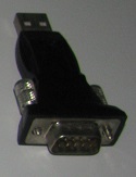
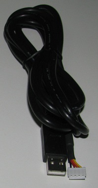
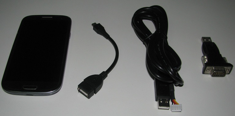
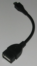
Using Andriod phone as a terminal to test out serial communication. Andriod mobile device, OTG, USB to UART, USB to RS232OTG cable A OTG cable is required to connect the USB to UART or RS232 device.
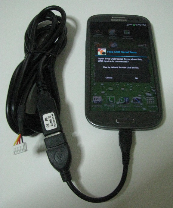
Not all USB to UART, or USB to RS232 converter can be used with Andriod device. This is due to the built in driver available.As of 27 Mar 2014, these are some of the USB to Serial converter chipset that can be used with the Andriod devices. PL2303HXD, PL2303EA, PL2303RA, PL2303SA, FT312D, FT311D (PL230 3HXA and PL2303XA are not supported)
Using a free andriod apps “USB Serial Terminal Lite”.
Once the OTG and USB to UART converter is plugged to the andriod device, the andriod will automatic detect and attempt to launch the “USB Serial Terminal Lite” apps.Click on the icon phone, to make a connect to the USB-UART device. There should be no error when it is connected, and the phone icon will turned into a ‘X’ icon.To test if the USB UART is working properly, make a loop back connection by shorting the Tx and Rx pin. This loop back means that whatever data you send will be return to the device as data being received. Your device is able to receive what it sent out. This loop back test is important. It indicate that the device is able to send out data, and is also able to receive data. For USB to RS232, short pin 2 and pin 3.
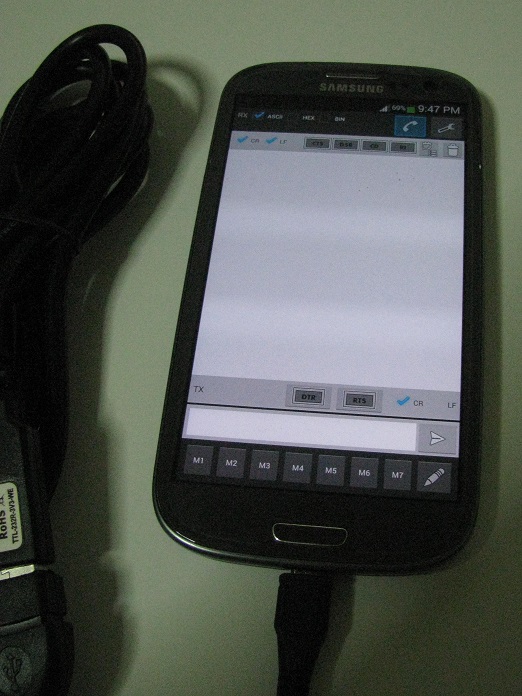
Click onto the text field on the bottom of the apps. Key in and ascii data, and click on the send button on the right (logo of an arrow pointing right). Immediately after you click on the send button, you should be able to see on the display screen, the same text that you have sent. If you disconnect the loop back connection, you will not be able to see the text that you have sent.
This apps is good. It can display the data in hex, which is used very often in hardware development work. There are also memory which allows you to save frequet sent data.
Microcontroller interface using RS485 & RS422After a period of research, I found out that RS485 and RS422 is in fact the same.RS422 is a duplex configuration. RS422 using 4 wire to communicate in both direction. One pair of wire to do transmit and the other pair to receive. Both sides is able to transmit and receive at the same time.
RS485 is a half duplex configuration. RS485 using only 2 wire to communicate in both direction. With only two wire, it means that when one side is transmitting, the other side of the communication line will be receiving. Both side cannot be transmitting at the same time. For RS485 transceiver, use MAX485 or MAX3485. They have the same pin out except that MAX485 uses 5V supply, MAX3485 uses 3.3V supply.
RS422 can be connected to work with RS485 to either receive or transmit date, but not both. RS422 can be wired directly using a pair of wire, +ve to +ve, -ve to -ve terminal. For RS422 transceiver, use MAX488 or MAX3488. They have the same pin out except that MAX488 uses 5V supply, MAX3488 uses 3.3V supply.
MAX485 pin
Alternative pin label
Terminal A (+)
Y, TX+, RX+, TX1, RX1
Terminal B (-)
Z, TX-, RX-, TX2, RX2
for
Part no.
Volt
Speed (Kbps)
RS485
MAX485
5V
RS485
LTC1480
5V
RS485
SN65HVD10
5V
RS485
SN65HVD11
5V
RS485
SN65HVD12
5V
RS485
SN75HVD10
5V
RS485
SN75HVD11
5V
RS485
SN75HVD12
5V
RS485
SN75176
5V
RS485
ST485
5V
RS485
SP481
5V
RS485
SP483
5V
250
RS485
SP483
5V
RS485
SP485
5V
RS485
DS75176
5V
RS485
SP1485
5V
RS485
SN65HVD3082
5V
200
RS485
SN65HVD3085
5V
1000
RS485
SN65HVD3088
5V
20000
RS485
SP3082
5V
115
RS485
SP3085
5V
500
RS485
SP3088
5V
20000
RS485
DS3695
5V
RS485
DS3696
5V
RS485
MAX3485
3.3V
1200
RS485
MAX3483
3.3V
250
RS485
MAX3486
3.3V
2500
RS485
SP3494
3.3V
RS485
LTC1480
3.3V
RS485
ST3485
3.3V
12000
RS485
ISL3072
3.3V
250
RS485
ISL3075
3.3V
500
RS485
ISL3078
3.3V
16000
RS485
ISL3172
3.3V
250
RS485
ISL3175
3.3V
500
RS485
ISL3178
3.3V
20000
RS485
ISL83483
3.3V
250
RS485
ISL83485
3.3V
10000
RS485
ADM3493 (Diff from SP3493)
3.3V
250
RS422
MAX488
5V
RS422
SP490CN-L
5V
RS422
SP3081
5V
115
RS422
SP3084
5V
500
RS422
SP3087
5V
20000
RS422
LTC490
5V
2500
RS422
SN75179
5V
RS422
DS8921
5V swapped pin5,6
RS422
UA9638C
5V swapped pin5,6
20000
RS422
MAX3488
3.3V
250
RS422
MAX3490
3.3V
12000
RS422
SP3071
3.3V
RS422
SP3490
3.3V
10000
RS422
SP3493 (Diff from ADM3493)
3.3V
RS422
ADM3071
3.3V
250
RS422
ADM3074
3.3V
500
RS422
ADM3077
3.3V
16000
RS422
ADM3493
3.3V
RS422
ADM3488
3.3V
250
RS422
ADM3490
3.3V
10000
RS422
ISL3171
3.3V
250
RS422
ISL3174
3.3V
500
RS422
ISL3177
3.3V
20000
RS422
ISL83488
250
RS422
ISL83490
10000
RS422
SN65HVD30
3.3V
26000
RS422
SN65HVD31
3.3V
5000
RS422
SN65HVD32
3.3V
1000
check out and update for MAX3491 MAX3490 MAX3076 MAX3077 MAX3073 MAX3074 MAX3070 MAX3071
MAX488 alternative (pin8+,pin7-pin6+,pin5-,5V, version):
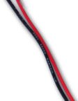
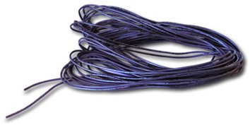
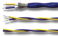
twisted pair wire (with shielding)
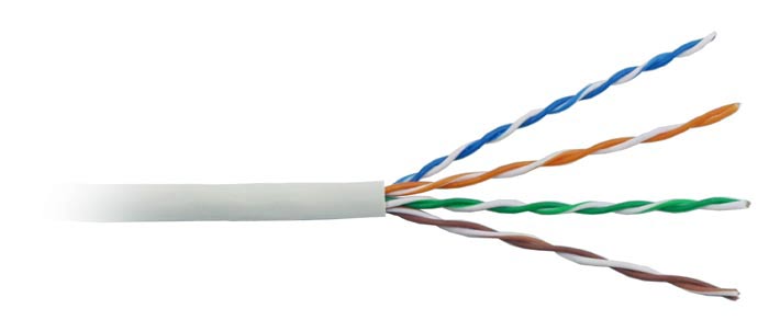
twisted pair wire (without any shielding)
Notice the gap between a normal pair of wires. By twisting the cable, the gap can be reduce, therefore minimizing the interference.
Unlike RS232 signal, RS485 implements differential voltage as the physical signal to communication. More information on the physical RS485 signal is illustrated in the next section. The cable for RS485 or RS422 works as a pair to transmit and another pair to receive. This is important, because it means that the cable need to work as a pair in order to transmit the signal properly. Proper type of cable is required.
The picture on left is a twisted pair wire. It is recommended to use twisted pair cable to transmit RS485/RS422 signal. The reason being twisted wire can help minimize the gap between the 2 wire, therefore minimizing interference and signal distortion. This can be explain through the electromagnetic theory. The gap or loop between the two wire actually acts as the antenna intercepting nearby signal, as well as coupling it’s own signal to wire next to it. These results in distortion in the signal, and ultimately reduces the data rate you can transmit over the wire pair. The twisted cable also maintain a distance, make it difficult for another wire to slip in between the wire pair. For further immunity against interference, the twisted pair is wrapped with aluminum foil acting as a shield.
Note that you should deploy twisted pair on a signal wire pair. You can consider one wire as signal while the other one as reference or ground. If the twisted group of wires contains more than one signal, it will make the interference worst.
Attempting to twist the bunch of wires for RS232 will not improve the performance. The wires for transmit (TX) and receive (RX) will interfere. It is possible that you might receive some rubbish data immediately after you perform a data transmit. This problem will be more obvious when you send the data at very high baud rate and longer wiring distance, eg 115.2kps at 20 meters. It is due to the signal on the TX wire being coupled onto the RX wire, triggering the device, thinking that there are incoming data on the opposite line.
For RS232, you might like to twist between TX(pin 3)/ Gnd(pin 5), and another twisted pair RX(pin 2)/Gnd(pin 5) to improve the transmission. There is only a common pin, therefore the two wire will have to share the pin 5 ground.
RS485 opto coupled interface circuit
4. RS232 & RS485 signal analysis
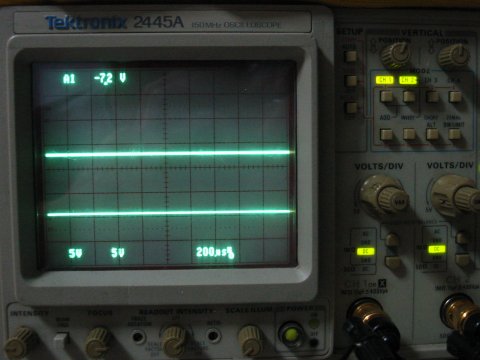
RS485 and RS232 signal analysis experiment setup. The computer serial com port is connected to a RS232 to RS485 converter device. Both RS232 and RS485 is then monitored on the oscilloscope.Unlike digital scope or logic analyzer, analyzing inconsistence communication signal on an analog oscilloscope can be difficult. To assist the scope in displaying the data signal, the data is being send to the com port repeatedly. This periodic signal enables the scope to display the signal clearly on the screen.Adjust the triggering and the hold time to position the full data byte transmission on the screen. You can learn more about using oscilloscope from this ebook “XYZs of Oscilloscopes” from Tektronix website.
The signal level from the output of MAX485 IC depends on the load from the communication line. Typically the open circuit output of the MAX485 IC with/without a 120Ω termination resistor has ?V1 = 5Vdc, ?V0 = 0.8Vdc. When the line includes the inline resistors and the pull down/up resistor for the RS485 bus, ?V1 = 3.2Vdc, ?V0 = 0.6Vdc. These open circuit reading is taken from the output of MAX485 IC using an oscilloscope. Some note is observed when attempt to watch the RS485 communication from the oscilloscope. When the probe get into contact with the signal, the communication fails. The receiver device is able to decode the signal. It is believe that the ground reference of the probe might be connected to earth and will affect RS485 signal
The picture on the left shows the data byte 0x33 or ascii char ‘3’ being transmitted on the communication line. The signal starts from the left to the right. The signal begins with a start bit (logic 0), lowest significant bit (LSB), follow on to the highest significant bit (MSB), and ends with the stop bit. The binary form of the data transmitted is as follows.
START
bit0
bit1
bit2
bit3
bit4
bit5
bit6
bit7
STOP
0
1
1
0
0
1
1
0
0
0
The baud rate setting is set at 9600bps, data bits of 8, no parity bit, 1 stop bit.
The top display the actual RS232 signal from a computer system’s serial com port. This signal is tapped from the TX (+ve connected) and ground line (-ve connected). It has loaded input from the converter device. The higher voltage level represents logic 0 at about 6Vdc, while the lower voltage level is a logic 1 at about -7Vdc. When there is no transmission, the signal idle at -7Vdc.
The bottom display the RS485 differential signal converted from the RS232 signal using a converter SNA10A. This signal is tapped from the A (+ve connected) and B terminal (-ve connected). This is an open load signal from the output of the converter device. The higher voltage level represents logic 1 at about +4Vdc, while the lower voltage level represents logic 0 at about -4Vdc. When there is no transmission, the signal idle at about 1V.
The picture on the left shows the voltage level of both signal when idling. Idling refers to the state where no data is present on the communication line.The top display the idling signal level from the RS232. The idling signal is at -7Vdc level (logic 1).The bottom display the idling signal level from the RS485. The idling signal is at about +1Vdc level.
The picture on the left shows the oscilloscope ground reference signal level. This reference snap shot, is a reference for comparison with the snap shot taken above. Both signal display the reference of 0Vdc.The top display the ground reference signal level from the RS232.The bottom display the ground reference signal level from the RS485.
If you are interested in the binary level on Ethernet standard. Here is some basic information on the low level or hardware aspect Ethernet from Analog Devices.- 2008-04-00 A Beginner Guide to Ethernet.pdf
The Ethernet looks very remote to me when I first try to understand it. It is very complex. After a few years of experience, I slowly gain enough confident to talk about this type of communication.
In fact, Ethernet is another form of serial communication. The hardware aspect is similar to RS485, with pin 1 & 2 handling the transmission of the serial data, while pin 3 & 6 is for the receiving of serial data. I have not find any concrete information, but I imagine it closely to a RS422. One pair of wire for TX, the another pair for RX. The physical signal for RS422 is the same as RS485. The signal are interchangeable. RS422 is a duplex while RS485 is a half duplex communication line (see above for further information).
The beautiful part of Ethernet is on the streaming bytes riding on the serial communication line. This stream of bytes is also define as the data packets or protocol. It is the data protocol that make Ethernet so special. Which is why there is so little information on the physical aspect on the Ethernet. Ethernet is all about protocol. Protocol consist of the data and the header. The header contains the MAC, IP, PORT and other information which will helps the data packet to be routed to the correct destination. You can imagine a letter to be delivered. Letter contains address which helps the post man to deliver the letter.
What we typical see on the cover of a letter:
Att: David
myCompany Pte Lte (business registration number J123456789)
Street 3, Blk 3, #03-33.
myCompany denote the company name which can be quite unique. You can imagine the MAC address as the company name or as a business registration number. The MAC address is a set of number (6 bytes, 0x11 0xAA 0x22 0xBB 0x99 0xFF) which uniquely identify the electronics hardware Ethernet device. It is the basic number the hardware will have, which identify itself from the rest from other gadgets. Most computer have at least one network card/adaptor. Each card is a unique communication device, and therefore have it’s own MAC address. If a PC has 3 network card installed, it would have 3 different MAC address. MAC address is the 6 bytes ID of the Ethernet hardware.
Next comes the IP address. You can think of it as your home address. The number for IPv4 (IP version 4) is 4 bytes long (192.168.1.255). Unlike a MAC address, IP address can be configured by the user/programmer. You can imagine that while the company name remains no change, no matter where it shifted it’s address. IP address can be changed. Like a letter, the IP address will allows your data packet to be delivered to the correct place. Each Ethernet hardware (network card) will have it’s own MAC address. Each MAC address will be assigned the IP address. Your company will be identified by it’s unique number and the location address. A typical computer installed with 1 Ethernet card, can be identified with it’s MAC and IP address.
PORT is quite tricky to me at first. What is exactly a port. You can relate it to the name of the person on our letter example. The letter may be delivered to the correct address, but it does not indicate who should receive the letter. Port identify the person that should receive the data packet. In our computer example PORT is a number which defines the application software that receive the data. When you open up your web browser, the browser software will open it’s port number 80. Any incoming data packet indicating port 80, will be passed to the browser software. The browser software will then render the data onto the screen for you to read. Similarly other network application works in this way. Some common application’s protocol and it’s port number are as follows,
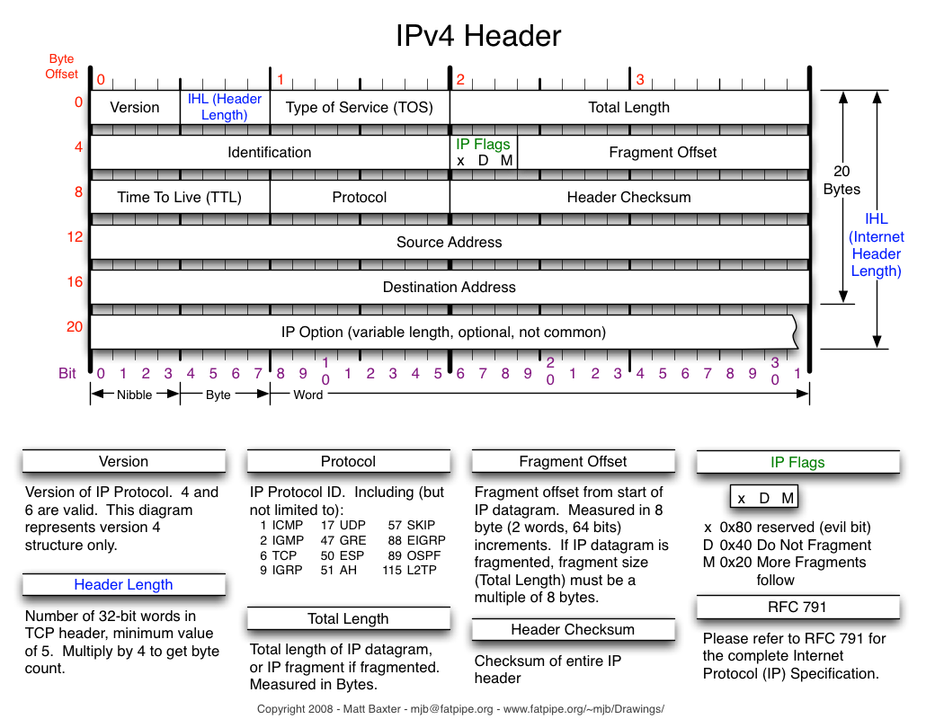
Protocol in details.IPv4 (Internet Protocol version 4)
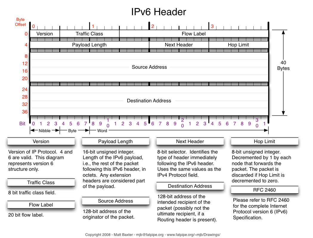
IPv6 (Internet Protocol version 6)
TCP (TCP Transmission Control Protocol)
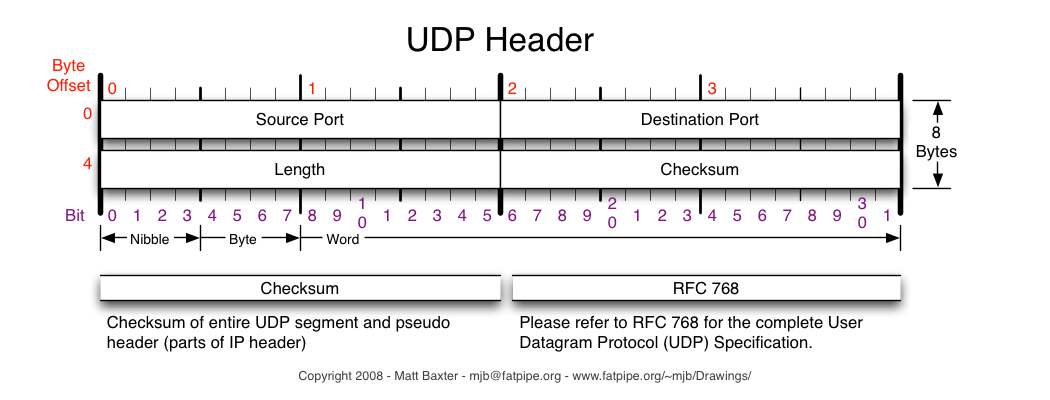
UDP (User Datagram Protocol)
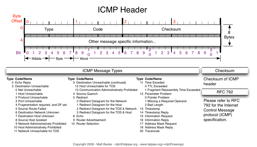
ICMP (Internet Control Message Protocol)
My complete understanding about port, actually started off from it’s strange name “port”. At that time, I cannot visualize what is exactly a port. I started to think about its name. Why people call it a port. While writing article on RS232 com port, my mind suddenly opens up. I am convinced today that, the word port comes from our old computer parallel/serial port. It is a revolution of data communication.I started to imagine wildly with any references. Imagine in olden days where Ethernet is not known yet, people used serial/parallel port for communication. Each application occupy a port, which is the current situation with serial and parallel port. You cannot have two software application using the same port number. If there are more application that needs to communicate, you can imagine that the computer will need a lot of RS232 port at the back. Each and every port is being occupied by the respective software for communication. Many cable as we can imagine. That will be quite a headache. The Ethernet consolidate these physical communication lines into just only one. In order for the application to identify their own data, the port number is implemented into the data header/protocol. The port number actually acts as a virtual port for the computer, and will route the packets to the correct software application. Now all packets communicate through the same physical Ethernet cable. A bit of imagination will helps a lot in understanding the topic.
The data packet route to the correct IP address, after which it will check if it arrive to the correct MAC ID. When the packet reaches into the computer, the packet is further route to the port, where the appropriate application software will read and further interpret the data packet.
Ethernet has more features, but the basic concept is still as easy to understand as a RS232 serial communication.
What we have discuss so far is only the protocol on IPv4 header. Protocol or header is just bytes of information that describe about the data it carries. The data itself may also contains its own header which interpret another data within. It is like layers and layers of onion skin. Just as you peel off the header for the data, you notice another header to peel. Layer after layer, we finally got our data.
The first layer is IPv4 (still quite common in this era dated: July 2009) or IPv6 header (new protocol).
Going deeper, we have another layer typically TCP or UDP. They defines the manner, the data is being exchanged across the communication channel. TCP/IP protocol means that the data is transported using the IP and TCP header. Two layer actually.
After so much theory, let’s talk more physical stuff on Ethernet. As shown on the bottom and left, these are the typical wiring on the network. Straight cable between the network equipment and PC, and also cross cable between PC to PC or equipment to equipment.
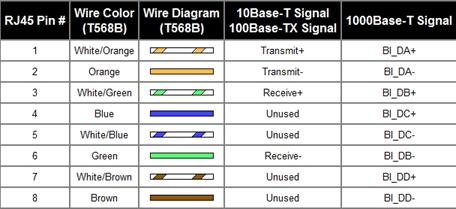
Ethernet Pin Out from your computer device
Pin no.
Color
Description
1
Orange
/White
TX+
2
Orange
TX-
3
Green
/White
RX+
4
Blue
—
5
Blue
/White
—
6
Green
RX-
7
Brown
/White
—
8
Brown
—
I have been looking for hours a confirmation on the network pin 1 & 2 (TX±). Whether the pin out is referring to a DTE (a computer) or DCE (network switch/hub). Most website indicates the TX RX pin out scheme, but did not indicate whether the description is for a DTE or DCE. After searching for so long, I finally found it.
I would like to give credit to this website for providing the information.
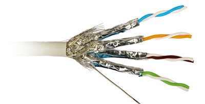
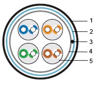
Notice that a network cable contains 4 pair of twisted cable, and the pair is differentiated by the 4 sets of color pair. If you remember the RS485 wiring as mention in the earlier section, these twisted wire will look very familiar to you again. The twisted wire provides a better protection against possible interference. Notice how the twisted pair is assigned to the RX signal± and the other pair assigned to TX signal±.
There are many type of cat cable to choose from. Depending on your deployment need, these are some of the selection that you may have to consider.
– CAT5e, CAT6a, CAT7, CAT8
– FTP, SSTP/SFTP, STP/USTP, UTP
– Solid or Stranded wire core
– Indoor or Outdoor
– AWG wire size
Some people may refer the network cable as RJ45, which is not correct. RJ45 is actually the name of the plug. Another name for the plug is 8P8C connectors.
The twisted pair cabling standard is refer as the CAT standard. The term is typically being referred to when selecting the type of network cable. The CAT define the signal frequency that the cable is able to carry for a distance of 100m. High frequency signal gets filter away as the cable becomes longer, which also means that the data rate will be reduced. This means that a short CAT5e cable is able to transmit as fast as a longer CAT7 cable. Therefore 100m is a normalize distance to compare between the cable quality.
Standard
Max Frequency
CAT7a
1000Mhz
CAT7
600Mhz
CAT6a
500Mhz
CAT5e
100Mhz
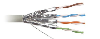
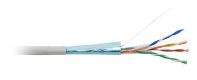
Some network cable comes with aluminum foil shielding to protect the signal from external noise interference. FTP cable have a single foil covering the 4 twisted pair. STP call for a foil shielding for each twisted pair inside the cable, improving interference from adjacent twisted pair. SSTP is similar to STP with an extra foil around the 4 twisted pair, creating a double foil shielding. Unshielded cable is indicated by UTP.
The cable may also comes with either a solid or stranded for the core of the wire. Solid core is typically suitable for permanent deployment where it is unlikely that the cable position would be changed. Stranded version is suitable for patching purposes, where the cable get to be used or bend more frequently. Stranded cable is more robust then a solid core version for patching use.
Network cable also comes in a more rugged packaging for outdoor use. The protective cable skin is tougher and the cable core may be reinforced with a backbone that protects the cable from being crush by heavy weight.
The AWG (America wire gauge) specify the size of the copper wire core. Bigger AWG number denote a smaller cross section area, though lower current than a smaller AWG cable. Network cable has AWG ranged from AWG 22 to 24.
Coaxial cable is a much better structure than a twisted pair configuration. Coaxial cable can carrying a much higher frequency due to it’s structure carrying signal in transverse electric magnetic (TEM) mode. The cable is however bulky, heavy and more costly as compare to a twisted pair alternative.
USB is getting popular replacing RS232 in the consumer market. However the use of serial communication is much more popular in the industry because it is much simpler to deploy and troubleshoot. In the view of this, conversion between USB, RS232 and USART is certainly an advantage in bringing products into the consumer market in the fastest possible time.
The presented interface uses the IC FT232BM to interface between a USB from the computer and USART which is used in a microcontroller. From the computer and microcontroller point of view, it is the same old serial communication that are discussed previously.
USB is that simple. This is possible with the help of the IC FT232BM from FTDI Chip. The IC and it’s virtual com port driver has transform the conversion from USB to USART almost invisible. With the driver installed into the PC, it acts as a bridge which transforms the USB hardware into a virtual serial com port. The computer software will transmit the data to the virtual com port as what it will do when sending data through a normal Com1 Com2 port. The virtual com port will be run by the FTDI USB driver which will communicate through USB communication to it’s IC FT232BM. The manufacturer has also provide IC control through a *.dll direct driver, a alternative solution to the virtual com port driver. For further information, you may like to visit their website.
Alternative there is a even more integrated USB to UART solution from Silicon Laboratories. IC CP2102 is much more simpler, with no external components. It is an attractive solution, however I have not try it before.
The circuit present the hardware conversion between the USB and USART using FT232BM. The circuit can be implemented on top of existing USART electronics, so that USB bus can be used, for serial communication with the PC.
– ST7540 FSK powerline transceiver (AN2451), from ST
9. SPI
not available yet
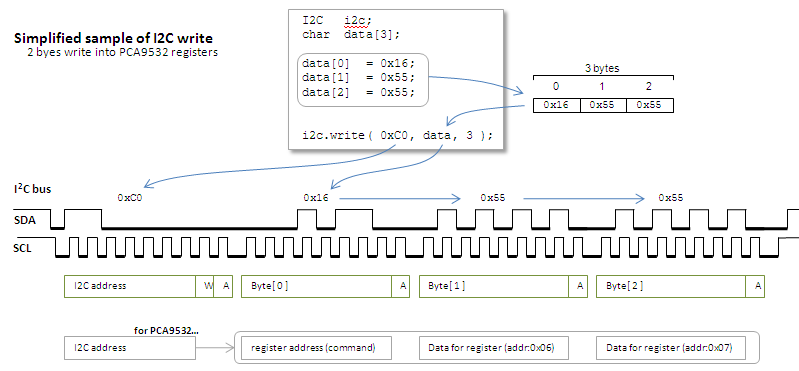
10. I2C
I2C is a 2 wire, simplex communication physical protocol. It is usually used in the inter IC chip communication, like SPI.I2C uses only 2 wire and is able to send and receive data. The data transfer rate is slower compare to SPI. The protocol is much more complex than SPI, which is why troubleshooting I2C is not simple. The protocol consist of many header signal for protocol control. It is those header that makes the decoding tedious with using a i2c logic analyser instrument.
Once you got the hang out of it, it is fairly managable.
The following signal shows communication between a microcontroller (master) and IC MCP79410 (slave), using bit banging method.The yellow signal is SCL, clock line. The blue signal is SDA, data line.
The command/data that was sent to MCP79410 are as follows (Write data to EEPROM), – start – 0xAE (write command to MCP79410) – 0x00 (address for the following data) – 0xAA (data to be written into the address) – end
1- START signal. SCL is held high when SDA perform a negative edge signal (logic high to low).
2- Logic 1 is sent. The SDA is loaded with logic 1 just before SCL is clock positive edge.
SDA signal/data line should remain stable during the HIGH period of the clock pulse. Any changes during the HIGH clock pulse duration are inteprested as control signals (START or STOP command).
3- Logic 0 is sent. (at the +ve edge of SCL) 4- Logic 1 is sent. 5- Logic 0 is sent. 6- Logic 1 is sent. 7- Logic 1 is sent. 8- Logic 1 is sent. 9- Logic 0 is sent. 10- The SDA and SCL lines are release at this moment in time. SCL returns to logic high, but SDA is still at logic low even when both lines are release. This shows that the slave device is actually holding the SDA line down. The holding of this SDA line is the slave acknowledging the data received. This is important because it shows that the slave is responsing to the command send. The slave is working. The SDA line is release shortly.
Program hang when executing a read command.
Problem was resolved. The microcontroller was able to read the data properly from MCP79410.
The command/data that was sent to MCP79410 are as follows (Write data to EEPROM), – start – 0xAE (write command to MCP79410) – 0x00 (address for the following data read) – start – 0xAF (read command to MCP79410) – read byte(data to be written into the address) – endThe signal stop while executing the read byte function. Further investigation shows that there was a coding problem with the I/O port. The program was expecting a logic but it didn’t happened. The reason for the hang.
After resolving the problem, the micrcontroller was able to read from MCP79410 successfully.
*** Very useful tips summary in intepreting the I2C signal
1) Any changes in data logic on the SDA signal must be done when the SCL signal is low. SDA data sampling will take place when SCL is positive edge.
2) SDA signal change (positive or negative edge trigger) while the SCL signal is high will be intepreted as command (START, STOP, RESTART).
3)START or RESTART command happens when SDA is negative edge while SCL is at logic high. STOP happens when SDA is positive edge while SCL is at logic high.
4) To issue RESTART, set both the SDA and SCL line to idling state without issuing a STOP (meaning release SDA first then SCL). Then issue a START. This START command is a RESTART command.
Simple notes to Troubleshooting I2C:
1) Perform a write process, and take note of the Data line, to ensure that the I2C device is responsing. If it is not responsing, it could be that the IC is not properly soldered, or it could be damaged (unlikely).
2) Ensure that the minimum clock duration is met. Typical clock high should be of a minimum of 0.6us, and the clock low should have a minimum of 1.3us. Check the signal waveform to ensure that this condition fulfil.
Tips
The pulling down of the SDA line is ACK, meaning the slave I2C device has responsed to the request.
ACK is also triggered by master if master still wants to read more data from the slave. This is reading with ACK. If this is the last byte to be read. It will be read with NACK.
 This traffic system is
 green yellow red colored light using visual
 If you can understand the
 Sound transmission


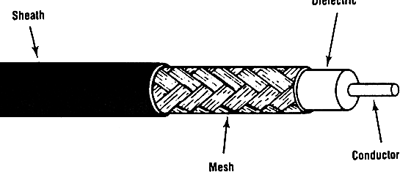 Coaxial