Written by Lim Siong Boon, last dated 08-Dec-09.
Click on the picture to enlarge the Schematic. |
DC Motor
Driver using L6203
L6203 a H-bridge driver for dc motor control. It can drive up to a 4A rating motor. There is very few external component, and it is easy to implement. For high current driving from 1A to 4A, it is advisable to mount a heat sink to prevent overheating to the IC L6203. Speed control can be achieve by various duty cycle control signal. In robotic maneuver speed control is necessary to accelerate and de-accelerate the robot. If there is no speed control, the robot can easily skid or experience slow acceleration. The schematic consist of 3 dc motor driver for Spotronic use. Two driver for left/right wheel’s motor, and the third one is for camera rotation motor. |
Click on the picture to enlarge the Schematic. |
DC Motor
Driver using Relay
DC motor control using relay is very simple compare to using transistor. It can drive very high current rating motor (depending on the relay current rating). However the relay is mechanical driven contact (produce sound), and can wear out over time. There is not much control, only clockwise, anti-clockwise and
stop. |
Stepper Motor Controller/Driver Selection
| Stepper Motor IC |
Volt Range |
Internal Mosfet |
Interface |
Thernal Shutdown |
Micro Stepping |
Rds(on) |
Package |
Price |
Comments |
| L6228 |
8-52V |
2.8A (peak), 1.4A |
Logic |
Yes |
No |
0.73Ω | PowerDIP24, PowerSO36, SO24 |
S$10-S$12 |
|
| DRV8825 (***) |
8.2-45V |
2.5A | Logic | Yes |
Yes |
0.25Ω | HTSSOP (28) |
S$6.03 | Overcurrent protection, fault
detection pin, microstep up to 1/32 |
| A3979 |
35V |
2.5A |
Logic | Yes | Yes | 0.28Ω | TSSOP (28) |
S$7.34 | Cross-current protection |
| A4979 |
50V |
1.5A |
SPI, Logic |
Yes | Yes | 0.50Ω | TSSOP (28) | S$7.88 | Cross-current protection,
diagnostic information |
| A4989 (***) |
12-50V | Ext | Logic | Yes | — |
TSSOP (38) | $5.62 |
Cross-current protection,
current limit |
|
L6207
L298
FULL BRIDGE MOTOR DRIVER
ISL83204A
Stepper Motor Controller
L297
Single FULL BRIDGE DC MOTOR DRIVER
MC33886

Singapore Customized, custom made Electronics Circuits & Kits

Click on the picture to enlarge the Schematic.
|
DC Powered UPS
System
This is a simple DC un-interrupt power system for DC powered device. When there is external power connected, the system will tap power from the external source and charged the internal battery at the same time. When external power is withdraw, the relay will switch over which enables the internal battery to continue supplying power to the device. The capacitor value is chosen, depends on the device. It function as a temporary supply source while the relay switches to another power source. This buffer ensure that there is no sudden dip to the power supply during the transition. If the device consume high power, a higher capacity capacitor should be use. Voltage rating of the capacitor as a guide, should be about 2 times the voltage of the supply. The diode act as a block to prevent activation of the relay by the battery supply source. The current rating of the diode, as a guide should be about 2 times the connected device rating. |
Click on the picture to enlarge the Schematic. |
Signal
Switching Circuit
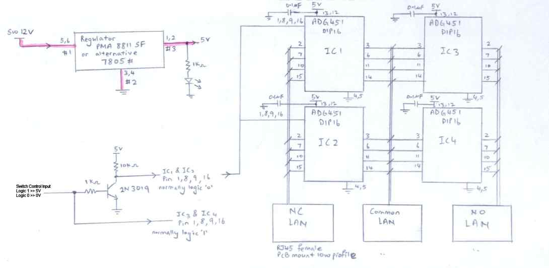
IC ADG451 is an analog switch. It can be used to switch signal on/off or can be configure to act as a signal multiplexer. There are other configuration of analog switch from this series (ADG451 ADG452 ADG453). ADG451 consist of 4 analog switches (active high), while ADG452 consist of 4 analog switches (active low) and ADG453 is a mixture of 2 active high/low. This circuit is designed for switching Ethernet LAN signal. |
Click on the picture to enlarge the Schematic. |
Adjustable PWM
Generator Circuit
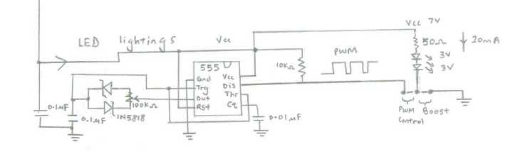
Design Dated: 17 Oct 2006 This is a PWM circuit which generate duty cycle rectangle pulses using the IC 555 timer. The duty cycle is adustable by a potential meter (variable resistor) from 0%-100%. PWM signal can be used to switch on/off power transistor, which can then be use to control Motor speed, LED brightness, controlled power supply, and many more. Vcc power supply to the circuit is 7V for the LED. Power supply range is quite wide for IC 555. The IC can operate with voltage within 5V to 16V. This circuit is designed to control the brightness of LED without the use of transistor to drive. For more information on using transistor to drive high current device, you can refer to project “Switch” at siongboon.com |
 |
Piezo Buzzer
Interface Circuit
Design Dated: 19 Aug 2012 This is a very basic circuit to interface to a piezo buzzer. The input is a PWM rectangular wave driving the sound/tone of the buzzer. Lower frequency result in a lower tone. |
|
Click on the picture to enlarge the Schematic. |
PWM DC Motor Speed/Direction
Control Circuit
Design Dated: 19 Aug 2012 This circuit can control a DC motor forward/reverse. The PWM input control the speeed of the DC motor. |

Click on the picture to enlarge the Schematic. |
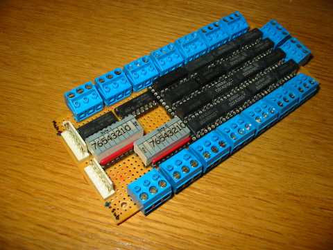
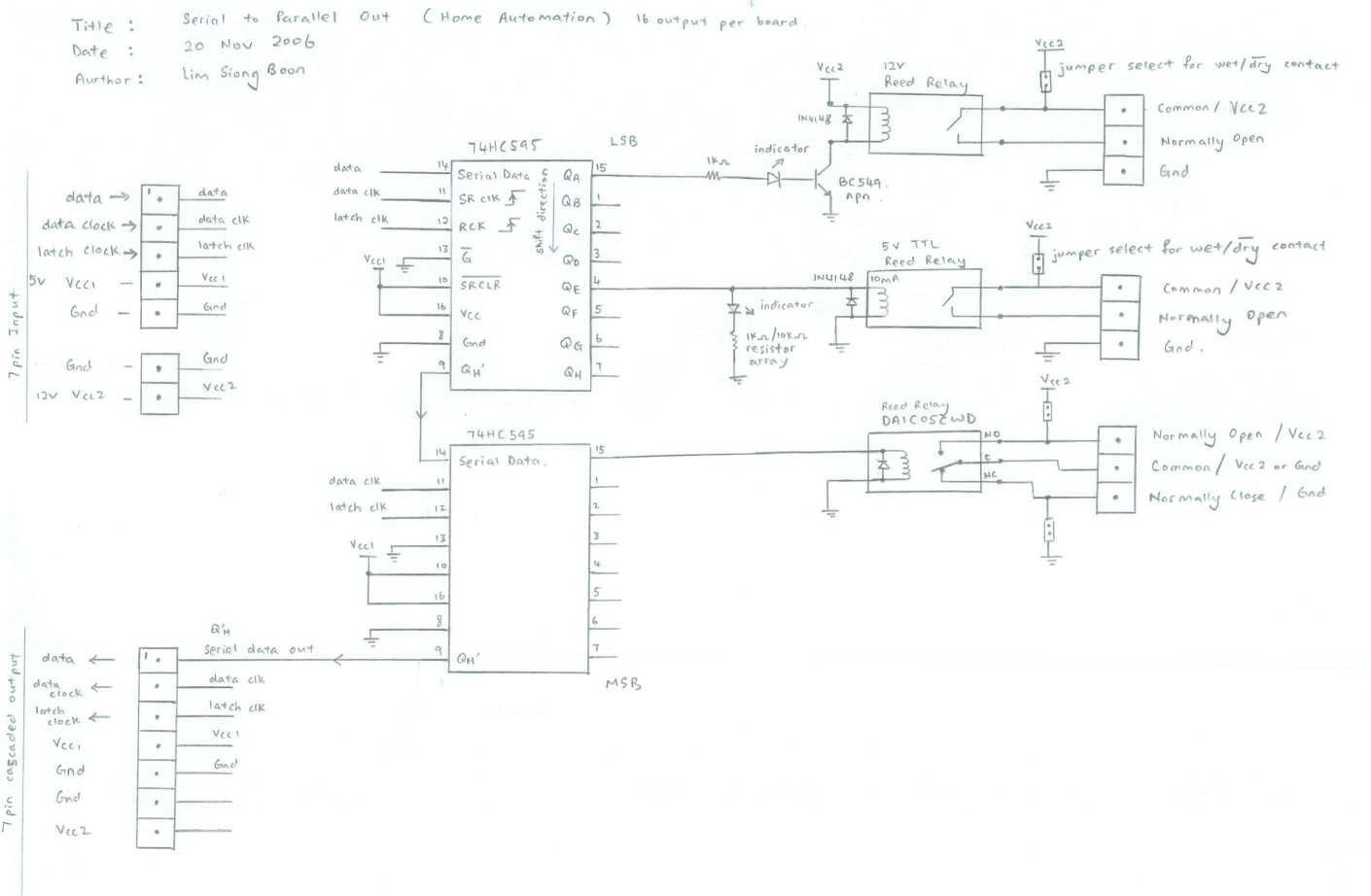
Serial to
Parallel output 16 channel
Design Dated: 20 Nov 2006 This is a serial data input to parallel output circuit. The circuits using 3 signal line, namely the data, data clock and latch clock to send the data to the IC 74HC595. Sometimes more output lines is required for control. With the constraint of limited ports from a microcontroller chip, this circuit comes handy in a project to extend the number of output ports up to infinity. Each 74HC595 IC support 8 bit latched output, which can be cascaded to infinity number of 74HC595 IC, through is able to provide unlimited number of output ports. The trade-off for such a feature, comes with a delay time, and a relative longer firmware coding. If the delay is not of an issue, this circuits can helps to extend the number of output ports, from 3 bit port output. Attached is a function call routine to send the serial data to the circuit’s output. Written for the microcontroller PIC16F877a. ASM source code is here. |

Click on the picture to enlarge the Schematic. |
Parallel to
Serial input 16 channel
Design Dated: 20 Nov 2006 This is a parallel input to serial output circuit. The circuits using 3 signal line, namely the data, data clock and parallel latch enable to read in the parallel data from the IC 74HC166. This circuit comes handy in a project to extend the number of input ports for a microcontroller. Each 74HC166 IC support 8 bit latching parallel input, which can be cascaded to infinity number of 74HC166 IC, through is able to provide unlimited number of input ports similar to the serial to parallel circuit shown above. The trade-off for such a feature, comes with a delay time, and a relative longer firmware coding. If the delay is not of an issue, this circuits can provide the microcontroller with more inputs, from 3 bit port input. Attached is a function call routine to read in data from the circuit’s port to the microcontroller. Written for the microcontroller PIC16F877a. ASM source code is here. |

Click on the picture to enlarge the Schematic. |
2 Channel
Delay Timer
|
Click on the picture to enlarge the Schematic. |
Typical
PIC16F877 Schematic
|
| Various type
of circuit interface (3.3V↔5V)
The schematic illustrate various method of interfacing line between a 3.3V and 5V digital circuits.
The information presented is from, Download full article: 3V Tips ‘n Tricks, 41285A.pdf
Circuit design for interface (3.3V→5V)
|
Interface using commercial available level shifter IC (3.3V→5V)
Circuit design for interface (5V→3.3V)
|

| 12Vdc-230Vac
circuit (100W
) |
 |

Singapore Customized, custom made Electronics Circuits & Kits
by Lim Siong Boon