Don’t be misleaded by my title. I know of many customers being believers
of how the power saver product can help them save on their electricity bill.
This article is NOT about how power saver works, but more about why power saver “Don’t Work”.
To understand how it don’t work, we have
to understand how it works. Understanding Power Saver
Scam in detail.
- Edited by Lim Siong Boon, last dated 24-Jan-2012.
Topic Discussion Overview
|
|
When
I first got to learn about this power saver product during an
exhibition in Singapore, I was a little bit surprise about it. The
meter measuring
the current drop instantly when this power saver thing was turned on.
The surprising part is not about its energy saving performance, but the
fact that business people is really smart. How they are able to make
use of a electrical physics to convince consumer into buying the
product. Example 2: As what I have understood, the power service provider do not charge consumer on the current that we have drawn, but on the real power that we have used up. It will not be fair if they charge us base on the current, because although we might draw higher current, we also returned the unused portion back to the grid. For factory and industrial, the situation is slightly different. They will be charged on the extra current for the reactive load that they have introduce. Why is there such a different? This is because the industrial ususally draw very high current from the grid. If the current is high, the cable to support the high current has to be thicker. If the industrial user do not correct the factor of their manufacturing plant, it will be at the expense of the service provider to lay more cables for them. For industrial user, they will be charged base on the real power and the reactive power that they use. For home consumer, our usage is quite predictable and insignificant. So unless your power meter measure and charges you on both the real and reactive power, you will not need to correct the power factor for your own house. High current uses thicker cable. Cable not thick enough, heat will be generated. This is a form of cable loss. This is also how a safety fuse for electrical system works. The fuse will burn itself if the current is too high. But wouldn’t that means that the cable out from the power station will be very very thick to support the whole population? Yes, but there is another solution. The voltage from the power station is very very high. Given a limited cable size, we can still deliver more power to the population by increasing the voltage. Power is the product of voltage and current. With the limit in cable size, hence the current, we can deliver more power by rising the voltage. That is why you can often see electrical sub-station around the place we live in. It is a big transformer inside which step down the very high voltage to a lower voltage that we can use. There are many stages of sub-station from a power station all the way to the end consumer. You can think of the electrical system as the distribution for our water pipes. High voltage is similar to high pressure for the water pipe. Cable size or current is the water pipe size. Electrical power being the volume of the water. Having a limitation in the waterpipe size does not means that we cannot deliver more water to the population. We can still increase the water pressure so that the water is able to travel faster, hence deliver more water though the pipe out.
1) I have managed to salvage white cylindrical AC capacitor from an office fluorescent lighting using a magnetic ballast. I had remembered seeing such component connected to the setup and have dismantled one for the experiment. It is just an ordinary AC capacitor which electrical contractor sometimes used to correct the power factor of the lighting so that current flowing from the mains supply to the lamp can be minimum. The magnetic ballast is an inductive component. Having this counter balance capacitor load, the power factor can be improve, therefore reduce the current. This capacitor was connected to a 3 pin plug for the experiment. Using a multimeter, I managed to measure the capacitance to be 3.2uF, which is the same value as labelled on the component itself.
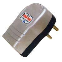
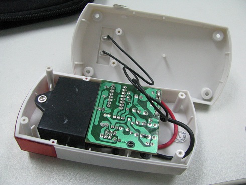
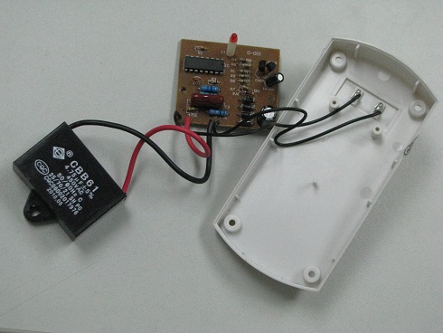
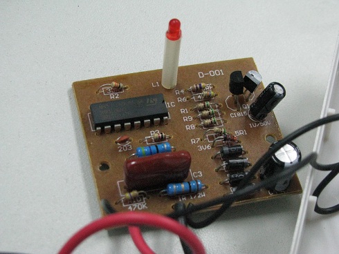
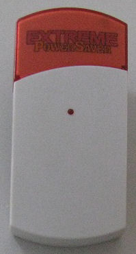
2) GAD1203 Extreme Power Saver (CX005). I have managed to open it up to understand further about it’s interior. The inside consist of a circuit and a black rectangular block. At a glance, it seems quite complicated circuit, but after careful examination, the circuit looks suspicious. The IC chip on-board is a logic gate IC which does not do any function. The black box is actually a 4.75uF capacitor component. The measured capacitance is 5.6uF which is quite close to the label. The incoming 2 pin Live and Neutral is connected parallel to the capacitor and the circuit. Without the circuit, the capacitor will be enough to act as a power factor correcting device.
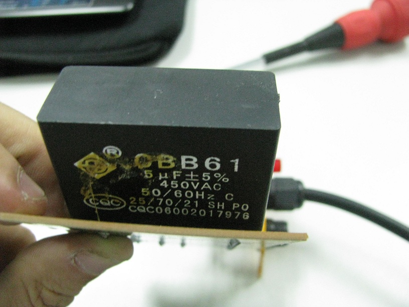
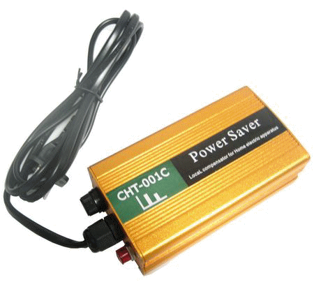
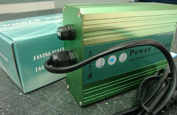
3) GAD1202 Power Saver (CHT-001C), 2400W. This product is easier to do the reverse engineering. It consist of two black box connected in parallel to the AC Live & Neutral wire. The 2 black box is the capacitor measuring 5uF each which is the same as labelled on the component itself. Two capacitor means that the total capacitance is 10uF. There is a lamp indicator which is connected to the AC line, indicating that the device is connected to the AC mains.
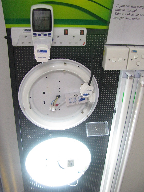
I have this experiment and setup as below with help from saveOne Pte Ltd in Singapore. Their business is mainly in the Asia region Philippines, Thailand, Malaysia and China. This company sells a range of energy saving products, from energy saving lighting, energy saving electronic ballast to energy saving equipments. The picture shows a demonstration rack of their electronic ballast product for circular fluorescent lamp which I have also installed for my house. I like the product and have written an article about it quite some time ago. If you are interested, you can visit this link. The reason I use this rack for the experiment because there was this magnetic ballast fluorescent lamp setup at the bottom of their rack. You can see from the picture, it is the lamp that is lighted up. Magnetic ballast component is an inductive load and is useful for our experiment.
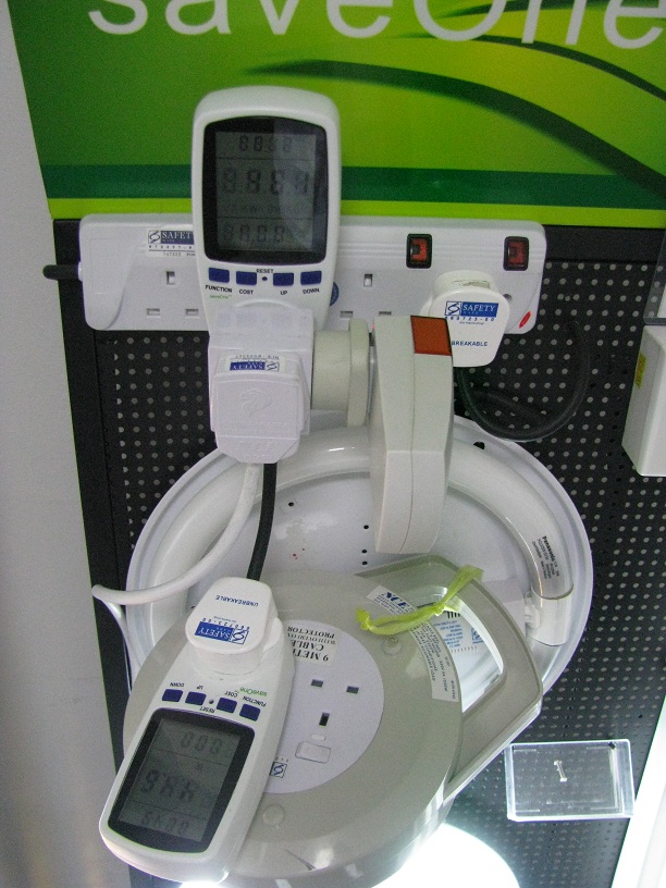
The setup consist of 2x power meter to check on the wattage, current and power factor at 2 location along the power supply line from the mains to the magnetic ballast lamp. Right from the top, you can see a 4 way socket power extension. This is the point where I would tap the power from. The first thing that was connected is the power meter which was connected to the 2nd socket position. This power meter no.1 measures the electricity for the whole setup. The later setup that would be connected to this power meter will be measured. This means that we would be able to know the current flowing from the supply mains to this setup, and also the wattage consumption of the setup. From the power meter no.1, a multi-plug socket was plugged on top of it to split the power outlet into 2. On the right side, it is where the power saver (capacitor under test) will be plugged. The front side is the 3pin plug which is from the cable extension drum. On top of the cable drum is power meter no.2. The magnetic ballast lamp is connected to this power meter no.2. Power meter no.2 measures the wattage, current and power factor for the lamp.
Measure Result from Power Meter no.1
0. Without any thing connected, the magnetic ballast lamp consume a wattage of 44.2W. Current is high at 0.432A. The power factor measured from the power meter is low at 0.42. 1. When the small 3.25uF capacitor is connected along the power line, the measurement from power meter no.1 shows that the power factor has improved to 0.76. The improve in power factor will also lead to a drop in the current. With this small capacitor, the current is now lower at 0.242A. The power consumption remains unchanged for the own setup. 2. Next comes the Extreme Power Saver GAD1203. The 5.6uF capacitance is higher than the previous 3.25uF. As shown in the measurement, the power factor is now exactly 1.0. This is a perfect match. The magnetic ballast requires 5.6uF capacitance to correct its power factor. The current is measured to be 0.198A. Since the power factor is perfect, this is the lowest current we can attain for the lamp. The power consumption goes slightly higher at 45.1W, probably due to the extra circuit that is in the Power Saver. 3. Next comes the GAD1202 Power Saver. The 10uF capacitance is among the highest of all the Power Saver under this test. When it is connected along the line, the power factor actually drop down to 0.47. This happens because we have over correct the power factor by putting in too high a capacitance value. The drop in power factor comes with an increase in the current flow of 0.403A. Putting too much Power Saver can degrade the performance. It is possible to create an even higher current than the original setup (without any thing connected along the line). This means that if too many Power Saver is connected along the line, you will expect an increase in current instead. You can try it out on the demonstration, requesting the salesman to install more Power Saver to the setup. The current will drop up to a certain point then increase more and more after that. The current will never drop back once the power factor is over corrected. You will need more inductive load to balance it back to a power factor of 1.0. I have tried it out before, and was able to see the increase in current once the second Power Saver was plugged in. The wattage is the highest among the rest at 45.3W. This might be due to the lamp indicator in the circuit which will also consume energy. Measure Result from Power Meter no.2 Throughout the turning on and off of the Power Saver device, the reading remains the same. The reading is the same as the Power Meter no.1 as if no capacitor or power saver is connected. This shows that current from the Power Saver all the way to the inductive load (magnetic ballast fluorescent lamp) was not corrected and still remains high at 0.432A throughout the experiment.
Conclusion The current was corrected only from the power supply mains to the Power Saver only. Current from the Power Saver to the inductive load remains the same. In order to keep the current minimum along the cable, the power saver will be better kept as close as possible to the load that requires power factor correction. The use of a power factor correcting device helps to reduce current from the power mains to the device. Lower current means that the current carrying AC cable can be afford to be thinner. To put it in another way, more inductive appliances can be connected to the same AC cable if they are all power factor corrected. Lower current flowing through the cable also means less power loss on the cable it self. High current flowing through a thin cable can generate some heat (cable loss). However cable loss is usually insignificant. To conclude, the power saver can help to reduce current flow. In order to reduce the current, you will need to understand your load and apply the correct counter load value. Over correcting an appliances will make it worst. In terms of energy saving, the saving will be insignificant. In fact, the experiment shows a slight increase in wattage. It is quite conclusive that the Power Saver product is a scam. The following are some other sites from people who have similar knowledge and explaination. I have collected these website for your further understanding of how power saver works. http://www.nlcpr.com/Deceptions1.php For alternative power saving method, you may also like to find out about voltage trimmer from saveOne, which offers power saving solutions. Some of their products are listed below for reference.
|
|||||||||||||||||||||||||
|
|
||||||||||||||||||||||||||
|
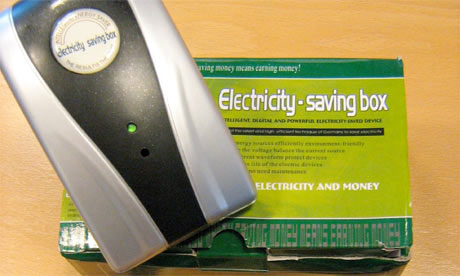
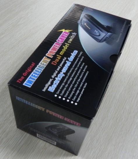
Alternative name for Power Saver: Energy Saver Power Saving Electric Saver Current Stabilizers Home Energy Saving Device Power Factor Saver Saving Saint
|
Forum comment: http://www.xtremeplace.com/yabbse/index.php?topic=78110.0
|
|||||||||||||||||||||||||
| Brands Available |
||||||||||||||||||||||||||
|
http://powersavermalaysia.blogspot.com/
|
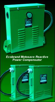
Model: MS88, MS188, MS388 A German technology. Tested by PSB (Singapore) & SIRIM (Malaysia)
|
|||||||||||||||||||||||||
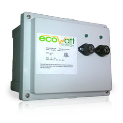
 This one is CE certified, UL listed & tested,
cULus. This one is CE certified, UL listed & tested,
cULus. |
||||||||||||||||||||||||||
 |
||||||||||||||||||||||||||
 |
||||||||||||||||||||||||||
|
|
||||||||||||||||||||||||||
 |
||||||||||||||||||||||||||
 |
||||||||||||||||||||||||||
  |
||||||||||||||||||||||||||
 |
||||||||||||||||||||||||||
|
Ultima Imaging Systems Pvt Ltd. |
 |
|||||||||||||||||||||||||
| Yueqing Chiny
Import & Export Trade Co., Ltd http://chinyichina.en.made-in-china.com/product-group/aMeJvjhEhTVo/power-saver-energy-saver-catalog-1.html |
||||||||||||||||||||||||||
|
UBRIDGE Technology http://ubridge.en.alibaba.com/product/358253955-206600002/Electric_Power_Saver_up_40_.html
|
|
|||||||||||||||||||||||||
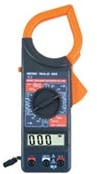 A
picture if the clamp-ammeter for measuring the current flowing through
your electrical appliances. Clamp the live or neutral wire of your
electrical cable to measure the current flowing.
A
picture if the clamp-ammeter for measuring the current flowing through
your electrical appliances. Clamp the live or neutral wire of your
electrical cable to measure the current flowing. 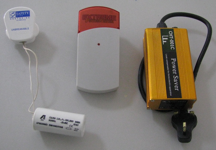


Keyword: Power Saver, Scam, home energy saving device, power saving
products, cheating, fraud, swindle, trickery, mislead