Introduction
ATMEL microcontroller is quite a popular microcontroller among the younger generation of hardware programmers due to the popularity of the Arduino IDE platform. Arduino is a higher level programming platform base on ATMEL microcontroller series. While Arduino is a very simple to use firmware programming platform for a beginner, it can be quite challenging for advanced programmer who wants absolute precision control over their software algorithm.
The popularity of Arduino results in a community of programmers sharing Arduino related information. Programmers can easily find support and resources relating to Arduino. However, the issue is that lesser programmers are now using ATMEL studio to program their ATMEL microcontroller. The resources for ATMEL studio is accurately very limited at this point in time. This is unlike the competing Microchip series microcontroller where its documentation is a lot much better than ATMEL. Now that Microchip has acquired ATMEL microcontroller business, we can expect the documentation to improve over time.
The purpose of this web page is to assist those who are new to the ATMEL Studio platform, to guide them to upload their source code (or microcontroller machine hex code) into their ATMEL microcontroller.
Things That You Need To Prepare
- Your ATMEL microcontroller
- ATMEL Studio
- Programmer tool for ATMEL microcontroller
- An adaptor board or breadboard for your microcontroller
- Wires for connection
- Firmware (a hex code file *.hex)
ATMEL Microcontroller
In this example, we are using a very simple microcontroller chip ATtiny44A from ATMEL.
The following are the pinout for the microcontroller ATtiny44A (SOIC IC package)
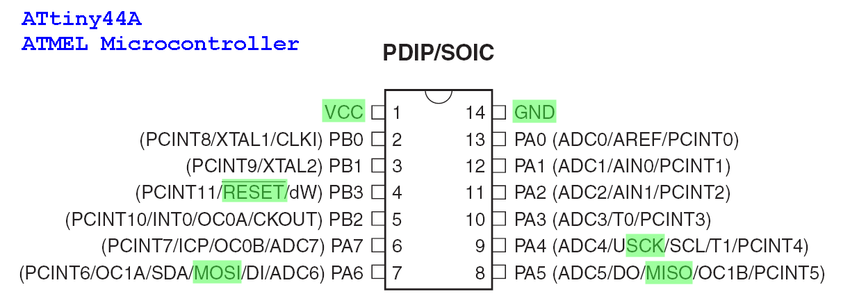
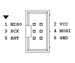
Please take note of the pins that are highlighted in green. These are the ISP programming pins on your microcontrollers. They will be connected to a programmer tool so that your firmware can be uploaded into the microcontroller chip.
The same 6 pins for ISP programming will be located at a different pin location for other ATMEL microcontroller chip part number. The firmware upload process is similar for other ATMEL microcontrollers part number. We just need to take note of the ISP pins of the particular ATMEL microcontroller.
The following are the ISP pins on a ATtiny44A microcontroller.
ISP Programming Pins for ATtiny44A Microcontroller
- MISO – Pin 08
- Vcc – Pin 01 (for powering up your microcontroller)
- SCK – Pin 09
- MOSI – Pin 07
- RESET – Pin 04
- Gnd – Pin 14 (for powering up your microcontroller)
The connection of these ISP pins to the programmer tools will be presented in the next few sections.
ATMEL Studio
ATMEL Studio is a free IDE (integrated development environment) software for development work on ATMEL microcontroller. You can write your firmware using C Programming or Assembly Language here, compile your source code into a *.hex code and download the *.hex code into your microcontroller through this integrated software platform.
Download the ATMEL Studio here.
Programmer Tool
A programmer tools helps you to connect your computer to your microcontroller chip. It is used for uploading the *.hex code into your microcontroller.
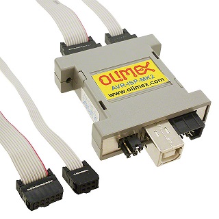
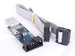
There are a number of programmer tools which allows your to upload your firmware. In this example, we are using the AVR-ISP-MK2 programming tool from OLIMEX.
Other commonly known programming tools available are ATMEL ICE and USBasp AVR.
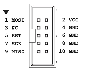
Please take note of the programmer tool pin out on their IDC connector header pins. This will be needed in the subsequent section for connection between the programmer and the microcontroller chip.
AVR-ISP-MK2 Programming Tool
Can be used for both ATMEL Studio or Arduino IDE, but need to change firmware which is very troublesome and problematic.
AVR-ISP-MK2 programmer pin out.
Arduino ISP Programming Tool
For illustration only. Not for use with ATMEL Studio.
Used for Arduino IDE
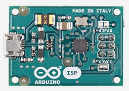
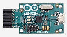
Arduino ISP programmer pin out. (Arduino ICSP pinout)
ATMEL ICE Programming Tool

ATMEL ICE programmer pin out.
USBasp AVR Programmer
USBasp AVR programmer pin out.
Adaptor for Microcontroller IC Chip
Most microcontroller chip nowadays are commonly in a surface mount package. The SMD package for ATtiny44A microcontroller is SOIC14. In order to program this SOIC14 chip, an adaptor may be needed. The following are some adaptor that you can purchase for your firmware programming.
If your circuit design has already incorporate the ISP programming pins into your PCB layout design, then you do not need to use programming adaptor socket. You just need to solder the microcontroller directly into your PCB board and download your firmware via the onboard dedicated ISP pins using an ISP programmer.
Purchase this programming adaptor test socket (SOIC14) for ATtiny44A microcontroller from dhgate.com.
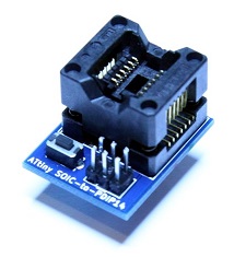
Purchase this programming adaptor test socket (SOIC14) for ATtiny microcontroller from tindie.
Wires Connection
In order for the firmware (*.hex code) to be uploaded to your microcontroller you will need to connect the ISP programmer pins to the respective pins on your microcontroller.
The following is a simple schematic to connect the ISP programming pins (IDC 10 pins header) to the ATtiny44A microcontroller.
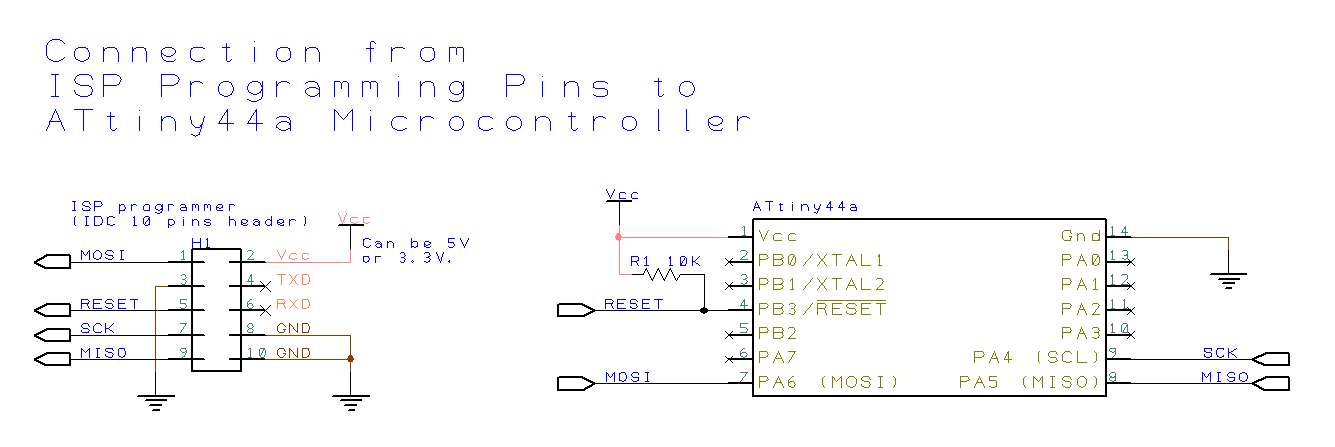
Please note that you will need a pull-up resistor of about 10KΩ between the VCC and the RESET pins.
The following section will be using the ATMEL Studio software to help us check if our hardware connection is done correctly.
Firmware
In this instruction guide, we assume that you already have a *.hex firmware available for uploading into the ATtiny44A microcontroller.
A *.hex file is generated after your project is compiled and built from your C Programming or Assembly language source code.
Device Programming
1) Atmel Studio IDE Software
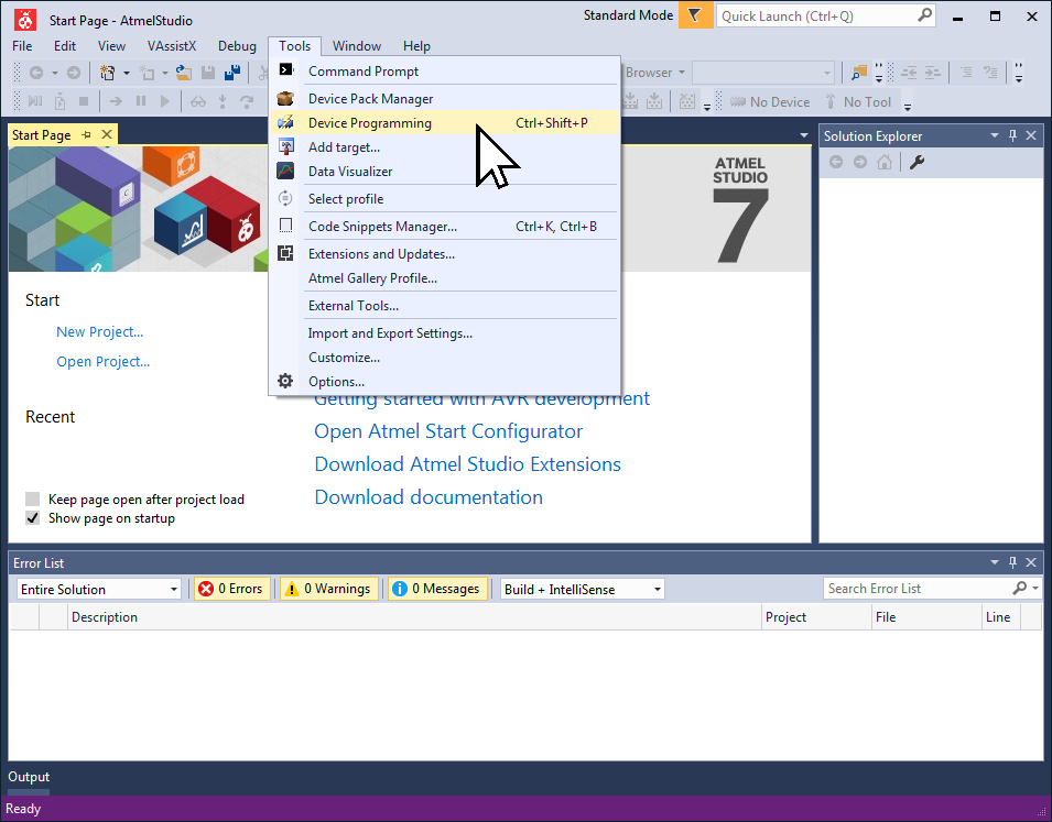
Open up the Atmel Studio IDE (Integrated Development Environment) software.
To upload a firmware to the microcontroller, open the Device Programming tools.
Under the AtmelStudio’s menu, select the menu “Tools”->”Device Programming”.
2) Device Programming Dialog
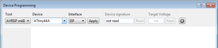
A dialog box will pops up like the one on the left.
Under the “Tool” section, select the programming tools that you got for your ATMEL microcontroller.
In this example, we are using the AVR-ISP-MK2 programmer tool from OLIMEX, so we have selected AVRISP mkII.
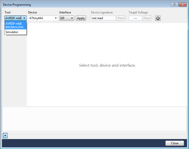
3) Selecting Your Programmer
Please ensure that your USB programmer tool is plugged to your computer. If you did not connect it to your computer, it will not appear in this “Tool” section. If you plugged in the tool, the name of the tool should reflect immediately (real-time) on this drop down menu. The name will be removed immediately when you unplug out your tool.
If your programmer tool is not listed in this dialog box, it could be the device is not installed correctly, or a wrong driver is installed. In this case, you may have to go back to your ATMEL programmer tool supplier for further assistance.
Always refer back to your programmer tool’s provider for the setting up of the tool. Different programmer tool may have a different configuration that is needed to be set up before it can upload firmware into your microcontroller chip successfully.
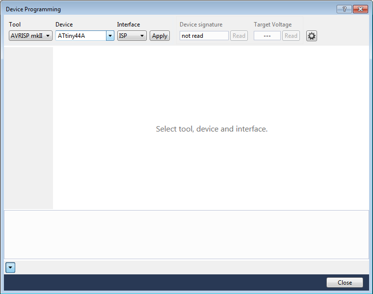
4) Select Your Microcontroller
Next. Under the “Device” drop down box, select the device “ATtiny44A” which is the microcontroller which you will be uploading the firmware to.
Keep the options “ISP” under the “Interface” menu.
Once this is done, click on the button “Apply”.
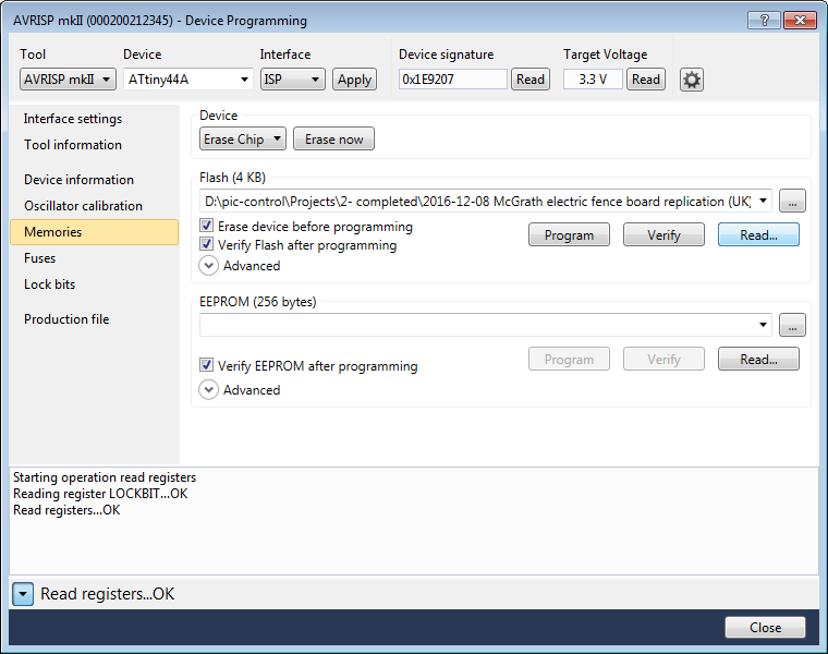
If your connection between your ISP programmer and your microcontroller is done correct, you will see a 6 digit hex code under the menu “Device signature”. In our example, we are using the ATtiny44A microcontroller. If the connection between your programmer and the ATtiny44A microcontroller is correct, you will see the text “0x1E9207” for the device signature. This is a unique ID for an ATtiny44A microcontroller.
If an error message appeared after clicking on the button “Apply”, it means that there is probably a problem with the connection. Check to confirm if the connection is wired correctly. Check if the wire is broken or if there is any wire shorted to another line. You will also need to ensure that there is a Vcc voltage of 5.0V or 3.3V on your microcontroller pin 1 and pin 14. If the microcontroller is not supplied with power, the same error message may appear as well.
5) Upload Your Firmware to the Microcontroller
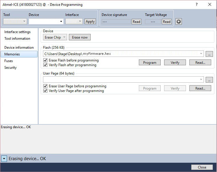
On the left-hand side of the list, select the option “Memories”. The right side of the Device Programming window will be similar to this screenshot.
Under the Flash section, click on the button “…” to select the firmware file (*.hex) from your computer system that you want to upload to your microcontroller. In this example, we are loading a filename “myFirmware.hex”.
You should check the box for the options as in this screenshot example. These settings are typical, though not very important if you forgot to select.
Click on the button “Program”. You should start to see a series of messages near the bottom of the dialog box’s screen.
The following is probably what you will see,
Erasing device… OK
Programming Flash… OK
Verifying Flash… OK
These messages indicate that your firmware is successfully uploaded into your microcontroller. You can disconnect the programmer or power off to remove the chip for further testing or use it for your production.
If an error message is encountered, repeat the checking procedure again as mentioned earlier to ensure that the programmer tool is connected correctly to your microcontroller.
Lock and Protect the firmware for ATMEL Microcontroller
There will be times you will want to prevent others from copying your source code out from your microcontroller. Most of the microcontroller have code protection bits which you can enable. Once the code protection bits are enabled, the code will not be able to be read from the microcontroller.
You will still be able to overwrite the microcontroller with new codes. After loading in the new codes, you will need to re-enable the protection bits again to lock your codes.
1) Reading from a Normal Microcontroller
Open up the “Device Programming” dialog box from the ATMEL Studio IDE. Assuming you have just upload your firmware onto the microcontroller. We are now going to read the machine code from the microcontroller.
Connect up your programmers to your microcontroller as usual. Go to the section on “Memories”, the same section where you upload your firmware to the microcontroller.
To read from the microcontroller, click on the button “Read”.
A dialog box will appear asking you for a new file name for this read file. For this example we name the file as “Document.hex”, then click Ok.
The programmer will proceed to read the microcontroller and save the machine codes onto the file “Document.hex”
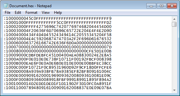
2) Code Read Result from a Normal Microcontroller
In this section, we will open the read file to have an idea how the machine codes for the microcontroller look like.
Open the saved file “Document.hex” using the Notepad.exe or other text viewer application on your computer system.
You should be able to see a long list of hex numbers similar to this example shown on the left.
You don’t have to know anything about the code. Just remember that they looks like a random chunck of numbers/letters inside the file.
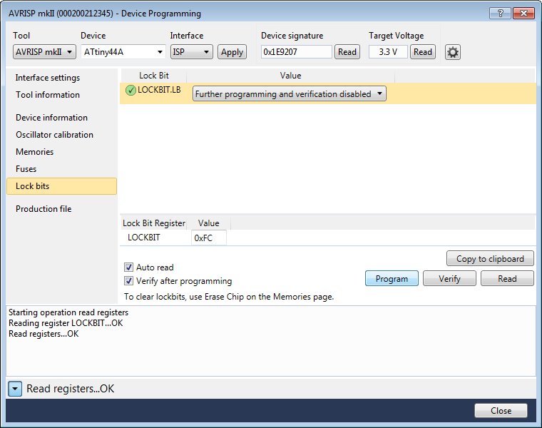
3) Set Code Protection to the Microcontroller
Next step, we are going to set a protection on the microcontroller to prevent others from reading the machine code. Proceed to the section on “Lock bits” as illustrated on the left.
Above the button “Copy to clipboard”, there is a field name “LOCKBIT”. On the right side is a text box where you can key in a value.
The default value may be 0xFF. Change that to 0xFC. 0xFC is the settings of LOCKBIT for the locking of the program’s memory inside the ATMEL44A microcontroller. The details can be found on section 19.1, pg 159 of the ATmega44a datasheet. Please note that 0xFC only works for ATMEL44A microcontroller. For other ATMEL microcontroller, this LOCKBIT code may be different. You will have to read the datasheet for the correct settings.
After changing the value to 0xFC, click on the button “Program” so that the programmer can apply this code lock setting onto the microcontroller.
There will be a series of messages which indicates that the setting is done successfully.
Starting operation write registers
Writing register LOCKBIT…OK
Write registers…OK
Starting operation verify registers
Verify register LOCKBIT…OK
Verify registers … OK
Your microcontroller is now code protected. Next, we will have to verify if we are still able to read the machine code from the protected microcontroller.
4) Read Firmware from a Code Protected Microcontroller
This is the same process that we did previously to read out the machine code.
Go to the section “Memories” and click on the button “Read” and save the read machine code in a file.
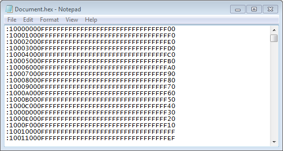
5) Code Read Result from a Normal Microcontroller
Now that the machine code is read, open up the file to have a look at the read machine code again.
It should look different from the previous read attempt. As illustrated in the left side, you should notice a lot of “F” instead of the random chunk of numbers/letters.
This indicates that the programmer fails to read out the machine code from the microcontroller. You cannot read it because the microcontroller was locked by you.
There is no way to unlock it. You can erase the memory from the microcontroller or overwrite the microcontroller with a new firmware (machine codes).
Please note that when you overwrite the microcontroller with a new firmware, the microcontroller may not be in the lock mode. To ensure your code is protected, you can proceed to the “Lock bits” to do the code protection again.
That ends the instruction for protecting your firmware on an ATMEL microcontroller chip.
C Programming, Compile and Upload Firmware
For C programming. You can open up your project files, and start editing your program, making the necessary changes. After this is done, you can press the button “F5” on your keyboard. The ATMEL Studio will compile the project, generate the *.hex file and upload the updated firmware to your microcontroller in a single step.
If you encountered errors during the compilation process, you will need to correct it and recompile again. There will be no firmware uploaded if your C programming source code contains error.