This load cell circuit module connects to a load cell sensor and provides a digital sensed value for a microcontroller to process. This circuit is also suitable for many other sensors which are of Wheatstone bridge designed. It is an ADC (analogue to digital converter) for Wheatstone bridge sensors.
A load cell is typically a Wheatstone bridge circuit. Any small change in the resistance (mili-Ohms range) can be measured. This circuit module is able to measure the small change in the resistivity of the load cell with a precision up to digital 24bits. It is able to accept 2 differential input, and selectable gain, converting the analogue sensor signal to digital.
Suitable Sensors and Application
This circuit module is suitable for interfacing to Wheatstone bridge type of sensors. It is widely used for precision measurement of tiny voltage changes from the sensor’s output.
- Load Cell
- Strain Gauge
- Pressure Sensor
- Light Sensor
- Digital Weighting Scale
|
|
|
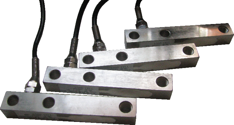
Typical load cell 1Kg, 2Kg, 5Kg, 10Kg, 50Kg, 100Kg or 200Kg (±20mV, ±40mV, ±80mV) can all be interfaced to this load cell circuit converting the precision weight pressure sensing into a digital data reading for measurement.
Load Cell Circuit Module Features
The circuit features and specification.
- 2x differential input channel, A and B
- Selectable gain x32, x64, x128
- ADC sampling speed 10Hz, 80Hz
- Accept input voltage 3.3V to 5V
- Power consumption < 1.5mA
- Operating temperature -40℃ to 85℃
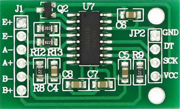
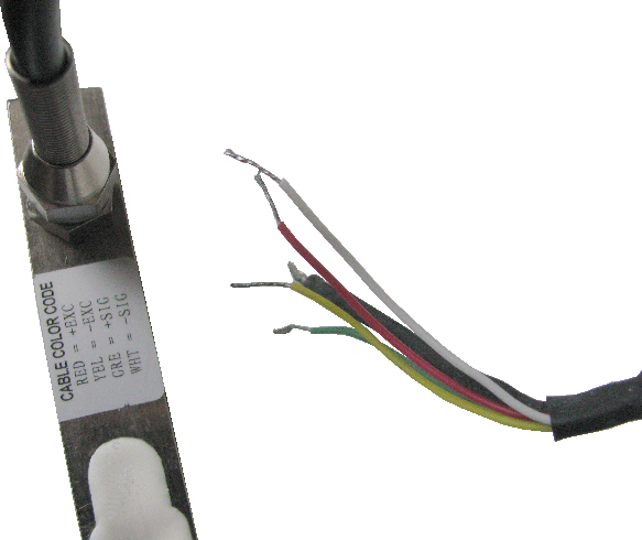
Connection from Sensor to Circuit Module
The load cell circuit consists of 6 inputs (E+, E-, A-, A+, B-, B+). It is ok to connect the terminal in the reverse polarity. The Wheatstone bridge (resistive based) sensor will not be damaged. The reading value will be reversed if the terminal is connected with reverse polarity.
Terminal E+ E-
This is the power supply to the load cell sensor or any Wheatstone bridge sensor circuit.
Terminal A+ A-
This is the input terminal of the load cell sensor or any Wheatstone bridge sensor circuit. The gain of terminal A+ A- is selectable between x64 (±40mV) or x128 (±20mV). Default gain is 128.
Terminal B+ B-
This is the input terminal for the 2nd set of load cell sensor or any Wheatstone bridge sensor circuit. The gain of terminal B+ B- is fixed at x32.
Digital Signal Output
The digital output consists of Vcc, SCK, DT, Gnd.
Vcc, Gnd
This is the voltage supply input for the board. The board can take in 3.3V or 5V without any problem. Current consumption is about 1.5mA.
SCK (Clock in)
This is the clocking input that the load cell circuit needs in order to transfer out the digital sensor reading from DT terminal port.
DT (Data ouT)
This is the digital output data which contains the load cell sensor’s reading. Data can be clocked out from this port using SCK port.
|
|
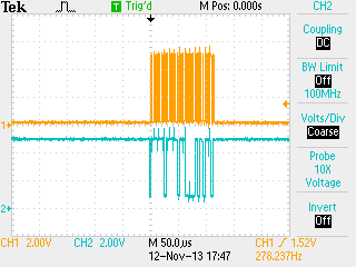
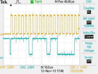
The yellow (CH1) digital signal above is the clock (SCK) send from a microcontroller to the load cell circuit board.
The blue (CH2) digital signal below is the sensor converted digital data (DT) send from the load cell circuit board to the microcontroller. You would be able to see the changing digital data from the oscilloscope when there is pressure on the load cell sensor. |
|
|
The data (CH2) is pulled low from the load cell circuit indicate that the data sampled is ready for retrieval. The clock in CH1 is clocked immediately after that.
Every positive edge of the clock (SCK) will clock out the digital bits (DT), starting from MSB (most significant bit) to LSB (least significant bit). The data can be read during the negative edge clock cycle of the SCK. Once all the 24 bits has been clocked out, a last 25th clock to the SCK input will put the DT line back to high. The last 25th clock instructs the circuit to begin sampling the channel A sensor at a gain of 128. DT high indicates that the sensor data is not ready yet. The circuit will now take reading from the sensor and converts it to a digital value. The conversion speed is 80Hz (by default) and can be set down to 10Hz by grounding Pin 15 of the IC (Pin 15, RATE). When the digital value is ready for retrieval, the DT line will be pull down to low. The whole data retrieval process will repeat again. The digital output data is a 2’s complement format range from the lowest reading 0x800000 to highest reading 0x7FFFFF. The circuit module can be powered down to save power. When SCK pin is held high for more than 60us, the circuit will be power down to a current of less than 1uA. Pulling the SCK down to low will enable back the circuit to operate as normal. The gain of input channel A can be set to x64 if the sensor dynamic range is within ±40mV. If the dynamic range is ±20mV the default gain x128 is recommended. To set the gain for channel A to x64, another clock cycle is to be inserted after the 25th clock. To sample the channel B which is fixed with a gain of x32, another 2 clock cycle is needed to be inserted after the 25th clock. |
This load cell circuit provides a precision digital data read for load cell or other types of Wheatstone bridge sensor design. For custom circuit design or digital weighing scale system for a computer, you can contact PIC-CONTROL directly for further enquiry.