Rain Sensor Awning Controller

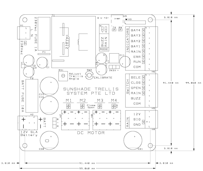
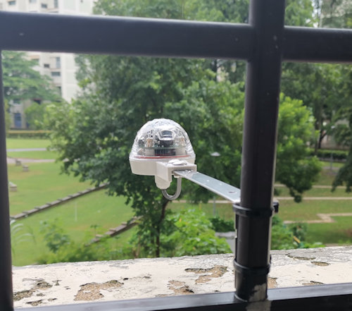
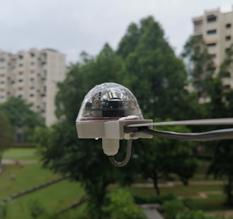
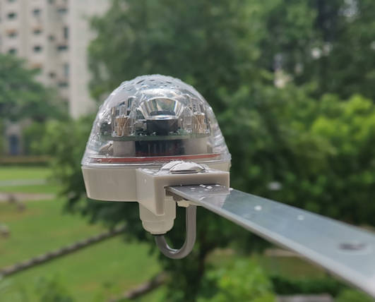
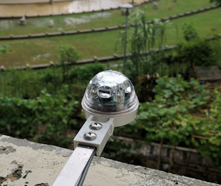
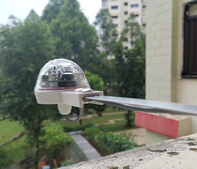
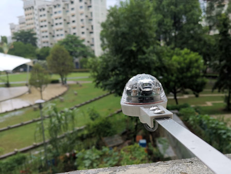
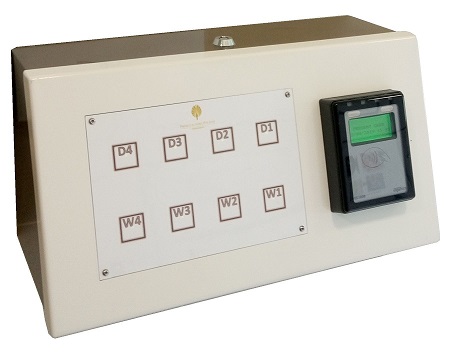
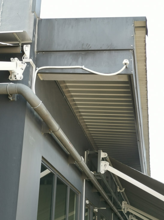
This is a timer clock awning controller for rain sensor application.

This awning will automated lower down the awning when rain is detected. A timer is available for you to set the operation timing through the week.

User Operation Introduction
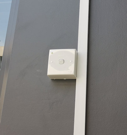
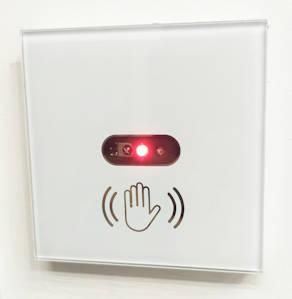
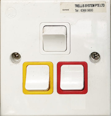
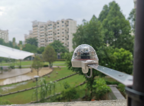
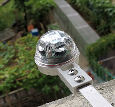
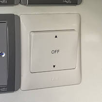
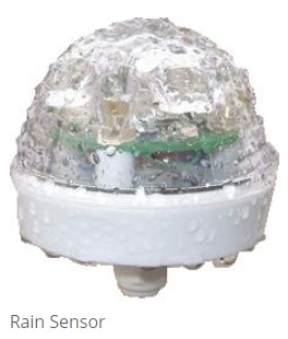
Rain sensor switch with a green LED indicator.
Awning manual control switch

Rain Sensor Switch

This switch on the wall enables user to switch the rain sensing function On/Off.

There is a green LED indicator on this switch. If there is no light on this indicator, it means that the sensing function is not in operation.

A green light on the indicator means that the rain sensing function is enable. A blinking green light indicates rain sensing enable and rain is detected.

If the rain sensing function is enable, the controller will open up the awning when rain is detected.

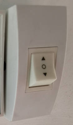
If the sensing function is disable or when there is no rain detected, the controller allows user to control the awning manually via the awning switches on the wall.

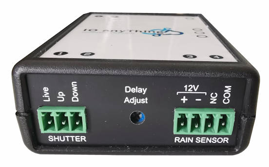
Rain Controller Description

There is a timer on the controller which allows you to set the non-operating hours of the system. Awning can be programmed to retract itself when it is off operating hour. This ensure that the possibility of damage to the awning can be minimise during windy days. When not in operation the controller will roll up the awning to keep the awning properly intact. You may also add your own wind speed sensor to signal the awning to roll up when heavy wind is detected.

Features

  1. Auto draw down awning when raining and pull up after rain is stopped.
  2. Allow manual awning control.
  3. Control awning/rain-sensor operation time period throughout the days of a week. Flexible timer controlled.
  4. Solid state power control of two awning.
  5. Allow installation of up to 2 sensor rain. For redundancy.
Rain sensor & Awning installation

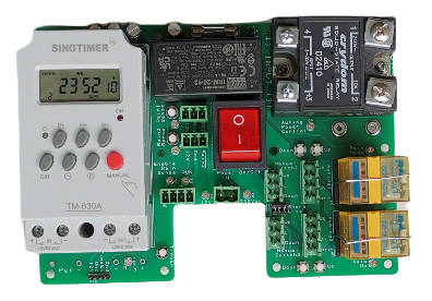
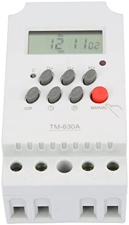
TM-630A timer module settings

The timer module is using a standard product from SINOTIMER model TM-630A. It is used to shutdown the rain sensing system operation during the day/time of the whole week.

The operating manual can be downloaded here. (0.5Mb)
Click here to download.

The module is by default in a lock state. The keypad will not be responsive until the button panel is unlocked.

SINOTIMER model TM-630A

Unlock or Lock TM-630A timer module

  1. Press the button C/R 4 times, the lock symbol on the screen will disappeared.
  2. If left unlock for a period of time, the panel will return to the locked state.
  3. You can press the button C/R 4 times to lock the panel at any time.

Manually control the relay output of this timer module

  1. After unlocking the panel, press on the Red button (labelled Manual) to toggle the relay output, On and Off.

Setting the relay output to turn on for a specific date/time of the week

  1. After unlocking the panel, press on the button P to cycle through the programming settings.
  2. The display will cycle through 1on, 1off, 2on, 2off, 3on, 3off, …. up to 28on, 28off. This allows us to set 28 different period of timing to on/off the relay output.
  3. 1on means the first set of timing to switch On the relay. (output shorted circuit)
  4. 1off means the first set of timing to switch Off the relay. (output opened circuit)
  5. 2on 2off are the 2nd set of timing to switch the relay output on/off. You can set up to 28 sets of day/timing for the whole week.
  6. Eg. For 1on setup, press the respective button H+, M+, and D+ to set the hour/min/day/days of the week to activate the relay output.
  7. The same goes to 1off to set the time/day to deactivate the relay out.
  8. Press on the button P to cycle to the next set. This will also save your settings.
  9. You can press on the button Clock to exit the programming, and press the button C/R 4 times to lock the panel.

Setting the TM-630A module’s clock

  1. After unlocking the panel, press the button CLOCK together with the button H+ to set the clock’s hour.
  2. Press the button CLOCK together with the button M+ to set the clock’s minutes.
  3. Press the button CLOCK together with the button D+ to set the day of the week.

Controller Operation

  1. User is able to enable rain sensing mode, which will pass the rights to the sensor to controlling the awning. Disabling the rain sensing mode, allows user to manually control the awning.
  2. When user leave the system on manual mode, rolling the awning up/down can be controlled via the awning wall switches.
  3. User can manually control awning when rain sensing mode is enabled and there is no raining detected.
    When raining is detected, the system will not allow user to control the awning. The awning will automatically lower down the awning. The awning will not be rolled up. If the user want the awning to automatically roll up when the rain stopped, user can permanently leave the wall switch in the up position. When the rain stopped is detected, the control will be returned to the wall switches. Though if the wall switch is at the roll up position, the awning will proceed to roll up when the rain stops.
  4. After office hour features. This feature will force the awning to roll up after its operating hour. This is to minimise the duration of the awning opened, which minimise the chance of awning being damage by strong wind.
    When the rain sensor is enabled, the awning will be force to roll up. If it is still raining after the office hour, the system will allow the awning to be in the lowered position till the rain stops. Once the rain stopped, the awning will be rolled up automatically.
  5. When the timer output is enabled, the rain sensing system will tends to auto roll up to keep the awning during time/day/days set by the timer. If this after-office-hour feature is not needed, the timer module can be removed or unplugged from the system.
  6. The solid state relay will always be switched off while the relay is switching, and will switch back after the relay switching is done. This is to protect the relay of arching.
  7. Top relay Off = Manual operation.
    Top relay On = Auto Rain Sensor operated.
    Bottom relay Off = Force awning to lower. (While top relay is activated)
    Bottom relay On = Force awning to roll up. (While top relay is activated)

Indicator Status

RUN LED Indicator

  • LED Off – No power or Rain sensing mode is not enabled
  • LED On – Rain sensor enabled (but no rain)
  • LED Blinking – Rain sensor enabled (and rain is detected)

Rain Mode Indicator

  • Off – Manual Operation (Wall switch control by user)
  • On – Auto Operation (Sensor board controlling)

Auto Up Indicator (when Rain Mode = Auto Operation)

  • Off – Force awning to open up (roll down awning to shelter from rain)
  • On – Force awning to close up (roll up awning to prevent damage from wind)

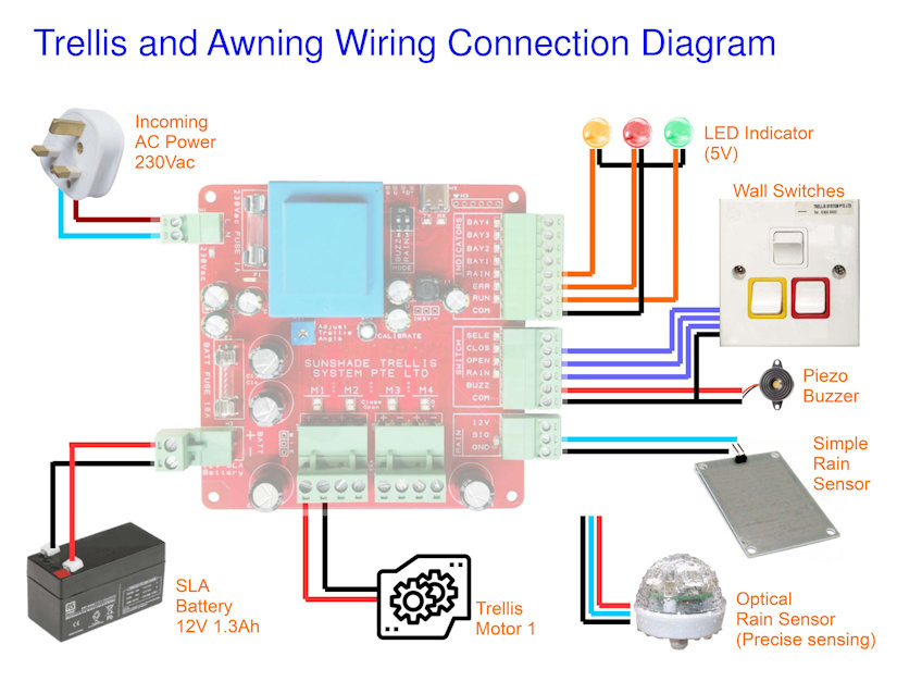
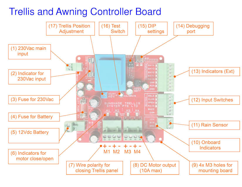
Rain Sensing Controller Schematic

Rain awning schematic

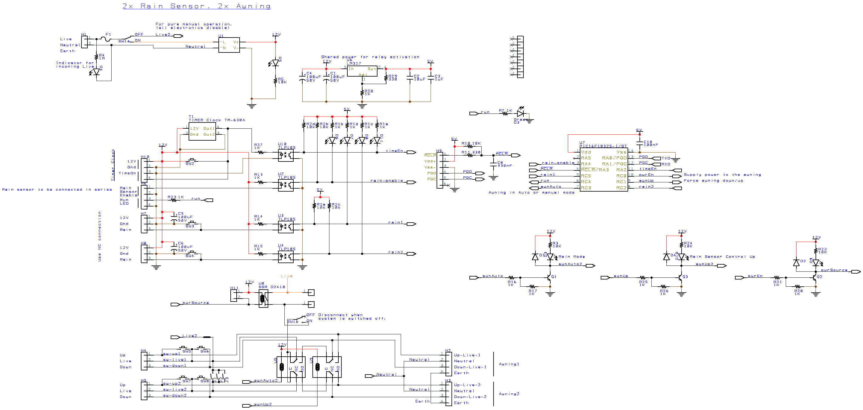
Main Switch Function

The Neutral line is common to all. Live1 is the AC power line when the main switch is in On position (switch is downwards). This will activate the microcontroller and rain sensing electronic to function.

When the main switch is in the Off position (switch upwards), the entire electronic is not power up, and is not in operation. You will only see the green LED for 230Vac faintly lighted up. The rest of the LED are off. In this position the awning get access to direct power connection. This is as if the awning system works manually as normal. The Rain sensor controller is being by-pass. This allows for direct troubleshooting works on the awning without involving the rain sensing controller.

Relay U5

The function of this relay is to divert the incoming 230Vac (through the solid state relay U8) to either the manual control wall switches or to Relay U9 which forces the awning to open up, or roll up. Default relay position is allow manual control from the wall switch.

Relay U9

The function of this relay is to force the awning to open or roll up when Relay U5 is activated. Default relay position is to force awning to open its shelter for sheltering from the rain.

Solid State Relay U8

The function of this relay is to switch off the 230Vac power source while the relay U5 and U9 takes their time to switch. Doing this can prevent the mechanical relay U5 and U9 from contact welding problem. Meaning the relay switch becomes sticky because of the high voltage spark created during the switching. It improve the life span of the mechanical relay.

Reference

Contact us for further details.

Switching Relay Output using Audio Signal

Audio Controlled Relay ST-ACR1

Application

  • Switching Controlled by Audio Signal
  • Switching from Mic or Line Signals
  • Silence Sensing
  • DPST switching relay output
  • Open-collector slave output

Connection Setup

Audio input, Light output
Alarm signal trigger system

Device Wiring Connection

Audio wiring input connection

The module uses 24Vdc for powering up the audio sensing input and relay output.

Power supply connection

Manual input to control the output relay.

Adding manual control

You can purchase the module ST-LCR1 to extend out for more relay outputs.

Adding more relay output for interfacing to external system.

Specification

  • Audio input: 10Kohm balanced bridging
  • Input connections: may be connected balanced or unbalanced
  • Control output: open-collectpr @ 25mA
  • Retrigger delay: 250ms
  • Relay output DPDT (up to 230Vac, 2A)
  • Activation response time: 25ms
  • Dimension: 17 x 76 x 39mm

Dimension

Product dimension size

Size Dimension

Audio Controlled Relays (other models)

ST-ACR1 Audio Controlled Relay

Relay is actuated by audio line level source.

ST-ACR1M Audio Controlled Relay

Relay is actuated by microphone input source.

ST-ACR2 Audio Controlled Relay

Can be used as a silence sensor detection device. Relay release delay is extended by 5-50sec.

ST-LCR1 Logic Controlled Relay

Logic controlled relay. Relay output is DPDT (dual pole dual throw)

ST-LCR2 Logic Controlled Relay

Pulsed controlled relay. Relay output is DPDT (dual pole dual throw)

ST-VOX1 Voice Activated Relay

Voice controlled relay output. Input voice can be from microphone or audio line level. Can be used in a voice intercom setup.

Advertisement…

Audio Activated Relay PIC-125

Click here to but Audio Activated Relay [PIC-125] product.

MDB Converter Products

Looking for MDB converter products for your vending or dispensing machine?

Here is a list of MDB converter available on the market.

MDB to Pulse Converter

This image has an empty alt attribute; its file name is mdb-pulse-converter-pic-031-layout.jpg

A simple Plug-&-Play solution to converter your pulse-based vending machine into a machine that can collect cashless payment (Credit Card, RFID, QR code, etc…)

You can now collect many types of cashless payments from any modern payment terminal that uses MDB (Multi Drop Bus) connection, a very common communication standard that the vending industry has adopted. A modern payment terminal can now accept cards like Visa, MasterCard, NFC, QR Code, PayNow, etc… . many more…

You do not need to understand the technical part of MDB. Simple to setup. Connect the select buttons and this board can trigger the payment terminal to collect the payment amount that you have setup.

Company: PIC-CONTROL Pte. Ltd.

Website: https://www.pic-control.com/pic-031-mdb-pulse-converter/

MDB to VCCS Converter

VCCS protocol is commonly used in Japan’s vending machine. Japan vending machines are highly sought after. Communication poses an issue because VCCS is not easy to deal with. There is hardly any documentation relating to the VCCS protocol.

This converter allows a cashless payment terminal (using MDB protocol) to connect and talk with a Japan vending machine system (using VCCS protocol).

This converter allows the more popular MDB protocol (commonly used by vending machines all over the world) to connect to a VCCS vending machine.

This MDB to VCCS converter product is available here. It is distributed solely by MobileEFTpos in Singapore.

Company: Mobile Eftpos (asia) Pte Ltd

Website: https://www.eftpos.com.sg/

MDB to VCCS converter

MDB to RS232, RS232 to MDB Converter

This is a simple MDB to RS232 or RS232 to MDB device. Very useful in troubleshooting MDB issues through monitoring of the MDB communication line between your devices.

A handy tools

Company: Wafer

Website: http://www.waferstar.com/en/MDB2PC-PC2MDB.html

MDB Converter & Raspberry Pi Hat.

MDB Converter 4

Interface MDB via proprietary serial communication. Allows you the flexibility to interface with MDB without needing to deal with the complicated MDB communication protocol.

Company: Abrantix

Website: https://blog.abrantix.com/webshop/

VE9390 – PULSE to MDB Conversion Kit

Proprietary MDB converter. Contact the company for further details.

Company: Vendors Exchange International

Website: https://www.vesolutions.co/MICRO-MECH-MDB-CONVERTER-WITH-DEX-V350

https://www.veii.com/PULSE-AMUSEMENT-TO-MDB-KIT

PICOVEND MDB Converter

This interface offers a convenient solution for modernizing parallel/pulse operated vending machines with up-to-date MDB payment systems, which also encompass bank card readers. It can be utilized for a variety of machines such as those dispensing hot drinks, universal items, self-service setups, kiddie rides, and more.

Company: PICOVEND EZ

Website: https://picovend.com/index.php

MDB-USB Interface

MDB to USB Interface by Qibixx

A very comprehensive MDB device that has many powerful features to convert, diagnose, troubleshoot, and develop MDB-related projects.

Effortlessly connect VMCs to Multi Drop Bus devices on Linux, Mac, and Windows. Uncover cashless possibilities and data insights with Master & Slave functions. Customize the MDB interface, or utilize Stand-alone mode for payments and relays.

Company: Qibixx

Website: https://mdb.technology/

PC to MDB

Introducing the PC2MDB™: Revolutionizing Vending with PC Integration

The PC2MDB™ transforms the landscape of vending machines by seamlessly integrating a PC into the equation, bridging the gap between controllers and cashless transactions. Utilizing the PC’s RS-232 port, this innovation empowers the PC to operate as a cashless slave device, extending its capabilities to the vending realm.

With PC2MDB™, existing vending machine controllers (VMC) are effortlessly managed via a PC. The interface enables the PC to function as a cashless device, redefining payment methods. Compatible with both PCs and Programmable Logic Controllers (PLCs), it establishes a universal line of communication with all vending machines utilizing the MDB protocol, regardless of their manufacturer.

Enhancing its adaptability, PC2MDB™ offers multiple interface options, including Serial, Ethernet, and USB connections. This diversity makes it a potent and versatile solution for deploying distinct payment systems that require the integration of a PC or PLC alongside vending machines.

Experience a new era in vending technology with PC2MDB™, where seamless integration meets expanded possibilities. Elevate your vending operations today.

Company: Upstate Networks Incorporated

Website: https://www.upstatenetworks.com/

Customised MDB converter projects.

Do you need help in developing a customised MDB converter or interface board to solve your vending integration problem?

You can contact us. Tell us more about your entire vending system, and the help and support you need for the engineering integration work.

Touchless Lighting Wall Switch

Touch-less lighting wall switch. Switch On/Off your room lighting without touching the wall switch.

Suitable for installation at public area or high traffic user premises.

Reduce germs bacteria virus condemnation.
Minimise touch surface that can have direct contact with Covid virus.

Touchless Lighting Wall Switch
Video Demonstration

Build-in electronic IR sensor is sensitive to hand activation on the wall switch. Wave one time to turn on the lights and wave again to turn it off.

Simple and sensitive touchless hand wave wall switch sensor. Very simple to use.

Contact us at sales@pic-control.com for further information.

Check out our series of touchless contactless electronic wall switches for your other application.

Trellis Automated Roof Panel System

Product by Sunshade Trellis System Pte. Ltd. (Singapore)
Visit website: https://sunshadetrellis.wixsite.com/home

Introduction

Automatic motorised Trellis system to shelter you from wet rain and hot sun shine, while you still get the fresh airy breeze. Louvered roof panel system installed with a rain sensor to automatically close the panel when it rains.

Installed Examples of Trellis Roof Shade System

Airy indoor open space using Trellis roof system.

The trellis roof can also be installed for indoor/outdoor balcony to create a spacious cool and relax area.

Feel the outdoor air breeze without too much hot and sunny sun shine. Nice natural lighting and cool open space.

This aluminum roofing system is designed to be light weight yet robust against strong wind and rain fall. Suitable for indoor and outdoor installation.

Trellis open close roof shade system for outdoor swimming pool.

Trellis roof system provides shades for your outdoor pool during a sunny day as well as raining days.

When the weather is good, the trellis can be open up to allow for shine and breeze through the open area.

Enjoy your pool with comfort.

Trellis shade roof system for indoor corridor.

This is an indoor trellis roof canopy structure installation for a corridor inside the house.

Allows outside natural light and air breeze to enter into the house.

Makes the house cooler, brighter while using less energy.

The rain sensing mode will automatically close up the trellis to ensure that your indoor environment is keep dry and clean.

Operating Instruction

The trellis roof control is simple to operate. One button to open and another button to close the trellis.

The trellis system also comes with a rain sensor. When rain is detected, the trellis shelter can automatic close up itself so that your corridor stays dry.

An optional external buzzer can be install for auditory feedback to the user.

Opening Closing Trellis

A single push and release on the open button, the trellis will open to its preset half opening position. This preset position can be adjusted form the blue color POT on the circuit board. Another push and release will fully open the trellis.

A single push and release to the close button will fully close the trellis.

For controlling of the trellis opening to your preference, you can simply push and hold the button, to open/close the panel, and release the button when the panel reaches the position that you want.

Rain Detection

Rain detection mode can be activated to automatic control the trellis when it rains. The trellis will automatically be closed and do not allow to be open until the water gets dry out.

To open the trellis manually while the trellis is still wet, you have to switch off the rain detection mode first.

User can select this rain detection mode via a switch. The rain sensor mode indicator will get light when this mode is selected. When it is in OFF mode, the indicator will be turned off. This indicator will blink when rain is detected. If the rain mode is switched ON, the lighted indicator will starts to blink when rain is detected. Even if the rain mode is switched OFF, the indicator light will still blink when rain is detected, just that the blinking rate is slower.

System Connection Wiring

This section shows how

Wall switch to open/close the Trellis and to set for rain sensing.
Wiring Connection Diagram (for single bay Trellis installation)

Low cost rain sensor can be connected to this board to detect raining event. If the rain sensing mode is active, the trellis will automatically close itself to shelter away from the water. If you like the trellis to reacts faster to the rain, you can choose to install optical rain sensor instead. It is more precise in the rain sensing and can react faster to raining and rain stopping. You can order optical rain sensor from PIC-CONTROL.

Trellis Roof Controller Board

This is the main controller board for the trellis automated roofing system. It is the main board for driving the geared DC motor of the trellis system. Design to drive geared DC motor with a rating at about 1A (when it moves), and a stall current at about 8A to 10A.

The following is the description of the controller board.

Electronic controller circuit board for Trellis Roof Shade System.

(01) 230Vac mains incoming power input

230Vac is required for charging of the SLA battery.

(02) Indicator for 230Vac incoming power

Green indicator will gets lighted up when there is power coming from the 230Vac input.

(03) Fuse for 230Vac

Fuse of 1A is recommended for protection from the 230Vac incoming mains power source.

(04) Fuse for Battery

Fuse of 10A to 15A is recommended for protection from the battery.

(05) SLA Battery

Sealed Lead Acid Battery. Recommending 12V 1.3Ah capacity battery (97 x 43 x 51mm). Larger size 12V 7Ah SLA battery (152 x 66 x 94mm) can also be use.

This battery is used for driving the DC motor of the Trellis.

(06) Indicators for Trellis motor

When the controller is driving the Trellis motor to close, Green indicator will gets lighted up. For opening of the Trellis, Yellow indicator will gets lighted up.

(07) Motor Wire polarity (closing the Trellis)

Motor wire polarity for closing the Trellis panel is motor positive terminal on the left (pin 1), and negative terminal on the right (pin 2). Apply this polarity should activate the motor to close the Trellis.

(08) DC Motor output

DC motor output is design for driving a DC motor up to a maximum current of 10A. Typical operating current is about 1A, and can spike up to 8A to 10A when the motor is in a stalled position.

(09) Mounting Holes M3 x 4

Mounting holes available at the 4 corner of the board. Design for M3 screw mounting. Distances between the mounting holes are about 91.5mm apart.

(10) Onboard indicators

Indicators onboard for technician monitoring and troubleshooting use.

(11) Rain Sensor interface

This interface allows a simple resistivity rain sensor to be connected via two wire, signal and ground pins.

It can also connect to a more sensitive and responsive optical rain sensor for a better user experience.

(12) User switches and buzzer interface

Switch buttons for user to control and beep sounder feedback.

  • Open Trellis
  • Close Trellis
  • Rain Sensing Mode
  • Bay Select
  • Beep Sounder

(13) External Indicators

User indicators for operation and monitoring.

  • RUN
  • ERROR
  • RAINING
  • BAY 1 (available in 4 bay controller board)
  • BAY 2 (available in 4 bay controller board)
  • BAY 3 (available in 4 bay controller board)
  • BAY 4 (available in 4 bay controller board)

(14) Debugging port

USB debugging port for monitoring purpose. It is a virtual serial communication port with the following settings,

  • baud-rate 115200bps
  • No Parity
  • 8 Data bits
  • 1 Stop bits

(15) DIP switches

— Not available —

(16) Test switch

— Not available —

(17) Trellis position adjustment POT

When the open button is pressed for the first time from the Trellis panel closed position, the panel will open to the half open panel position. This half open panel position can be adjusted to your preference by adjusting this (17) Trellis position adjustment POT.

Battery Power and Protection System

The whole system is powered by a 12Vdc SLA Battery (Sealed Lead Acid Battery). A battery capacity of 1.3Ah is enough for typical operation.

The charging of this SLA battery is supplied via the 230Vac power input. This power do not supply power to the trellis. It is only used for charging the connected SLA battery. If the SLA battery is not connected, the system will not be able to operate correctly. This 230Vac do not have enough power to drive the trellis motor. A 1.3Ah SLA battery capacity can drive the Trellis for about 30min to 60min without any charging. It is ok to install a high capacity battery if want the system to operate longer when AC power is not available (A power blackout scenario).

A battery monitoring is designed onto the system. If the voltage level of the battery falls below a healthy level, the ERROR indicator will start blinking. When this happens, the controller will only allow user to close but not open the trellis. This is to protect the battery from over draining itself, and to conserve the energy so that it can have enough power to close up the trellis when it detect rain. If the blinking appears, you can simply wait for a while. The battery will be charged up, and allow for normal operation again. This can happen when someone is operating the trellis for a continuous period of 30min or more, or if the battery becomes faulty after long use.

It is recommended to replace the battery every 4-5 years of operation.

The system ERROR indicator will appeared to blink faster if the battery is suspected to be faulty. If this happens, leave the system alone for 24 hours. If the ERROR indicator blinking persist, please contact for technical support. It could likely be cause by the following…

  • No incoming 230Vac power supply.
  • Faulty charging circuit.
  • Battery is faulty (normal wear & tear).

The technician will diagnose and help you rectify the problem.

Technical Specification

  • Board power consumption is about 1W, up to 12W max
  • AC Power Input: 230Vac 0.1A (for battery charging purpose)
  • DC Power Input: Sealed Lead Acid Battery SLA 12Vdc 1.3Ahr (for motor operation)
  • Output driver support geared DC motor of 12Vdc 1A (10A max rating)
  • Support low cost resistive, or high precision optical rain sensor.

Cable current capacity for the Battery and Motor can operate peak at about 10A. Cable gauge size of AWG16 is recommended.

Trellis Controller Board Dimension

The physical board size is about 99 x 99 x 36mm.

Propose M3 mounting hole position is 91.5 x 91.5mm.
(mounting hole size is 3.2mm, suitable for M3 size screws)

Trellis Controller Board Dimension

The weight of this board is about 350g.

Deployed Site Installation

This is a installation for a single bay Trellis controller.

The board requires a 12Vdc Seal Lead Acid battery to function and for powering up the motor. Battery as small as 12Vdc 1.2Ahr battery can be use. (can continuously operates for about 45 minutes without the charging 230Vac power mains)

Trellis controller installation

Troubleshooting

Symptom ObservationPossible Cause
Error Buzz ToneThis is the most common feedback from a user. A low sound tone sounded when the switch is pressed. This can occurred when the Trellis is not allowed to be opened when it is raining and the rain sensing function is enabled.

Error buzz tone will also sound when you are trying to open the Trellis when the battery charge is low or the battery is faulty.
ERROR Indicator Blinking (slow).Battery voltage is low. Low in charge. This may also happen if 230Vac is not connected, or the charging circuit is faulty. If the system has been operating open/close action for long period of time, this may happen too. To conserve energy during this period, the Trellis can be close but cannot be open. You can wait for 24 hrs for the battery to be charged up before you can operate it normal again.
ERROR Indicator Blinking (fast).Battery voltage is super low. Battery probably needs a replacement.
Please call for technical support.
Cannot open Trellis.Check if ERROR indicator is not blinking. If it is blinking, read up the possible cause above. You can

If the Rain indicator is blinking.
The Trellis will not allow to be open, if battery level is low. You can wait for 24 hrs for the battery to be charged up, and attempt to open again.
The trellis will also not open if the rain sensing is enabled and water is detected. You can disable the rain sensing function, and open the Trellis.

If no indicator is blinking and the Trellis cannot be open, please call for technical support.
Cannot close Trellis.Please call for technical support.
Trellis do not automatically close when it rains.Please ensure that the rain sensing mode is enable.
If rain sensing mode is enabled and the Trellis do not close automatically when it rains, please call for technical support.

Board Voltage Measurement Test

When doing this measurement to test if the board has all the voltage at the correct level, the battery has to be disconnected, and the AC main power input has to be switched on.

With reference to the Gnd pin, the voltage measured from the board labelled no. 1 to 4 should be as follows,

  1. Vcharge = 14.4V ±0.2V (battery charging voltage)
  2. Vbatt = 13.7V ±0.2V (battery voltage)
  3. Vcc = 13V ±0.2V (unregulated supply to the circuit)
  4. 5V = 5V ±0.06V (regulated supply to the circuit)
Checking voltage measurement point on the board.

Fast measurement tips:

The voltage different between point 1 and 2, point 2 and 3 is about 0.7V differences.

Contact Us for further details.

This system is designed and sold by Sunshade Trellis System Pte. Ltd.

Contact them at +65 6368 9800 (office phone), sunshadetrellis@outlook.com (email)

Click here to visit their website at https://sunshadetrellis.wixsite.com/home

Also check out other automated awning retractable roof shade system.

Shutter Control with Rain Sensor

No more worrying about the rain.

Use a rain sensor to automatic control your motorised roller shutter control to prevent rain water from splashing into your premises.


Rain Sensor

This rain sensor requires little maintenance as there are no mechanical parts or metal part that is expose to the wet environment.

The electronics is seal in a clear water-proof dome shape enclosure.

Simple sensor to detect and control your shutter.

Click here for more information about this rain sensor.


Motorised Roller Shutter Control

This is a 230Vac motorised roller shutter installed in a kitchen of the HDB flat. The shutter is open to allow natural air breeze to come in. When it rains, this shutter is automatically closed with the help of the rain sensor and a controller.

Shutter Open

Shutter open

Open shutter door to allow fresh air and breeze into the house.

Shutter Close

Shutter close

Shutter is automatically closed when rain water drops is detected by the rain sensor which is installed right outside this shutter.

Rain sensor mounted outside the window grill.

Wall Switch for Shutter

Wall switch for manual overwrite of the roller shutter up/down control

Manual Mode

The user can use the wall switch to manually control the shutter by pressing the up or down switch.

Auto Mode

Leaving the switch in the middle will leave the system in the automatic mode. This means the rain sensor will be in control.

When it rains, the sensor will close the shutter. When there is no rain for a period of time, the sensor will automatically open the shutter.


Rain Sensor Controller

Controller for Raini Sensor

A rain sensor controller interface between the rain sensor, the motorised roller shutter, the wall switch control panel and the electricity power.

For more information about this rain sensor controller, please click here.


Rain Sensor Installation Photos

Depending on how fast you want the sensor to be activated, the sensitivity of the sensor can be adjusted. In typical installation, we will set it to the most sensitive.

A custom mounting bracket can be use to extend out the sensor. This will help the sensor to activate the shutter close earlier before the rain gets splash into your home.

Rain sensor is extended out from the wall to detect the rain outside.
Robust rain sensor under the hot sun.

Relevant Post

Automatic Identify Cable Connection | Wiring Trace & Map Productivity Tool

Are you looking for a tools that can help you identify and trace out the connection from your complex chunck of cable & harnesses with a press of a button?

Get hold of this awesome engineering tool for your electronic lab.

This tester maps out the connection of your cable saving you time and provide you with accurate results.

Advantage

  • Generate a comprehesive pin to pin connection report.
  • Fast.
  • Accurate connectivity report.
  • No more human error in your diagnosing of the cable wires connection.
  • Decide complex wiring connection.

Examine the pin connection at a glance through the generated mapped connection report.

Automatically mapped out all the wiring on the cable for you. You do not have to trace each pin connection one by one. You will get instant result through the generated test report.

No matter how complex your cable or harnesses is, the process of decoding your wire connection is still the same.

Simply connect each connector pin wire to one of the terminal on the PIC-350 connection decoder, it will automatically trace, identify and mapped out all the connection for you.

The only thing you need to do it to analyse the generated report and document the results.

Simple. No more painstaking connection measurement, checking pin by pin manually using a multimeter.

PIC-350 is an awesome and smart X-ray tool for your cable wires reverse engineering work.

A productivity tool that an electronic engineer will keep on their engineering work bench.

A great tool to discovery the connection of a new or unknown cable. Can also be use for trace passive connection on your PCB circuit board.

– Cable connection reverse engineer tools
– Cable connection tracer, mapping
– Auto mapping of complex cable wiring connection.
– Auto detection of wiring connection


Check out more information about this cable connection analyser product PIC-350.


Cable Connection Assembly Tester

Cable Connection Assembly Tester

A simple to use cable-tester. One touch button to learn from your master cable, and another button to test your production cables.

Setting Up for Cable Testing

The following is a guideline to using this cable tester to test your cable or wire harness.

  1. Get ready the cable that you want to test.
  2. Prepare the mating connectors for your cable.
  3. Crimp, solder or attach a wire to each pin of the mating connector.
  4. Connect each of the wire to each of the terminal port on the Cable Tester. (You can connect up to 64 points)
  5. Power up the cable tester via the USB mini-B socket.
  6. Connect your Master cable to the mating connectors that are now attached to the Cable Tester.
  7. To learn the wiring of your Master cable, press and hold the small learning touch button on the Cable Tester device. Hold it for about 3 sec until you hear a double beep or see the PASS & FAIL LED flashing.
  8. The Cable Tester device has learned your Master cable.
  9. Remove the master cable from the mating connectors.
  10. Replace it with the production cable that you want to test.
  11. Press on the “Start TEST” to begin testing the cable. The test result will be available almost instantly within a second.
  12. You should be able to see a green LED PASS lighted up if the cable has the same wiring configuration as your Master cable.
  13. If the cable is not the same, you should see a red LED FAIL light up.

Cable Connection Test Report

This cable tester can also be connected via a USB cable to the computer for the display of the cable test result report.

You can use the following software to view the cable tester connectivity report.

Communication baudrate settings: 115200bps, 8 data bits, 1 stop bit, no parity bit, no hardware flow control.

There are a few commands which allow you to measure and generate the cable wiring report.

  • Generate a test report with reference to your master cable.
  • Current cable connection report.
  • Master cable connection report.
  • Learn cable connection and save the wiring configuration as the master template.

Through this report, you are able to see at a glance how a cable is being wired. A master cable wiring configuration can be saved to this tester. This tester can then base on this master cable wiring pattern and test the rest of your production cables.

Cable connection test report

Up to 64 connection points can be tested. A1 to A8 …. to H8 represent the 64 terminal points on this Cable Tester device.

Total EEPROM memory required for 64 connection is 4Kbits (64 x 64 connection points).

Test Result Example:

O – Correct Connection      
M – Missing Connection      
X – Wrong Connection      
– Correct No Connection      
         

Fully Automated Test Solution

This cable tester can also be integrated into your production machine for a fully automated test system for your cables.

Click here to check up more details of this PIC-350 Cable Harness Connectivity Tester.


Customised HAT | Attachment Board for Raspberry Pi

 Custom HAT, attachment board for Raspberry Pi

Customised Module for Raspberry Pi

We can help you customise an attachment suitable for your application.
Ensure that you device can be as compact in size as possible.
Neater and more reliable wiring connection.

Consolidating your circuit modules onto a single Raspberry Pi Hat module.

Raspberry Pi Stacking attachment board design


More customise features

  • Power up your Raspberry Pi from a wider input voltage range from 12Vdc to 24Vdc.
  • Communication feature RS232, RS485, Zigbee, Wifi, etc…
  • Digital I/O (input/output).
  • Analog signal sensing inputs.
  • Sensors inteface.
  • NFC or RFID attachment.
  • LED lighting effect control.
  • Motor driver and control.
  • GPS geographic location sensing.
  • User Graphic Display.

Contact PIC-CONTROL in Singapore for more information.

Other Raspberry Pi Form Factors and Models

Raspberry Pi Model BRaspberry Pi Model ARaspberry Pi Zero

  • Raspberry Pi 3 Model B+
  • Raspberry Pi 3 Model B
  • Raspberry Pi 2 Model B
  • Raspberry Pi 1 Model B+
  • Raspberry Pi 1 Model A+
  • Raspberry Pi 1 Zero W (with wireless and Bluetooth)
  • Raspberry Pi 1 Zero
  • Compute Module 3, Module 3 Lite, Module 1
  • Compute Module IO Board V3

Raspberry Pi Compute ModuleRaspberry Pi Compute Model I/O Board

References

Cashless Payment System Singapore


Looking for a cashless payment system for your automated machines?

PIC-CONTROL provides solution to allow your machines to accept cashless payment in Singapore.
We have a simple package plan to help you automate your machine to collect payment 24 hours a day, 7 days a week.

Advantages of a Cashless Payment System

More and more customers are using a cashless card to make payment for their purchase. Customer may not have enough cash notes/coin but they definitely have a cashless card for their daily shopping or transportation in Singapore.

  1. Increase Sales
  2. Fast and Convenient
  3. No more collection and handling of cash money notes/coins
  4. Reduce the administration, operation, maintenance and banking cost.
  5. Daily transaction report
  6. Able to accept a variety of payment amount (unlike a notes or coin acceptor).
  7. More robust (no mechanical part)
  8. Customer does not need to look for cash notes/coins for the purchase.
  9. Machine does not need to return change or hold cash.
  10. Contactless payment. (Hygiene from germs, bacterial compared to notes/coins)

The use of a cashless payment system eliminate the need of handling of coins. Coins handling charges by the bank can be very costly.

Application

More and more customers are carrying less cash (coins and notes) in their wallet. Cashless is more convenient and faster transaction. Improve and automate your sales by using a cashless payment system.

Cashless Payment for soft drinks dispenser mahine     Cashless Payment for snacks vending machines     Cashless Payment for Toy Catcher machine

Cashless Payment for Drink dispenser machine     Cashless Payment for Coffee Machine     Cashless payment for Kiddy Ride machine

Cashless Payment System for Machines

We offer Rental Package

For $5-$8 dollars a day (yearly package), you will get to own your cashless payment system
to increase your sales and improve your operational efficiency.

Monthly/Weekly rental is also available. Please contact us for the package rates.

Why Rental?

Focus on your business and leave your engineering headache to us.

We have design this package to help businesses cap the cost of maintaining a cashless payment system, as well as lowering the initial engineering cost. Simple to understand price ceiling so that you will not have any price shock.

Technical engineering care support is inclusive in this rental package to ensure that any of your technical problem will be resolved. Free consultation on your machine even if it is not relating to the payment system. This is our support to ensure that your machine will operates smoothly. You success is our success.

Cashless Payment System Singapore

Package Monthly Rental Rate (2 years contract, billed yearly)
[1] Wired internet connectivity available onsite. S$170 per month
[2] No internet connectivity available onsite. or Wireless connectivity. S$230 per month

** Rental package is INCLUSIVE of integration work. Subjected to our sales engineer’s assessment.

** Typical lead time for the engineering integration work takes about 6-8 weeks time.

** Standard vending payment procedures. (MDB Payment Terminal model)

** Price package is subjected to our project feasibility assessment.

Charges

We would like to make the pricing clear and simple to understand for our clients.

  • 1 year advance rental payment. (assuming Package [1], this will be S$1800)
  • 3 months rental deposit. (assuming Package [1], this will be S$450)

The total down payment for Package [1] is $2250 + GST.
Subsequent rental payment will be collected yearly in advance.

Other charges

  • Per transaction charges (typically 0.8%, 1.6% to 3%-5%). Depending on your selected payment service provider. Ezlink, Nets and Banks for (Visa, MasterCard)
  • Opening of account is required for each type of card payment that you want to accept. There is no charges to the opening of the accounts from us. Some banks or service provider may charge a small fee for using their facilities. You can source or negotiate for a better rate.

Not inclusive of

Every project is unique on its own. If your project requires additional complex work there may be additional engineering cost involve. We can waive off simple engineering work. Please contact us for an assessment. The additional cost would probably comes from the following scenario.

  • Electrical and cabling work.
  • Complex custom enclosure work.
  • Complex integration work.
  • Non-standard vending payment procedure. (Customised payment process, or non-MDB payment process.)
    Click here to read more about the standard MDB payment process here.
  • Additional note collecting peripheral (+$50/month)
  • Additional coin collecting peripheral (+$10/month)

Site infrastructure that you should provision for your project

The following are some of the infrastructure you can start to provision for your cashless payment system.

  1. 1x or 2x Power Point Socket
  2. 1x Ethernet socket (with connectivity to the internet)
  3. Connectivity to machines (May not be applicable to your project)

For your reference, you can check out the dimension size of the payment reader terminal for your machine.

For remote mobile data connection option, check out the standard size dimension of the 3G/4G router modem.

Cashless Payment Mode

There are various card and mobile phone payment available to choose from. Additional charges applies for each transaction. Some providers or banks may charge for opening an account with them. The account offered may change from time to time. So it is good to compare the package offered and negotiate with them for the best rate. We will guide you along for your account opening when you take up our rental package.

The following are the payment mode available to choose from,

  • Ez-Link (CEPAS)
  • Net FlashPay (CEPAS)
  • Visa PayWave
  • MasterCard PayPass
  • AMEX
  • PayNow PayNow logo
  • SGQR
  • Alipay Alipay logo
  • WeChat pay Wechat pay logo
  • Apple Pay
  • Google Pay
  • JCB, Diners, UPI (NEW)
  • GrabPay & Singtel Dash (NEW)

Custom Cashless Payment Integration

Send in your enquiry to PIC-CONTROL today for your customised cashless payment system.

Send in the following information,

  1. Photos of your machinery.
  2. Machine Documentation (User Manual, Technical Manual, etc…)

Reference: