Convert your audio into a relay switch output?
Check out this audio detector device PIC-125.
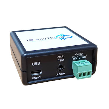
This device detects audio from your 3.5mm stereo socket and uses the audio as a means to control a relay output.
Simple to use, simple to install.
Simply plug in the USB to supply this converter with power.
Plug in your audio jack for the audio sound input.
When sound is detected from your audio jack, the relay will be activated.
Application
- Convert sound into a light indicator.
- Convert sound alert into another alarm tone.
- Use with PIC-124 Mute Switch to control sound/alarm.
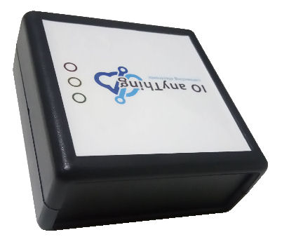
![Audio activated relay [PIC-125]](https://www.pic-control.com/product/pic-125-audio-activated-relay-switch-output/pic-125-audio-activated-relay-output1.jpg)
Features
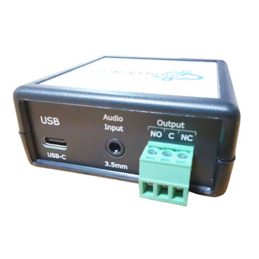
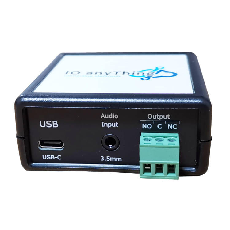
- Power through USB mini-B port (5V).
- Socket for a 3.5mm stereo audio jack.
- 3.81mm pluggable connector terminal for
- the relay output with NO (Normally-Open), NC (Normally-Close).
- Relay output rated at: 2A (up to 30Vdc) or 1A (125Vac).
- Set the relay output duration through adjustment POT inside the device.
- Configurable settings through USB virtual serial communication port.
- Green LED indicates power available.
- Yellow LED indicates sounds coming from the Left/Right audio channel.
- Red LED indicates when the relay output is activated.
- Size 67 x 67 x 24mm
Video Demonstration
The following is a video demonstration of this PIC-125 Audio Activated Output Relay.
This first green dot light indicates the device is operating with power coming from the USB connection.
The 2nd & 3rd yellow color indicator represent the left and right channel of your 3.5mm audio input jack plugged in. When there is audio present on the audio input, the indicator from the respective channel will get lighted up.
*** Tips: Adjust the output volume of your equipment’s audio output up to improve the detection. This helps you to adjust the sensitivity that you need.
The 4th red indicator represents the output relay activated. In this demonstration, the relay output is not connected. This output provides you with a normally open/close output so that you can interface to other external devices.
Before the audio is played, you will notice the red indicator is off. Once the music comes in, the yellow indicators get lighted up, and the red indicator (output) gets activated shortly.
In this video, the music playback is put to pause (demonstration purpose) before the next page of lyrics.
When the music is paused, there will be no audio input. You will see the yellow indicators immediately lights off. The red indicator remains activated for a duration of 1½sec before it is turned off. This output relay timing can be adjusted to suit your own application.
Shortly after, the music playback resume. The yellow indicators get lighted up again, shortly followed by the red indicator. The process repeats again for each page of lyrics to demonstrate to you how this PIC-125 Audio Activated Output Relay behaves.
The title of the music lyrics in this video is “I Have a Dream” from Mamma Mia The Movie.
Output
The output can be access via the 3 way pluggable terminal connector (in green). The output is activated upon audio is detected. If there is no audio detected after a period of time (adjustable), the relay will be deactivated.
When the output is activated, the Output port NO and C will be electrically connected (shorted). When the output is deactivated, the Output port NC and C will be electrically connected.
This electrical connection is simply like a mechanical switch connection. It does not have any voltage or current output. This connection can conduct up to 2A (30Vdc) or 1A (125Vac).
If your output device requires higher current or voltage than what the relay of this output can support, you can do so with an additional bigger relay connected in-between. Using this built-in relay to trigger a bigger relay that can power up your external electrical device.
Adjusting the Device Timing
Opening up the device enclosure, you will find 2x blue POT on the PCB board as shown in the photo below. This is for you to manually adjust the timing. (You can also adjust the value through the USB port via a Terminal software).
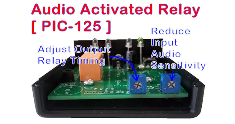
Adjust Output Relay Timing (POT1 on the left)
This POT1 controls the holding time of the output relay from 0.5 to 51.0 seconds.
Adjust the POT clockwise to increase the holding time. This means the relay can hold for a longer period of time after the audio is off.
If you need holding time longer than 51sec, this can be set via the USB connection through a Terminal software. You can set up to 999.9sec (about 16min 40sec) holding time.
Turn anti-clockwise fully to set the minimum holding time of 0.5sec.
Turn fully clockwise to set the holding time of 51sec.
Adjust Input Audio Sensitivity (POT2 on the right)
This POT2 controls the input audio sensitivity. It is disabled by default with a default sensitive of 9. You can set a value from 1 to 9. 9 being the most sensitive to any input audio. 1 being the least sensitive. You can consider setting this to less sensitive if there is noise mis-triggering the device.
As a default, 9 is set as admin mode. This means that you will not be able to adjust this setting via the adjustable POT. To adjust through the POT, you have to enable back the POT from the USB communication port.
Turn anti-clockwise fully to set the minimum count of 1.
Turn fully clockwise to set the maximum count of 9 (default-> most sensitive).
USB Configuration Settings
You can use a commonly available terminal program, example “Hyperterminal Program” to access to the configuration this PIC-125 Audio Activated Relay Switch Output.
Connect the USB cable and set up your virtual com port to the following,
- Baudrate 9600bps
- 8 data bits
- 1 stop bit
- No Parity bit
- No Hardware Flow-Control
Press ESC key (or send a byte 0x1B), to print out the following user menu.
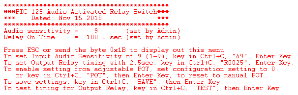
From this menu, you can see the current adjusted relay timing of 1000msec from your POT.
Press the <ESC> key on your keyboard to refresh the display as you adjust your timing.
Audio Sensitivity range from 0 to 9.
Relay On Time range from 0.5sec to 51sec, and can be set up to 999.9sec via this USB communication port
Besides adjusting through the POT, you can also send commands to fix the count or timing.
Command to set a new relay timing of 30.5sec will be for example “R0305“, and 180sec will be “R1800“.
Once this is set, use the command “SAVE” to save your new settings. This will ensure your new settings is preserved even after powering down the device.
This setting will have a higher priority than the adjustable POT on the PCB board. This means that the POT will be disabled. The settings done via the USB connection will be known as Admin. You should be able to see “(set by Admin)” on the displayed menu instead if the word “(set from POT)“.
To enable back your POT adjusts feature, execute the command to set the value to 0, or send the command “POT” to enable both the POT for manual adjustment.
Setting for Audio Sensitivity of 5 will be “A5“. You can set anything from 1 (less responsive to audio input) to 9 (most sensitive to audio input).
You can test the relay timing using the command “TEST“. This will help you check with the hold time is enough for your application.
Things that you can configure,
- Input audio sensitivity.
- Output relay holding time.
![Audio activated relay [PIC-125]](https://www.pic-control.com/product/pic-125-audio-activated-relay-switch-output/pic-125-audio-activated-relay-output2.jpg)
If you have question and need more information about this product, feel free to contact us. We are here to support you.
![Audio Activated Relay Switch Output [PIC-125]](https://www.pic-control.com/product/pic-125-audio-activated-relay-switch-output/audio-activated-relay-pic-125.jpg)
Customised Audio Activated Relay
This product can be custom made for your special application.
Contact PIC-CONTROL for customising your audio controlled relay.
Check out the other related products,